
《1. Introduction》
1. Introduction
Inkjet printing was one of the first technologies to be developed for additive manufacture. In 1992, Sachs et al. at MIT described a method for manufacturing ceramic casting cores and shells by inkjet printing a binder phase onto a ceramic powder bed [1]. The binder phase acts as an adhesive, collectively binding the ceramic powder where it is printed, and leaving loose unconsolidated powder elsewhere. Once a layer has been printed, the powder bed is lowered and new powder is applied. This new layer has a second binder pattern printed onto it. An object is printed by repeating this process of lowering, adding fresh powder, and binder printing. The final printed object can be removed from the unconsolidated powder prior to final sintering, if required. This methodology has proved to be very versatile, and has been developed with new materials beyond those in its initial application concept. Today, additive manufacture by inkjet printing has applications in biomaterials, functional ceramics, and other areas. It has led to a low-cost method for the rapid fabrication of models, as well as highly successful commercialization.
A few years later, Xiang et al. at Brunel University, UK, developed another inkjet printing method—direct inkjet printing—in which a ceramic object is printed by the ejection of drops of ceramic powder suspended in a liquid slurry [2]. These drops dry to form a ceramic green body. Thus, by means of appropriate overprinting, a 3D object is constructed layer by layer in a conventional additive manufacture process. Figure 1 shows an example of a small inkjet-printed and sintered ceramic object from Ainsley et al. [3]. Direct inkjet printing is a more versatile printing method than powder-bed printing, because it allows the deposition of a large number of materials in parallel, solely limited by the complexity of the printing platform. Note that printing four materials in parallel is already a standard requirement for full color graphics (red, yellow, blue, and black); hence, the development of multiple-material printing platforms is not a serious technical challenge. Once it is possible to deposit different materials, inkjet printing can be used to manufacture heterogeneous ceramic bodies and structures with graded composition [4].
《Fig. 1》

Fig.1 Example of a small ceramic object fabricated by an inkjet printing additive manufacture process. (Reproduced from Ref. [3] with permission from Springer Science+Business Media)
The versatility of additive manufacture with direct inkjet printing lies in the nature of the ink. Inks can be made that are precursors to many engineering materials, either in the form of particulate suspensions or as solutions. Of course, there are limitations to ink design. The first of these limitations is that the ink must undergo a transition to a solid after printing, and the printed solid may require further treatment to achieve the desired material composition and microstructure. The second limitation is that the ink must be printable; that is, it must satisfy a range of physical constraints to allow reliable and repeatable drop formation at the printing orifice of an inkjet printer.
This article will limit its scope to direct inkjet printing as a method for fabricating ceramic parts by additive manufacture; this distinguishes it from earlier reviews of inkjet printing for manufacture and ceramic fabrication [5¯8]. It considers the drop-generation mechanism and the constraints this mechanism imposes on ink properties. In addition, this article discusses interactions between printed drops and the formation of 3D objects. An important consideration is the mechanisms that lead to defect formation during these processes, and whether inks can be designed to reduce their incidence.
《2. Inkjet printing》
2. Inkjet printing
The 19th century physicist Lord Kelvin (William Thomson) was the first to consider the possibilities inherent in the controlled direction of liquid through electrostatic forces, and even had a patent granted on this concept [9]. However, it is not clear from Kelvin’s patent whether his device would have created discrete drops or a stream of liquid. In any case, this was an idea before its time, because there was no way to provide detailed instructions to steer the droplets, and thus the device was incapable of drawing patterns except on a single line, limiting its patterning to the simple dots and dashes of Morse code. It was almost 100 years before the next development in this field occurred in the 1950s, when Siemens used this technique to replace galvanometric chart recorders [10]. Major advances in both drop-generation and drop-placement technology then occurred, developing inkjet printing further and making it practical for computer graphics output. Advances in manufacturing technology reduced both the cost and size of these printers, so that today, inkjet printers are seen as a relatively cheap personal or desktop printing solution.
The main commercial applications for inkjet printing remain in graphics, product marking, coding, and dating, among other conventional printing operations. However, in recent years there has been considerable interest in, and use of, inkjet printing as a fabrication tool in a number of technological areas. These areas include displays [11], plastic electronics [12], ceramic component manufacture [13], and tissue engineering [14]. It is now clear that inkjet printing is on the verge of becoming a ubiquitous manufacturing tool.
《2.1. Methods of drop generation》
2.1. Methods of drop generation
There are currently three mechanisms that are used in the commercial droplet generators required for inkjet printing. These mechanisms can be conveniently classified as continuous inkjet printing (CIJ), drop-on-demand inkjet printing (DOD), and electrostatic inkjet printing (EIJ). Each of these methods has its own particular requirements for the physical properties of the ink and a characteristic drop size range. Of these methods, both CIJ and DOD have a background in text printing and marking applications, and have been in commercial use for over 40 years.
CIJ generates a stream of drops through the Rayleigh instability of a liquid column ejected through a small nozzle. The nozzle is held at a potential relative to ground that transfers a small charge onto each drop. Individual drops are steered by applying another potential to deflector plates (Figure 2). Drop diameters are normally>50 μm and are slightly larger than the diameter of the nozzle. CIJ printers produce a continuous stream of drops; unwanted drops (when no printing occurs) are deflected into a gutter, and are normally recycled in many graphics applications to prevent waste. Drop generation rate can be>50 kHz and drops are ejected at velocities>10 m.s−1. Although CIJ produces the greatest volume of ink per minute, it is limited in terms of placement accuracy. Its main application is in product marking and coding. However, there have been examples of using this method for the 3D printing of ceramics [15]. The main concern with this method is that the continuous fluid jetting leads to significant ink wastage and, if recirculation is used, the potential for ink contamination.
《Fig. 2》

Fig.2 Schematic illustration of the operating principles of a continuous inkjet printer (CIJ). (Reproduced with permission from Ref. [7])
DOD printers generate individual drops when required, and do not steer a drop in flight. Drop placement occurs by mechanical positioning of the drop generator or substrate. Drops form through the propagation of a pressure pulse in a reservoir behind the nozzle. This pressure pulse must overcome the surface tension forces that hold the liquid drops in place; the resulting ejected column of liquid is pinched off to form a drop by a combination of surface tension forces and the return flow of the liquid in the reservoir. The pressure pulse can be formed either by mechanical actuation (normally by a piezoelectric device) or by the formation and collapse of a vapor pocket in the ink through local heating (Figure 3). The vapor-pocket mechanism is chiefly used in low-throughput desktop printing devices, while piezoelectric actuation is more common in high-volume commercial and industrial applications. With DOD, drop volumes are in the range of 1 pL–1 nL, with corresponding diameters in the range of 10¯100 μm. Drops are ejected on demand at rates up to about 20 kHz. Drop-ejection mechanisms in DOD and CIJ printers have been comprehensively reviewed by Martin et al. [16].
《Fig. 3》
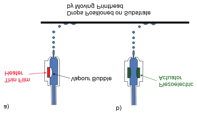
Fig.3 Schematic illustration of the operating principles of a drop-on-demand inkjet printer (DOD) with (a) thermal and (b) piezoelectric actuation. (Reproduced with permission from Ref.[7])
While CIJ and DOD printing are strongly controlled by surface tension forces and the conventional physics of fluid flow, EIJ printing works by a different principle. EIJ printing uses drops generated by the electrostatic repulsion experienced at a charged liquid surface. If a liquid surface is held at a sufficiently high potential and constrained mechanically, it will deform out of its plane and eventually form a highly curved apical surface—the Taylor cone. The field gradient close to the tip of the cone can become very large, resulting in the ejection of small liquid droplets in the electrospray process. EIJ printers operate by holding the surface potential of the liquid just below the spraying threshold, and using controlled pulses in the potential to eject individual drops [17]. This technique has only recently become commercially available, and will not be considered further in this article, although it may point toward a method of reliably producing smaller drops and introducing greater precision and resolution to drop-based manufacture.
By far the majority of published work on the use of inkjet technology for the additive manufacture of ceramics involves piezoelectric DOD [7]. The use of piezoelectric DOD rather than thermal DOD reflects the prevalence of piezoelectric actuation in commercial equipment. Thermal DOD introduces a constraint on ink properties, because a low boiling-point component is needed to ensure the easy formation of the vapor pocket. This article focuses on the use of piezoelectric DOD printing.
《2.2. Drop generation and ink design》
2.2. Drop generation and ink design
Inkjet printing has been studied intensively as a fabrication route for the manufacture of ceramic objects, using CIJ and both thermal and piezoelectric DOD technology [2–4,13,15,18[16]25]. There are a number of common requirements for a practical ceramic ink. Most importantly, the ink must be a ceramic suspension that is stable over a long period of time, without significant segregation or agglomeration of its constituent particles. It must have fluid physical and rheological properties that allow the formation of repeatable and regular drops at an appropriate drop-generation rate. Figure 4 shows an image of drops formed using a piezoelectric DOD printhead, with long fluid tails extending behind the ejected drops. These tails are characteristic of the DOD process and are also seen on drops formed using thermal inkjet. The surface tension acting on the extended tail will pull it into the spherical head while in flight; however, it is possible for the tail to break off during this retraction process, leading to satellite drops in the wake of the leading drop. Given that there is a relative motion of the printhead across the substrate during manufacturing with DOD printing, the satellite drop may impact in a different location from the parent drop, and hence compromise the resolution of a printed object. Thus, inks and printing conditions must be designed to eliminate the formation of satellite drops.
《Fig. 4》
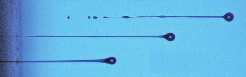
Fig.4 High-speed photographic image of drops generated from the printhead of an inkjet printer, showing the characteristic elongated tail and the formation of satellite drops. (Reproduced from Ref. [16] with permission from the Institute of Physics)
The ink must also have appropriate compatibility with an initial substrate. For 3D printing, the ink must have appropriate compatibility with previously deposited layers to allow the formation of stable and stationary sessile drops that interact with their neighbors to produce the desired pattern or structure. Finally, the ink must solidify, either by evaporation or phase change, to form a stable structure for subsequent post-processing.
The earliest significant work attempting to understand the mechanisms of drop generation was by Fromm [26], who identified the parameter Z=1 /Oh, where Oh is the Ohnesorge number defined as follows:
where ρ, η, and γ are the density, dynamic viscosity, and surface tension of the fluid, respectively; and a is a characteristic length—normally the diameter of the printing orifice; Z can also be formulated in terms of the Reynolds ( Re) and Weber ( We) numbers. Fromm proposed that Z>2 for stable drop generation. This analysis was further refined and experimentally investigated by Reis and Derby [27], in order to consider both the condition for drop ejection (minimum Z) and that for the onset of satellite drop formation (maximum Z), with the limits of 1< Z<10 for stable drop formation. This range of printability has been confirmed by experiments on particle-containing inks [6,8]. Jo et al. also found that increasing the fluid viscosity (decreasing Z) stabilizes the fluid tail and reduces the tendency for satellite drop formation [28]. Jang et al. reported on the printing of fluid mixtures of ethanol, water, and ethylene glycol to vary the parameter Z; they reported that fluids were printable within the limits 4< Z<14 [29], which are similar to the limits predicted by Reis and Derby.
Two further limiting conditions define a limiting regime for drop generation. Duineveld et al. proposed that there is a minimum velocity for drop ejection in order to overcome the surface tension at the exposed nozzle [30]. This minimum velocity can be expressed as a minimum Weber number for drop generation:

Finally, there is a maximum allowable drop velocity above which splashing occurs when a drop impacts a surface. An appropriate splashing threshold was proposed by Stow and Hadfield [31]:

where f( R) is a function of surface roughness; for flat, smooth surfaces, Bhola and Chandra found that f( R) ≈ 50 [32].
Equations and inequalities (1)–(3) define a region in a parameter space of Re and We that indicates the fluid and process properties compatible with DOD inkjet systems. Figure 5 shows this parameter space; note that the version of this figure in Ref. [7] is plotted incorrectly. The validity of this predicted regime of printability has been explored for a large range of fluid properties with particle-filled systems, and the parameter Z (Eq. (1)) appears to offer a useful guide for the selection of fluid properties. Note that these simple dimensional analysis methods assume the fluid to be Newtonian in behavior. There has been limited study of the fundamentals of drop formation in polymer solutions where non-Newtonian behavior is expected. Haskal et al. reported that the elongated tail characteristic of ejected drops was longer and more stable for solutions of poly( p-phenylene vinylene) [33]. They also found that the filament did not pinch off to form individual drops at molecular weights>300 000 in a range of solvents. Xu et al. reported that Newtonian fluids show elongated tails during DOD printing, and that these tails can destabilize into a train of satellite droplets that follow the main drop. They also reported that the action of small concentrations of polymers can stabilize the tail so that it retracts into the main drop during flight [34].
《Fig. 5》

Fig.5 Representation of a parameter space with axes of the Reynolds and Weber numbers, showing the region of fluid properties where inkjet drop formation is optimized. (Redrawn and corrected from Ref. [7] with permission from Annual Reviews of Materials Research)
Further work is therefore needed to extend the simple models of the printability of Newtonian fluids to the more complex non-Newtonian behavior of inks that are optimized for printing. A further consideration is the shape of the waveform that drives the piezoelectric actuator in DOD printing. Early work has demonstrated that acoustic resonances within the printhead are important in defining a waveform that repeatedly ejects a stable drop, especially as the drop generation rate reaches frequencies>1 kHz [35–37]. Jo et al. also found that the shape of the actuating pulse could influence the fluid properties at which satellite drop formation occurs [28].
《2.3. Drops in flight》
2.3. Drops in flight
The image of inkjet drops just after formation in Figure 4 shows the characteristic long fluid tail and possible satellite drop formation. These satellites may catch up and merge with the leading large drop in flight, prior to impact. In order to allow adequate time for tail retraction or for satellite drops to merge with the parent drop, in DOD printing it is normal to print with a stand-off of 1–3 mm between the printhead and the substrate. However, the stand-off cannot be too large, because it also affects drop-placement accuracy due to the influence of stray air currents on the drop in flight.
Duineveld et al. considered the drag of the surrounding atmosphere on printed drops using the following empirical modification of Stokes’ formula for the drag coefficient of a sphere, where CD is valid for the Reynolds number range (using the fluid properties of air) 2< Re<50, which covers the range of typical inkjet drop sizes and velocities [30]:

Using Eq. (4), they obtained the following relationship between the dimensionless velocity of the drop, u*, and the dimensionless distance travelled from the printhead, x*, with:
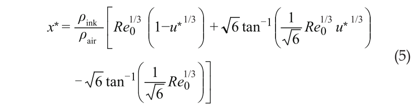
where x* = x/a with x representing the distance travelled by the drop and a representing the diameter of the printer orifice; u* = u/u0, where u is the velocity of the drop and u0 is the initial drop velocity; Re0 is the initial Reynolds number of the liquid drop as it leaves the printhead; and ρink and ρair are the density of the ink and air, respectively, at standard conditions. Eq. (5) is plotted in Figure 6 for the range of Re valid for Eq. (4) and using the density of water to represent an arbitrary ink. The line corresponding to Re ≈ 16 represents a 50 μm diameter drop of ink travelling at 5 m.s−1 in air, which indicates that the drop’s velocity is reduced to 0.9 of its initial velocity value after travelling x* = 33 (a distance of 1.65 mm for a 50 μm drop). However, a 10 μm diameter drop has Re ≈ 3 at the same initial velocity, and from Figure 6, it will travel a distance of x* ≈ 10, or approximately 200 μm before its velocity is reduced to u* = 0.9. At this drop size, the drop velocity will reduce to u* = 0.5 after travelling only 1 mm. Thus we can see that if we wish to improve the resolution of objects made by additive manufacture using inkjet deposition by reducing the size of the printed drop, we must decrease the distance between the drop generator and the substrate in order to eliminate the influence of drag. If the drop size<10 μm, the distance between the printer and the surface becomes too small to be practical for additive manufacture.
《Fig. 6》
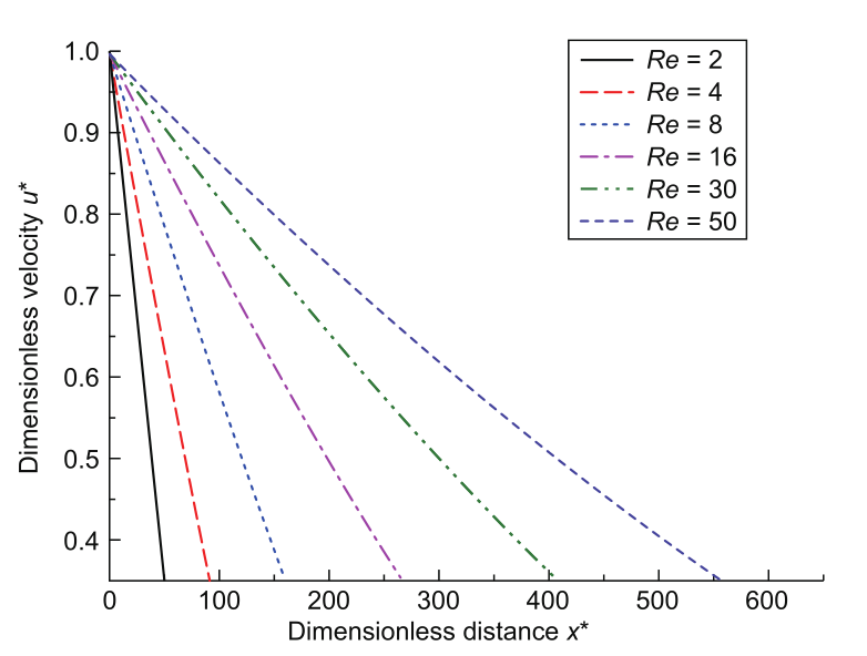
Fig.6 Illustration of how atmospheric drag reduces the velocity of a drop in flight as a function of distance travelled (normalized by drop diameter) for inkjet drops represented by the Reynolds number of typical drops.
《3. Building an object from drops》
3. Building an object from drops
For inkjet printing to fabricate 3D objects, there must be a transformation from a liquid to a solid. An isolated drop on a substrate is expected to form a stable sessile drop prior to solidification. Drops will typically have a volume in the range of 1¯100 pL, or in flight a diameter in the range of 10¯60 μm. These will form a sessile drop that can be accurately described by a spherical cap, because the Bond number is substantially below 1 and thus the drop shape is controlled purely by capillary forces. In order to form a solid object, adjacent drops must interact. Thus, there are two processes that must be considered: First, adjacent drops coalesce to form a continuous object; second, the object transforms from a liquid to a solid. Important questions exist for the first process, concerning morphological stability with capillary forces dominant. The second process, solidification, may occur by the evaporation of a solvent or by a phase change of the liquid; the phase change can occur by cooling through a solidification temperature, gelation induced by loss of solvent, or polymerization induced by an external agent such as temperature or radiation. Timescale plays an important role in these processes, because although some capillary-driven flow is necessary to form an object from adjacent drops, this flow will be controlled by the timescale over which the liquid remains on the surface before solidification.
《3.1. Drop impact》
3.1. Drop impact
During inkjet printing, a drop arrives at the surface at a speed of typically 1¯10 m.s−1 and its behavior on impact with a substrate depends on the initial velocity. Yarin reviewed the impact behavior of drops in the size range appropriate for inkjet printing, and found that the initial spreading of the drop is controlled by dynamic processes [38]. First, the drop spreads, converting kinetic energy into surface energy. With large drops and high drop velocities, a splashing instability may occur at this stage; however, under inkjet printing conditions, this is unlikely to occur. This dynamic spreading is followed by a surface-tension-driven retraction, and a process of oscillation that dissipates energy before the drop stabilizes to its equilibrium shape under capillary forces. The dynamic processes typically occur over timescales of μs, with capillary spreading requiring several ms to reach equilibrium. Assuming it forms a spherical cap, the equilibrium contact diameter of the drop, deqm, can be calculated using the following equation:
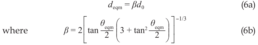
and d0 is the diameter of the drop in flight and θeqm is the equilibrium contact angle.
《3.2. Drop-drop interaction and printing lines》
3.2. Drop-drop interaction and printing lines
In order to fabricate an object from drops, the drops must interact to form higher-dimensional features. The design of droplet generators used in inkjet printers is such that drops can be more easily arranged to overlap in the direction of travel of the printhead relative to the substrate. Thus, the primary interaction between adjacent drops forms a linear feature. Hence the printing of lines is important, whether inkjet printing is being used to form linear features such as interconnects in a printed electronic circuit, or whether many overlapping lines are printed to build up a 3D object. The desired linear feature obtained from a series of overlapping drops will have a uniform height and width, with the resulting printed track having parallel sides.
There are a number of questions that must be answered regarding the stability of a line formed by overlapping liquid drops. First, let us consider a liquid line or bead. We might expect such a line to be inherently unstable; a driving force should exist to cause it to break up into a series of isolated sessile drops in a manner similar to the destabilization of a column of liquid via the Rayleigh instability. This problem was considered by Davis in the form of three limiting conditions for the contact angle and the contact line [39]: ① The contact angle is fixed and the contact line is free to move; ② the contact angle is a function of the moving contact line speed with a limiting value at zero line speed; and ③ the contact angle is free to change but the contact line is fixed. He found that for case ① and case ②, the liquid line undergoes a Rayleigh instability, but for case ③ the liquid line is stable when the contact angle<π/2. Davis’s predictions were validated in a subsequent experimental study by Schiaffino and Sonin [40].
Inkjet printing forms liquid beads through the overlap of adjacent spread drops. Clearly, if there is no overlap of drops, there is no mechanism for the formation of liquid beads. Two overlapping drops will tend to coalesce, and a train of overlapping drops will form a bead if the conditions of Davis’s case ③ are satisfied. Soltman and Subramanian carried out an experimental study of the formation of liquid beads from inkjet-printed drops [41]. At large values of drop spacing, where no overlap of the equilibrium sessile drops occurs, a train of discrete droplets is observed. At spacing slightly smaller than the diameter of the footprint, drop coalescence is observed, but the resulting liquid bead is “scalloped” and does not show parallel sides. At smaller deposited drop spacing, a stable liquid bead with smooth parallel sides is found, until finally the drop spacing is too small and a bulging instability is observed. The transition from a parallel stable track to one that shows irregular bulges was found to be a function of both drop spacing and the rate of drop deposition.
The transition from isolated drops to a stable linear feature was considered by Smith et al. [42] and modelled in more detail by Stringer and Derby [43,44]. At low values of Bond number, the liquid bead will have a section equivalent to the segment of a circle defined by the contact angle. The width of the bead, w, can be determined, assuming volume conservation, from the drop volume, drop spacing, p, and contact angle, using the following equation:

In Eq. (7), θ* is the static advancing contact angle rather than an equilibrium value.
In order for drops to overlap to form a stable liquid bead or track, their spacing must clearly be smaller than their equilibrium sessile drop diameter, that is, p<deqm or p<βd0 (see Eq. (6)). However, it is clear from Soltman and Subramanian’s work that the simple overlap of drops is not sufficient to ensure a parallel-sided track [41]. Stringer et al. proposed that this was because the receding contact angle of the printed drops was much lower than the equilibrium contact angle, and thus each printed drop was pinned [44]; in addition, if the drop spacing p was such that the predicted track had w<deqm, then the resulting track would be irregular. Thus a critical drop spacing exists, pmax, and a parallel-sided track can only form when p<pmax, with

The onset of the bulging instability observed at small values of drop spacing is the result of a more complex mechanism investigated by Duineveld [45], who explored the formation of lines from inkjet-printed liquid drops on a range of substrates with different contact angles. He found three regimes of behavior: ① When a liquid shows a constant contact angle (identical or very similar advancing and receding contact angles), the line is unstable, as predicted by Davis [39] and observed by Schiaffino and Sonin [40]; ② if there is significant hysteresis in the contact angle, stable tracks can be printed at low values of the receding contact angle; ③ however, even in this case it is not always possible to form a parallel liquid bead; instead, Duineveld observed bulges spaced regularly along the printed liquid bead under certain conditions of drop spacing and printing deposition rate. The onset of this bulging instability is a function of both drop spacing and the rate at which the line was printed (i.e., the traversing velocity of the inkjet printer relative to the substrate). Duineveld proposed that this instability is caused by competition between possible flow paths, which may occur when a newly deposited drop interacts with the leading edge of an existing liquid bead. At low deposition rates, a difference in Laplace pressure will drive liquid from the front of the deposit along the pre-existing bead. This transition in behavior occurs if the deposition flow rate (the number of drops arriving per second) exceeds the rate at which capillary spreading reduces drop curvature. This mechanism predicts that the instability occurs at small droplet spacing and low traverse velocities, consistent with the observations of Soltman and Subramanian [41].
Stringer and Derby adapted Duineveld’s model to obtain an analytical expression for the onset of the bulging instability [44], which can be expressed in terms of a dimensionless traverse velocity, UT*, which has a critical value that is a function of both the advancing contact angle, θadv, and a dimensionless drop spacing, g( p*,θadv). Thus the condition for a stable line is given by the equation

with

The function g( p*, θadv) is related to the inverse of the drop spacing and the contact angle, and is given explicitly in Ref. [44]. The two models expressed as Eqs. (8) and (9) can be combined, and are shown in Figure 7. The horizontal line at the top of Figure 7 represents the fact that for any given printing system, there is a maximum traversing velocity for the printhead; thus, there is a practical upper bound to the stability diagram. The function g( p*, θadv) increases with decreasing value of the dimensionless drop spacing, p*; hence, the vertical line to the left of the diagram defines the maximum drop spacing to produce a parallel-sided liquid bead or the minimum parallel-sided line width. The diagonal line defines the onset of the bulging instability at a critical minimum value of p*, which is a function of the printhead traversing velocity, and defines the maximum attainable line width. The physical value of the line width can be determined from any value of p* by using Eq. (7). The function g( p*, θadv) is such that the diagonal line is invariant with the contact angle, but the vertical line is a function of contact angle and moves to the left as θ decreases. Thus, Stringer and Derby’s model predicts that lower contact angle fluid/substrate combinations show a larger range of possible droplet spacing for stable contact lines [44].
《Fig. 7》
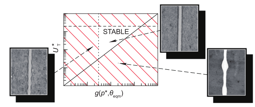
Fig.7 Illustration of the two instabilities that bound the region where stable parallel-sided printed lines are formed by droplet deposition. Axes represent a function of dimensionless drop spacing (modified by the contact angle) and a dimensionless drop traverse velocity. (Reproduced from Ref. [44] with permission from the American Chemical Society © 2009)
《3.3. Printing speed and build rate》
3.3. Printing speed and build rate
Inkjet printing is a drop-based manufacturing process, and the rate at which an object can be built depends on the rate at which drops can be delivered. Eq. (3) defines the maximum velocity at which drops can arrive at the surface before splashing occurs [30]. For these purposes, it is convenient to rewrite Eq. (3) in an equivalent form that includes the Z number, giving the following threshold for splashing:

Given that the domain of fluid properties for optimal inkjet printing is bounded approximately by 1< Z<10 (Figure 4), an upper bound, or splashing threshold, can be defined for inkjet printing with Re = 144 at Z = 10. Hence, the maximum impact velocity for inkjet printing, vmax, is inversely proportional to drop diameter, ad, with

The maximum frequency, f, at which drops arrive at the surface is determined by the spacing of drops in flight, df, with f = vmax/ df. From Figure 3, it is clear that for a 60 μm diameter drop, the tail extends over 900 μm; thus, drops are spaced by approximately 20 drop diameters to prevent interaction between drops in flight. The build rate for each drop generator is given by the drop frequency multiplied by the drop volume. Thus, the maximum volume deposition rate, V˙max, is
and the equivalent mass deposition rate is

Thus, given that the resolution of a built object depends on the droplet diameter, there is a clear trade-off between object resolution and maximum build rate. The build rates available for a single printing nozzle and a given drop size can be calculated if the density and dynamic viscosity of the ink are known. As an illustration, consider water and a ceramic ink as used by Seerden et al. [13] with respective densities of 1000 kg.m−3 and 1800 kg.m−3, and dynamic viscosities of 1 mPa·s and 15 mPa·s. For a 60 μm diameter drop, these values give maximum build rates of 2.5 × 10⁻¹⁰ m3.s−1 for water and 2.1 × 10⁻⁹ m3.s−1 for the ceramic ink per printing nozzle. A typical commercial inkjet printing head has up to 1000 addressable printing nozzles; thus, a maximum building rate of around 10−6 m3.s−1 is achievable per printing head, or approximately 1 cm3.s−1. These maximum building rates are certainly compatible with commercial production.
《3.4. Drop drying and the “coffee stain” defect》
3.4. Drop drying and the “coffee stain” defect
The transition from a series of printed drops to a solid object requires the initially liquid ink to transform into a solid. Although there are a number of methods that can be used to promote solidification, with ceramic materials the preferred route is normally the evaporation of a solvent. In order to fulfil the requirements of the dimensionless numbers that define printability, there is a practical limitation on fluid viscosity. The maximum value of fluid viscosity depends on the inkjet printhead design, but the highest viscosity liquids that have been used successfully for printing are typically in the region of 20¯30 mPa·s [3,13,22,23]. The viscosity of particles in suspension increases rapidly with suspension concentration, hence the maximum concentration of ceramic particles by volume in a printable ink is normally around 20%¯30%. Thus, the drop of ink deposited by a printer contains 70 vol.%¯80 vol.% of material that does not form a final solid. If this solvent solidifies without volume reduction, it must be removed by a subsequent processing step, which must be accommodated by substantial linear shrinkage of the printed object. Hence, if the solvent is removed by evaporation, the resulting ceramic powder body will contain>50% solid fraction, and consequent shape change after building will be reduced.
The drying of isolated drops and liquid beads may not result in a uniform dried deposit. Isolated drops of particles in suspension are often observed to dry leaving a characteristic ring deposit close to the initial contact line of the sessile drop. This inhomogeneous deposition is known as a “coffee ring” or “coffee stain.” Deegan et al. demonstrated that this deposition was the result of the contact line being pinned, preventing the evaporating drop from receding [46]. The material near the contact line dries more rapidly, because it contains a smaller column height of fluid than the centre of the drop. In addition, because the contact line is pinned, a flow of liquid occurs from the drop centre during the drying process. This radial outward flow carries solute and particles to the contact line where they deposit preferentially [46,47]. This “coffee stain” phenomenon can result in highly inhomogeneous deposition (Figure 8), which may adversely affect 3D printed ceramic objects [48].
《Fig. 8》

Fig.8 Inkjet-printed drops of a ZrO2 ink printed onto a glass surface heated to (a) 25°C, (b) 35°C, (c) 50°C, and (d) 100°C. All conditions show a pronounced “coffee ring”±after drying. (Reprinted from Ref. [48] with permission from the American Ceramic Society © 2011)
Controlling and eliminating the formation of a coffee stain is normally carried out by engineering the fluid to generate fluid flows that oppose the radial outward flow driven by contact line pinning. This engineering is normally achieved through the Marangoni effect, or fluid flow driven by gradients in surface tension. Indeed, Deegan et al. commented that small differences in temperature caused by evaporation cooling could set up surface tension gradients that would oppose the radial flow [47], and similar surface-tension gradients may occur if evaporation changes the composition of the liquid drop. The importance of Marangoni flows during droplet drying can be estimated using the Marangoni number, Ma:

where Δ γ is the difference in surface tension between the drop centre and edge; r is the radius of the sessile drop; η is the fluid dynamic viscosity; D is the diffusion coefficient (thermal for temperature-induced changes in surface tension and solute for concentration effects). It is generally believed that Marangoni flows are significant if Ma>100. Both de Gans et al. and Zhang et al. computed very large values of Ma (approximately 106 × Δγ) for inkjet-printed drops [49,50]. Based on these calculations, even very small differences in surface tension of around 10−4 J.m−2 should be sufficient to prevent coffee staining. Hu and Larson considered this situation further [51], and found that coffee stains were suppressed when clean organic solvents were used in drying experiments, and that Marangoni flow dominated the evaporation-driven flow. They suggested that in water-based inks, the Marangoni number is reduced ( Ma « 100) because of the influence of contaminants on the surface properties of water.
In most practical inks, coffee staining must be considered a real possibility. De Gans and Schubert exploited the concentration-gradient Marangoni effect through the use of solvent mixtures [49]. They selected two solvents of different vapor pressure and surface tension values. The high-vapor-pressure solvent evaporated preferentially at the drop edge, causing a local decrease in surface tension, and generating a surface tension gradient increasing towards the drop centre. Suitably selected solvent pairings generate greater surface-tension gradients than are available from temperature gradients. The use of solvent mixtures to suppress coffee staining has been successfully applied to ceramic suspensions by Zhang et al. [50].
《3.5. From lines to planes and additive manufacturing》
3.5. From lines to planes and additive manufacturing
There are few published articles on how 2D features are fabricated from overlapping printed lines, and little or no systematic study of the mechanisms of formation of 3D objects from sequentially printed layers. Mott et al. considered printing isolated drops and using interlacing to fill in the gaps and print a plane, rather than printing overlapping lines [19]. They considered that this process led to a high risk of poor ink penetration between printed and solidified drops and a large surface roughness for each layer. They stated that it is better for printing with an appropriate drop spacing to allow overlap before solidification; the interaction between adjacent liquid drops and the consequent influence of surface tension will tend to produce smooth surfaces and eliminate possible defects between solidified drops. This smooth merging of sequentially printed lines was observed by Di Biase et al. during a study of printing thermally reversible gel structures [52].
Tekin et al. investigated the printing of 2D liquid films fabricated from arrays of printed drops arranged so that they overlapped in the two Cartesian directions [53]. They found that if a film is printed in a single sequence such that the film remains liquid until all the drops are printed, the film retains its rectangular shape. However, there is a motion of solute to the edge of the film, showing that a coffee stain forms during the drying of mm-scale liquid films. On the other hand, if the drops are printed in a sequence where isolated drops begin to solidify before the spaces between them are filled by an interlacing pattern, this effect is eliminated. Kang et al. studied the printing of films using fluids with a large difference between advancing and receding contact angle [54], and found that these fluids gave more stable structures, following the conditions described by Davis that stabilize liquid lines [39]. Kang et al. also developed a numerical model of the printing process, and found the presence of a bulging instability similar to that modelled by Duineveld for liquid lines of zero receding contact angle [54]. Soltman et al. investigated this phenomenon further, and found that for fluids with only a small difference between advancing and receding contact angles, printed films with square features are not stable, and considerable rounding of the corners of a feature occurs [55]. They also found that printing a few isolated drops, in this case at the perimeter of the feature, dries and stabilizes the subsequently printed film by pinning the contact line. Thus, it is clear that the behavior of printed films has many features in common with that of printed lines. All these studies found that smaller dimension films appear to be less stable and more prone to rounding of corners. This rounding of fine features can be clearly seen in the work of Noguera et al. [23], where what was designed as an array of square pillars of lead zirconate titanate (PZT) is transformed by capillary forces to an almost circular cross-section after inkjet printing additive manufacture.
The final stage in the additive manufacture process is printing sequential layers on top of previously solidified inks. There are two major differences between the environment experienced by printed drops that are deposited on a flat substrate, and the environment experienced by drops that are deposited in the second and subsequent layers. The second layer is printed on a surface made of a dried powder, which will be considerably rougher than the original substrate and which is also porous, having lost the majority of the solvent through evaporation. The increased roughness of the surface will result in a reduced effective receding contact angle and more stable features when liquid films form. The presence of a porous surface will also influence the drying behavior of subsequent printed layers, and has been shown to alter the coffee stain behavior, making it more likely to occur [48,56].
《4. Direct printing of ceramic structures》
4. Direct printing of ceramic structures
At present, the main application of inkjet printing in the ceramics industry is in the application of decorations to flat ceramic tiles, rather than in additive manufacturing [57]. Inkjet printing is a digital printing technology and thus can be used to produce patterns without the need for masks and dies. The application of inkjet printing to ceramic decoration is a natural extension of its use in the conventional paper- and textile-based printing industry. However, the glazes and colors that have been developed for inkjet tile decoration using inkjet printing are likely to be very similar to those needed for ceramic additive manufacturing, at least in their physical properties. Thus the expertise originally developed for ink development in the tile printing sector will enable the development of suitable inks for ceramics additive manufacturing. In addition, because these inks are for the most part pigment particulate suspensions, there has been a need to develop printheads that are compatible with highly loaded ceramic suspensions, which will also benefit ceramics additive manufacturing.
Although it has been shown in this study that the theoretical maximum building rate for additive manufacturing of ceramics is about 1 cm3.s−1, it is likely that additive manufacturing will first be used to fabricate small ceramic objects. An important sector for ceramic objects<1 cm3 in volume is that of dental prostheses such as bridges and tooth crowns. These applications also require a precise design that is individual to each patient, for which additive manufacturing solutions are ideal. The rival technology is the CAD machining of ceramic blanks, and there are significant concerns that this method might introduce strength-limiting defects. Thus, there has been considerable interest in applying additive manufacturing to dental applications, as reviewed by van Noort [58]. Ebert et al. have demonstrated that components with high strength and toughness can be manufactured from dental ceramics, such as TZP zirconia, by direct inkjet printing [59]. However, the molar crown printed by Ebert et al. showed a characteristic stepped surface relief that occurs with all additive manufacturing methods, and it is not clear whether this may limit the method’s application in practice. As with all human interfacing prostheses, there will be a number of regulatory hurdles to be overcome before additive manufacturing methods are accepted for clinical use.
《5. Conclusions and proposed future work》
5. Conclusions and proposed future work
Ceramic ink development is now relatively mature, and a number of publications have demonstrated that it is possible to use direct inkjet printing to manufacture objects from a range of ceramics including Al2O3 (Figure 1) [3,13], PZT [22,23], and ZrO2 [48,59]. Further examples printed from other materials are readily found in the literature. There is now a reasonable level of understanding of the important physical and rheological requirements for successful ceramic ink development, with good data on the limiting conditions of fluid physical properties that are required for stable drop formation. There appears to be general agreement that the simple dimensionless number approach represented in Figure 5 provides a useful guide for the initial stages of ink formulation. However, all the experimental and theoretical work on which this model has been based has used very similar droplet generators or printheads that comprise of a single actuating chamber with a tubular piezoelectric actuator [26,27], and most experiments have been carried out using printers made by Solidscape (Merrimack, NH, USA) [6,13] or Microfab (Plano, TX, USA) [29]. Thus it is not clear whether Figure 5 provides a true representation of the properties of a universal ink or is specific to a particular geometry of droplet generator. In addition, although it is recognized that the addition of polymers to an ink influences the stability of the long tail on an ejected drop (Figure 4), there has been little research published that quantifies the influence of polymer type and molecular weight. Hence, despite encouraging developments, there is still substantial work to be carried out in order to understand the key features of ink formulation for DOD printers.
This article has highlighted some of our understanding of the mechanisms of drop spreading and coalescence that control the transition from drops of liquid ink to a solid ceramic object formed by additive manufacturing. A key concept in our understanding of how drops interact to allow stable features to be printed relies on the hysteresis between the advancing and receding contact lines as a drop impacts and spreads on the surface. Davis demonstrated that a low receding contact angle is necessary to allow a line of overlapping drops to form a stable linear liquid bead [39]. This was then shown by Stringer et al. to impose a lower limit on the narrowest line that can be formed by overlapping drops [44]. Stringer et al. also developed a model that can be used to define a maximum printable line width, and this is shown to be a function not just of drop spacing but also of the printing rate (Figure 7).
Additive manufacturing using inkjet printing builds an object by overlapping printed lines, because of the nature of nozzle spacing in a commercial inkjet printer. The interaction of adjacent printed lines to form 2D objects is much less well understood, and preliminary work has indicated that printed 2D structures are inherently less stable than printed lines [53¯55], and that capillary forces tend to prevent small-radius angled features from being accurately depicted. It is likely that this is a limitation to all droplet-based additive manufacturing methods, and that the spatial resolution/accuracy of a printed object is limited by the constituent drop diameter.
Thus, if higher resolution is required, it is necessary to reduce the drop dimension. However, there are two limiting factors that limit the practical smallest drop size. First, there is the relation between drop size and material build rate as defined by Eq. (12), which shows that the maximum build rate decreases with decreasing drop size (better spatial resolution). In addition, the drag-induced deceleration of a drop in flight becomes greater as the drop size decreases (Figure 6), and so the distance between the drop generator and the printed object becomes very small as the drop size<10 μm. These factors will probably limit the practical smallest drop size for DOD printing to the range 1¯10 μm.
Finally, we need a better understanding of the “coffee stain” mechanism and how it relates to surface roughness and/or porosity when overprinting. Coffee stains are also related to advancing and receding contact angles, because the drying perimeter of a sessile drop of a particle suspension tends to be pinned by the drying ring at the contact line, generating an effective zero receding contact angle. This line-pinning phenomenon generates the driving force for the outward radial flow that produces the coffee stain. It is generally believed that coffee staining can be eliminated by suitable engineering of the ink formulation in order to exploit Marangoni convection [49,50]. However, it should be noted that the mechanism by which coffee stains are eliminated is not perfectly understood, because simple estimates of the Marangoni driving force suggest that it is a much more potent force than is in fact the case, and that surface contamination of the ink may distort model predictions [51]. Thus, formulating a ceramic ink to eliminate coffee stains is potentially a greater challenge than the simple mechanism model suggests.
Finally, it can be seen that inkjet printing provides an attractive route for the additive manufacturing of ceramics. It is likely that initial commercial use of the method will be in a specialist niche application that requires individually designed small components, such as dental ceramics.


 京公网安备 11010502051620号


