

《1.Introduction》
1.Introduction
The rapid increase in carbon dioxide (CO2) emissions over the last decades is related to the development of industry and transportation. In recent years, there has been a technological effort toward CO2 capture in order to remove it from the atmosphere. However, the large amount of CO2 produced annually, which amounts to more than 32 GtCO2 [1], prevents a future in which CO2 is only sequestered. We need to make use of it. Lately, CO2 has also been reused as a carbon source. The US Department of Energy presented a diagram of possible uses for captured CO2 [2]. These include direct use in the food industry (i.e., carbonated beverages); use as an extractant, refrigerant, fire suppressant, or inerting agent; and use for enhanced fuel recovery and for the production of chemicals, polymers, and fuels. CO2 can be used as a raw material in the production of urea or polycarbonates, as well as in the production of bulk chemicals such as methanol or methane. A number of papers have shown various processes for the transformation of CO2 into different chemicals via hydrogenation [3]—into methane [4], methanol [5], or dimethyl ether (DME) [6]. In order to transform it into other chemicals, a reduction reaction of the CO2 is required—the very process that plants perform naturally. Today, biomass-based fuel production uses the CO2 fixed by plants in the form of hydrocarbons to produce bioethanol, biodiesel, and so forth [7]. Aside from food-linked raw materials, algae and lignocellulosic raw materials such as switch grass are useful for biomass-based fuel production. As an example, let us focus on diesel substitutes such as DME. DME can be produced directly from biomass-based syngas [8], or obtained using CO2 and renewable hydrogen (H2) [6]. For this comparison, it is paramount that the energy source be renewable. In this perspective work, both processes are compared in order to examine the performance of the technologies that reuse CO2—one being a natural process, and the other an engineered process to transform solar energy into power using photovoltaic (PV) panels or concentrated solar power (CSP) facilities.
For a systematic analysis of technologies and of the operation of processes, the mathematical optimization approach is a powerful tool. This analysis involves modeling all the units that form part of the process flowsheet using mass and energy balances, chemical and phase equilibria, experimental data, and rules of thumb. Next, a superstructure of alternatives is built, which includes the major technologies and network flows that allow the processing of a certain raw material or energy source into a product. The model is typi cally formulated as a mixed-integer nonlinear programming (MINLP) problem. To tackle this problem, numerical routines and/or decomposition algorithms are required [9]. Only after solving the problem can we compare different processes from various sources. Water and energy consumption optimizations are either done simultaneously or performed after the process design. Finally, a detailed economic evaluation is carried out for a more complete comparison of the operating data. The three alternatives are compared in terms of their use of natural resources, including land use and water and energy consumption, and in terms of an economic point of view. It is beyond the scope of this work to develop an integrated metric to compare the alternatives; rather, the aim here is only to describe and compare the results of the analysis and to suggest pros and cons toward the use of different renewable technologies for the production of the same product, DME.
The paper is organized as follows: Section 2 describes the technologies and presents their flowsheets. Section 3 shows the operating information regarding needs and consumptions, and discusses pros and cons of the alternatives. Finally, Section 4 contains some conclusions.
《2.Process description and design approach》
2.Process description and design approach
This section describes three alternative technologies for the production of DME. The first technology consists of the use of lignocellulosic biomass, which can be considered the natural product of CO2 capture using solar energy. The second and third technologies involve the production of power from solar energy using either PV panels or CSP facilities, and its further use to hydrogenate CO2 toward DME. The processes are modeled unit by unit, including all heat exchangers, reactors, columns, and so forth, based on first principles, thermodynamic and phase equilibria, rules of thumb, etcetera. A simplified profit is used as an objective function to optimize each process. The selection of the process and operating conditions corresponds to the solution of a mathematical MINLP problem of the following form [9]:

where the constraints h(x, y) and g(x, y) correspond to the models of the units. The model is solved to optimality in order to determine the operating conditions and the technologies involved in the final flowsheet.
Next, economic evaluations are performed, including investment and production costs. For the investment, the factorial method is used, which allows the estimation of the total investment as a function of the equipment costs. The equipment cost estimation is performed using parametric charts or correlations as a function of a characteristic variable such as a dimension, a mass, or an energy flow. Unit sizing may be needed to compute the equipment’s characteristic dimension. It can be carried out by means of short-cut designs of the unit, in order to estimate the heat exchanger area or the column diameter. The production costs include labor, maintenance, raw materials, utilities, administration, and other general expenses [10].
《2.1. Biomass-based dimethyl ether》
2.1. Biomass-based dimethyl ether
In nature, plants capture CO2 from the atmosphere and process it via photosynthesis in order to grow. This process takes some months before the biomass can be harvested for further use.
CO2 + 2H2O + photons → [CH2O] + O2 + H2O (I)
Once biomass such as Miscanthus or switchgrass is available, it is processed to obtain syngas and DME. A number of technologies are available to process this biomass into syngas. First, the biomass is gasified. Two technologies are considered. The first technology, direct gasification, uses a single unit that requires feeding with pure oxygen (O2) in order to avoid gas dilution, and that produces a raw syngas with a high CO2 content but a low hydrocarbon content. In the second technology, the gasifier and the combustor operate separately, allowing the use of air to burn the char, and producing a raw syngas with a higher hydrocarbon concentration. Next, two reforming modes can be used—partial oxidation or steam reforming—transforming the hydrocarbons into H2 and carbon monoxide (CO). Although steam reforming generates a larger amount of H2, it is endothermic. Partial oxidation is exothermic, but the product gas has a lower concentration of H2. Subsequent gas cleaning for solids and sour gases removal are implemented to purify the syngas. A composition adjustment stage may be needed so that the proper H2-to-CO ratio is fed to the reactor. DME is produced by following direct synthesis, in a novel one-step technology.

The unreacted gas can be either recycled or used within a Brayton cycle for the simultaneous production of DME and power. Fig. 1 provides the superstructure. To determine the optimal set of technologies for gasification, gas reforming, composition adjustment, and operating conditions to process biomass into DME, a mathematical programming approach is used. The structure is modeled using mass and energy balances, chemical and phase equilibria, rules of thumb, and experimental data, such as in the case of the gasifiers. Thus, the problem is formulated as a MINLP problem. The optimal process presented by Peral and Martín [8] involves indirect gasification followed by steam reforming and wet solids removal. DME production is favored over power for current electricity prices.
《Fig. 1》

Fig. 1. Superstructure of biomass-based dimethyl ether (DME) production. HBC: hydrocarbons.
《2.2. Solar-based dimethyl ether》
2.2. Solar-based dimethyl ether
In the artificial scenario, the CO2 captured by any industry can be reacted with H2 to produce DME. In order for this process to be renewable, the H2 must also be renewable. On the one hand, H2 can be produced from biomass [11]; however, this process does not make much sense, since it returns to the atmosphere the CO2 that was previously fixed in the form of biomass. Thus, this process only recovers the H2 from water that was used to build the hydrocarbons. On the other hand, solar energy can be used to split water. In order to compare this process with the biomass-based process, the use of PV panels or CSP facilities is considered to capture solar energy and transform it into power.
Fig. 2 shows the structure of a CSP facility. It consists of the heliostat field, the molten salt circuit, the steam circuit, and the cooling system. Molten salts are heated in a heat exchanger that receives solar energy, and are then stored in a tank. The flow of salts from the tank is regulated over the day. Part of the flow from the tank is used to produce high-pressure steam, while a fraction is used in the regenerative section of the steam Rankine cycle. A cooling tower is typically used to condense the exhaust of the turbine, although dry-cooling technologies are also available. The optimal operation of such a facility is formulated as a nonlinear programming (NLP) problem for the selection of the Rankine cycle flows, temperatures, and pressures, as well as the use of salts for steam generation or the cooling tower for reduced water consumption. The model of the process uses mass and energy balances, rules of thumb for the cooling tower operation, and, more importantly, detailed correlations for the enthalpy and entropy to estimate the power generated from the turbine [12].
《Fig. 2》

Fig. 2. Scheme of a concentrated solar power (CSP) facility. HX: heat exchanger; HP: high pressure; MP: medium pressure; LP: low pressure; CT: cooling tower.
Once power is produced from CSP facilities or PV panels, it can be used to split water. Electrolyzers break down water and generate two streams that consist mainly of O2 and H2, respectively. Both streams must be purified by removing water, and then compressed. However, in the case of the H2 stream, O2 traces must also be eliminated. A deoxo reactor is used, which consumes a small amount of H2 to produce water. Thus, the final dehydration step is placed after the deoxo reactor. Next, DME is synthesized and purified.

Fig. 3 provides a scheme of the process. The optimal process structure, the use or recycling of the unreacted gas, and the operating conditions are computed by formulating the process as an NLP problem and modeling the units involved, following the same procedure as in previous cases. The unconverted gas can be recycled or used to produce power. This process presents a number of challenges due to the variability of solar energy; however, it allows the energy to be stored in a useful form.
《Fig. 3》
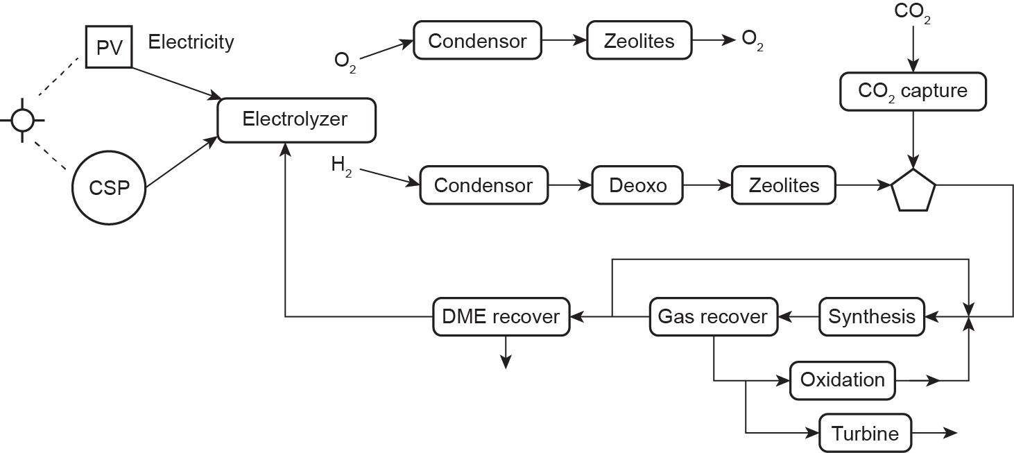
Fig. 3. Superstructure of solar-based DME production.
《3.Comparison of natural and artificial solar transformation technologies》
3.Comparison of natural and artificial solar transformation technologies
This comparison of technologies and paths toward the production of DME is carried out following a mathematical programming approach for the systematic analysis of alternatives and operating conditions. This kind of analysis requires an important modeling effort, including a comprehensive literature research, decomposition algorithms, and numerical procedures, in order to tackle the problem [9]. Based on a detailed process design and analysis [6,8], together with the work by L. Martín and M. Martín [12] for the CSP facilities, Table 1 shows a comparison of the three technologies described above, with the same production capacity. I have scaled up the technology described in Ref. [6] to match the biomass-based technology. The base case is that of a lignocellulosic DME facility using the typical biomass flowrate, which is used in most second-generation bioethanol plants. Scaling up the investment cost is a complex process. However, the structure of the cost-estimation procedure allows a simple scale-up procedure. The cost of the units was correlated as a function of a characteristic variable, such as the flowrate processed in gasifiers or the area of the heat exchangers [13]. This characteristic variable is directly related to the mass or energy flow involved in that particular unit. For example, area is a function of the heat load under fixed operating conditions. Furthermore, according to the code used for the detailed cost estimation, if a unit is bigger than the standard units, the limits appear in any cost-estimation tool, and the unit must be duplicated. Thus, by scaling the production capacity, it is easy to resize all the units and compute the number of units required per operation. The factorial method applies coefficients to estimate the total investment cost as a function of the units; therefore, it is easy to estimate the cost of the scaled-up or scaled-down facility. Determining the production cost is even easier, since most of the items are directly related to the production capacity, such as utilities consumption and raw materials. The other items are related to the investment, and can be scaled as described above.
《Table 1》
Table 1 Comparison between artificial and natural CO2 capture.
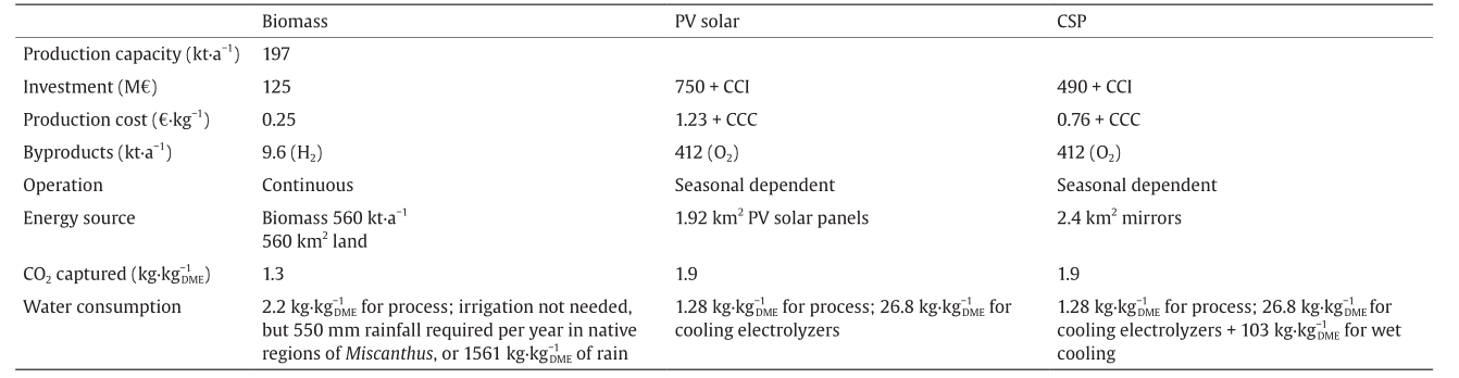
It is clear that biomass-based DME is cheaper by far. Not only is there a lower production cost, but also the investment required is only one sixth of that required for a PV solar-based facility and one third of the investment required when CSP is used to produce power. Thus, biomass has a competitive edge in this sense. However, there are other issues to be considered. Miscanthus has a yield of around 8–12 t·hm−2 [14]. Therefore, it requires an area devoted to biomass production of around 560 km2. Even though there is no need for irrigation if the plant is native to the region, rain must be plentiful for it to grow. Therefore, water consumption consists of two parts: the water required for the process, which is around 2.2  , and the water required to grow the biomass. If rainfall in the growing area is included, the second part of water consumption amounts to 1561 [15], which is certainly a large amount. The advantage of this process is that biomass can be stored for a period of time, allowing continuous operation of the facility.
In contrast, 1.92 km2 of land is required to produce the same amount of DME using solar PV panels (given their current cost and efficiency), while 2.4 km2 of heliostats is required for a CSP facility; thus, land use turns out to be an advantage for the artificial processes. However, production capacity varies with solar incidence, making the operation more complex. In terms of water consumption, the water involved in the artificial process is lower,1.28 , as a result of the lower operating temperature toward DME production. A second contribution to water consumption comes from utilities production and usage, resulting in an additional 26.8 for the use of PV panels and 103 if using wet cooling systems in the CSP facility. Although this water consumption is high, it is nowhere near the water that is needed to grow the biomass. Another important aspect that must be considered, which is not easy to quantify, is that of solar panel construction and its impact. Heliostats are mirrors, so their materials should be simpler than those of PV panels. Furthermore, CSP facilities have an advantage over PV panels in their capability to mitigate the effect of clouds and provide continuous daily operation due to the use of molten salts to store solar energy for 8 h or so.
In terms of CO2 capture efficiency for the production of DME via its hydrogenation, 1.9 kg of CO2 is used per kg of DME produced. If using switchgrass, it is estimated that 0.1799 kg of CO2 is fixed per kg of biomass [16]. Considering the amount of biomass used, 1.3 kg of CO2 is fixed per kg of DME produced. Artificial systems have an advantage in efficiency, but at a cost. However, while biomass can capture CO2 from a dilute atmosphere, the CO2 used as raw material when using PV solar or CSP must be concentrated.
So far, this analysis has not included the cost of CO2 capture technology because CO2 is typically captured somewhere else, such as at power plants. Using the information on carbon-capture yield and technology cost from David and Herzog [17], in order to capture the CO2 required for the operation of the facilities described in this work, the investment in carbon-capture equipment should be 10 M€, which does not represent a major additional burden to the investment costs presented in Table 1. Therefore, Table 1 shows the investment cost for the three processes. For those that use captured CO2, the investment cost of the facility includes the capture technologies with the term CCI. Similarly, the production cost shown on the table was computed without considering carbon capture. The increase in the production cost due to CO2 capture is 0.04 € per kg of DME. This contribution is added in Table 1 by the term carbon-capture cost (CCC).
However, another important issue related to the price of CO2, which is beyond the scope of this work, is that of CO2 transportation. Clearly, this cost is currently that of getting rid of a waste. If a tax is imposed on CO2 emission, the producer will be interested in an agreement to avoid paying that amount by having a user treat the waste. Thus, some agreement can be established between the producers and users of CO2. This issue is still at an early stage of discussion, so I prefer not to consider any of this cost in this study.
《4.Final remarks》
4.Final remarks
This work presents the use of a mathematical optimization approach for the optimal design of renewable-based processes and the further comparison of different technologies for the production of DME. The processes are modeled as MINLP problems based on first principles and experimental data, and are solved to optimality.
Thus far, biomass appears to be more efficient in capturing CO2, since both water consumption and economic parameters are in its favor. However, the area required for the plantation and the total amount of water consumed (if plant growth is also accounted for) indicate that the decision to use biomass is not a straightforward one. To be competitive, the production cost of PV panels must decrease to around 130  , which is approximately 10% of the current price, for a biomass price of 50 €·t−1; the cost of technology for a CSP facility must drop to one third of the current cost. The area required for biomass production is 560 km2. Thus, although their efficiency in capturing solar energy is quite reasonable, their prices cause PV and CSP technologies to lag behind biomass for the time being.


 京公网安备 11010502051620号


