
《1.Introduction》
1.Introduction
Without doubt, none of the arts is older than agriculture, but that of metals is no less ancient; in fact, they are at least equal and coeval, for no mortal man ever tilled a field without implements … If we remove metals from the service of man, all methods of protecting and sustaining health and more carefully preserving the course of life are done away with ….
Georgius Agricola (1556) †
† De re Metallica, published in Latin by Georgius Agricola (born George Bauer, in Saxony) in 1556, was the primary text for mining engineers, especially in Europe, for approximately two centuries. The first English translation was published in 1912 by Herbert Hoover (President of the United States, 1929–1933), a mining engineer, and his wife Lou Henry Hoover (https://en.wikipedia.org/wiki/De_re_metallica).
The extraction of minerals from the earth has been an essential element in the development of human society since the dawn of civilization‡. Considering the many remarkable technologies available today, it is easy to overlook the fact that almost all of these technologies are founded on, and would not exist without, minerals and the process of extracting them from the earth—that is, mining. Minerals also provide the mechanized equipment, fertilizers, and pesticides that are required to sustain the agricultural production levels necessary to feed the rising global population. Agricola’s words that are quoted above are as true today as they were over four centuries ago††.
‡ “… sub-Saharan Africa is the cradle of mankind from which Homo sapiens emerged some 100 000 to 200 000 years ago and there is abundant evidence in Swaziland of early Homo sapiens’ activity about 43 000 BC or 41 000 BC …” (http://www.sntc.org.sz/cultural/ironmine.html). The earliest known mines in Europe (at Spiennes, Belgium) date from 4300 BCE. Flint nodules were mined to a depth of 16 m in chalk (http://whc.unesco.org/en/list/1006). Excavation tools included picks made from deer antlers (https://en.wikipedia.org/wiki/Grime%27s_Graves [Tools]).
†† The recent YouTube video (2 min) titled “Is mining important?” reaffirms this fact (https://www.youtube.com/watch?v=JXoQQB0_3SM).
Can society be assured of an adequate supply of minerals in the future? Fig. 1 illustrates the importance of this question. For almost all of the 200 000 years or more that Homo sapiens has existed on this planet, earth’s population remained below 1 billion, and was distributed around the globe in small, predominantly agrarian communities.
《Fig. 1》
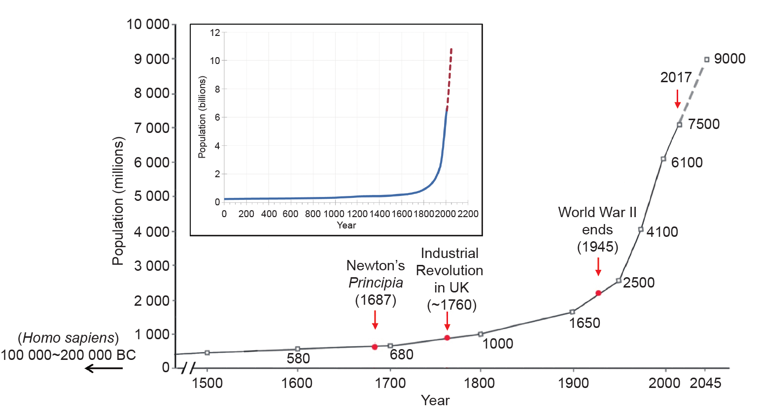
Fig. 1. World population over time and some significant “recent” dates.
The Industrial Revolution, which started in the UK in the second half of the 18th century, injected a new element, that of mechanization, which has dramatically transformed society in some parts of the world, but is still to arrive in others. Global population has increased more than seven-fold in the past 200 years and is projected to grow to 9 billion over the next 30 years (Fig. 1). Almost all of this increase will occur in the less-developed countries of Africa, Asia, and Latin America. The quality of life‡‡ of those living in many countries in these regions is much lower than for those living in developed regions of the world. Thanks to global communications, populations in these regions are much more aware of these disparities than was the case in the late 18th and early 19th centuries, and are anxious to move forward.
‡‡ As measured by gross domestic product per capita (https://en.wikipedia.org/wiki/List_of_countries_by_GDP_(PPP)_per_capita).
The demand for mineral resources tends to increase on the order of five times more rapidly than population growth [1], due to the desire to improve quality of life, especially in less-developed regions. Recycling and substitution can help reduce demand†††, but current rates are low. As noted in a National Research Council workshop in 2014, the question remains: “Can this population growth be achieved in a manner that is sustainable from an economic, social, and environmental perspective?” [2].
††† http://www.un.org/apps/news/story.asp?NewsID=38512#.WZ-mT1SGNGN
The provision of an adequate global supply of minerals is an essential element of this challenge. As noted by Bryant [3], this will require major innovation by the global mining industry, including greater emphasis on research and development. Exploration for new deposits benefits from satellite technology, but there is a parallel imperative to ensure that known deposits are developed to the fullest, in a manner that is consistent with safety, economics, and protection of the environment.
Although some surface mines now operate at depths in excess of 1 km, slope stability and other issues dictate a change to underground mining if the orebody continues in depth. For classical underground mining, that is, where miners extract ore via shafts, tunnels, and various mining methods, the depth to which the mine can be operated economically depends on the market value of the ore extracted. Thus, for a deposit with a gold content of 10 g·t−1 and a market price for gold of $40 g−1, the ore is worth $400 t−1. At present, the deepest mine in the world is the Tau Tona gold mine in South Africa, at a depth of 4 km. In contrast, coal is currently valued around $25 t−1, and most coal mines are shallower than 1 km.
Working conditions become increasingly hostile as depth increases. In the Witwatersrand gold mines of South Africa, special acclimatization programs were introduced in the mid-1960s, when the mines were around 2 km deep, to prepare miners for work underground [4]. The mines of the Kolar Gold Fields (KGF) in India experienced similar conditions [5]. Combined with declining ore values, these conditions resulted in closure of the KGF in 2001 at a depth of approximately 3 km.
Rockbursts have also been a severe problem, both in South Africa and in India. In 1994, the Leon Commission [6]† reported that “more than 69 000 mineworkers had lost their lives from 1900 to 1994 and a million had been injured, in South African mines. The report notes: “The major cause of fatalities and the single most important cause of reportable injuries has been rockfalls and rockbursts.” The International Symposium on Rockbursts and Seismicity in Mines (RaSiM) was introduced in Johannesburg in 1982, and remains an important forum for discussion of the rockburst problem [7].
† Also see http://www.klasslooch.com/leon_commission_of_inquiry.htm
Advances are being made in the development of remotely controlled mining equipment. Such equipment increases safety by reducing worker exposure to the heat/humidity and other dangers of the working stope, but it places increased emphasis on “ground control” for safety, to avoid damage or loss of mechanized equipment, and to avoid interruption of underground operations. Ground control R&D is generally not pursued by equipment suppliers.
The forces acting on the rock tend to increase with depth, so any examination of possible limits to the depth to which minerals can be mined economically must include a consideration of the ability to excavate the rock and maintain serviceable workings for as long as required. It is anticipated that ground control—including cost-effective mining and the maintenance of stable underground openings—will become the central issue in situations involving autonomous equipment. The following discussion focuses on the rock engineeringrelated issues of deep mining, recent developments in computer modeling of rock mass behavior that may allow more reliable prediction of rock mass response to mining, and limits to mining at depth.
《2.In situ rock》
2.In situ rock
Although rock, in the form of quarried blocks, was the primary material used over thousands of years to construct engineering marvels such as the pyramids, Roman bridges, Gothic cathedrals, and more, mining engineers must deal with rock as it is found in its natural environment. This is a very different material, to which the distinctive term “in situ” is applied. Civil engineers also encounter in situ rock when dealing with rock slopes and foundations, tunnels, and similar structures in or on rock.
Subject to successive epochs of tectonic and gravitational forces over hundreds of millions of years, or even a few billion years, in situ rock is a heterogeneous assembly of different materials that have been deformed, fractured and, in some cases, displaced by faulting, thus introducing a variety of discontinuities at various times and orientations in space, over a huge range of scales from microscopic grains to tectonic plates.
The tectonic and gravitational forces imposed on the rock are transmitted in part through the solid structure and in part by the fluid in the pore spaces within the rock. Some rocks will continue to deform and readjust slowly over millions of years, while other rock types in close proximity will remain more elastic and unchanging. The distribution of forces—and stresses—in the rock mass will vary correspondingly. Fig. 2 [8] shows two examples of non-uniform stress distribution on the scale of engineering operations. Similar variations can arise on all scales, whether larger or smaller than those shown in these illustrations. In a state of quasi-equilibrium, some regions are close to instability, and are referred to as being “critically stressed”; tectonic plate boundaries are an obvious example. Other regions may be far from this critical condition.
《Fig. 2》

Fig. 2. (a) Example of stress variations encountered while driving a tunnel through crystalline rock formations in Northern Sweden (courtesy of Professor Martna, Vattenfall AB, Stockholm, Sweden); (b) observed normal stress variations in the vicinity of an underground fault [8].
While driving a tunnel through crystalline rock formations in Northern Sweden (Fig. 2(a)), rockbursts occurred at a number of locations (shown in black along the tunnel) during excavation. Measurements at these locations indicated in situ stresses, “up to 10 times the calculated overburden stress σx”‡ (σx = ρgH, where H is the depth at the rockburst location). As seen from the two-dimensional (2D) section in Fig. 2(a), the tunnel is located within a geologically heterogeneous site. These formations, which are of varied geological ages and origins, have had many millions of years to respond to the changing applied loads. The weight of the overburden may be carried primarily through a three-dimensional (3D) “skeletal” structure with softer, more compliant formations being only lightly loaded.
‡ Personal communication from Professor Martna.
Fig. 2(b) shows the results of stress determinations made at several locations in the vicinity of a major fracture in the Underground Research Laboratory (URL), Pinawa, Canada [8]. It is seen that there is substantial variation in the stress component of acting normal to the plane of the fracture, with low normal stress in a region where the granite is altered (presumably reducing the rock modulus in this region), and high stress in regions with little alteration. There was no inflow of water when the URL shaft was sunk through the fault, whereas when a borehole was drilled into the low-stress region, several cubic meters of muddy material were ejected from the borehole and a surface-based farmer’s well in the vicinity was temporarily drained.
Earthquakes and volcanic eruptions serve as a constant reminder that the subsurface is also a “restless” environment. Rockbursts in deep mines and seismicity induced by hydraulic fracturing or by the filling of reservoirs†† are human-made reminders of this fact. A rock mass is a far more complex and uncertain material than any fabricated material used in other branches of engineering.
†† http://timesofindia.indiatimes.com/city/kolhapur/Koyna-earthquakes-triggered-by-reservoir-claim-seismologist/articleshow/50815347.cms
Little may be known in detail of geological conditions at the start of engineering activities, but these activities will certainly change the pre-existing equilibrium to some extent. In some situations, (e.g., sedimentary formations), the rock mass may be homogeneous over the full extent of the engineering project, although faulting may occur at discrete intervals within the region of extraction. Also, the response of the various rock formations to the rapid load redistributions associated with engineering operations may be quite different than the response of the same rock over geological time. Uncertainty and variability are characteristic features of rock engineering.
《3.Empiricism》
3.Empiricism
Mining and civil engineers throughout the history of civilization have learned to contend with the complexity of in situ rock, and have developed practical rules and guidelines, evolved through the classical trial-and-error empirical method of design. Prior to the publication of Newton’s Principia in 1687, essentially all engineering followed the empirical approach. This approach served well, as is evident from spectacular achievements such as the pyramids, Roman bridges and aqueducts, and the Gothic cathedrals of Mediaeval Europe. The Industrial Revolution was triggered by empirically derived innovation; the principles of Newtonian mechanics, although introduced some 70 years earlier† (Fig. 1), played essentially no role.
† https://en.wikipedia.org/wiki/Philosophi%C3%A6_Naturalis_Principia_Mathematica
Aided by the development of calculus in the second half of the 17th century, and the development of continuum mechanics by Cauchy (1821)‡, continuum elastic solutions to boundary value problems in mechanics [9–11] were developed and attracted the attention of engineers, leading to advances in several fields. Griffith’s [12] application of the Inglis solution [11] to explain the strength of brittle materials, for example, triggered the field of linear elastic fracture mechanics (LEFM), and led to today’s high-performance materials. World War II produced further dramatic advances in mechanics, and stimulated the development of computers.
‡ See https://en.wikipedia.org/wiki/Cours_d%27Analyse
Although the application of continuum elasticity (and plasticity) theory made some valuable early contributions to mining engineering [13–16] (see also discussion in Ref. [17]), and many more subsequent contributions as well, the overall complexity of rock masses has led to a continued emphasis on empirical rules in practice. An important principle of empirical rules is that they should not be applied beyond the bounds of established practice, from which experience the rules have been derived.
《4.Rock discontinuities》
4.Rock discontinuities
The collapse of the Malpasset Dam in France on 2 December 1959, followed by the Coalbrook coal mine disaster in South Africa on 21 January 1960, with loss of life in excess of 400 in each case, convinced Leopold Müller that rock engineering practice was venturing beyond understanding, and that the situation required international attention. Müller registered the International Society for Rock Mechanics (ISRM) in Salzburg, Austria in May 1962.
When explaining why the ISRM was needed, Müller drew specific attention to one particular characteristic of in situ rock, that is, pervasive, essentially planar, discontinuities: 3D systems of fractures produced at various orientations in the rock by tectonic and gravitational forces that had caused the rock mass to fracture at geological times in the past. As he noted in his Introductory Address at the First ISRM Congress (held in Lisbon in 1966): “… discontinuity and anisotropy are the most characteristic properties of the material rock … the properties of jointed media depend much more upon the fabrics bond of the unit rock block system than upon the rock.”
Müller’s comments, in fact, reopened a topic that had been debated vigorously during the early days of continuum mechanics. Can the mechanical behavior of real materials, all of which have a discrete microstructure, be represented correctly (or adequately) by the concept of a continuum? Filonenko-Borodich [18] provides an interesting insight into the early debate (see Section 1 in Supplementary Information) and observes that:
The fact that even an extremely small volume, presumably isolated from a body, contains a great number of molecules prompted investigators to appeal to the law of large numbers and to apply the method which was subsequently called statistical; this made it possible to bridge the gap between the continuous space of mathematical analysis and the solid body as a discrete medium.
It is important to note that the “discrete” elements of concern at that time were microscopic in scale. Elastic and plastic properties determined on small specimens of these materials in a classical laboratory can be applied to much larger volumes of the same material in engineering structures.
The discontinuities that were of concern to Müller and engineers dealing with in situ rock appear at a much larger scale, so the validity of the continuum assumption cannot be justified on the same grounds.
Müller’s comments and the founding of the ISRM stimulated considerable international activity in an attempt to take into account such “discrete” discontinuities [17]. The contributions of the inter-departmental Rock Mechanics group, established by Dr. Evert Hoek in 1966 at the Imperial College of Science and Technology (one of the colleges of the University of London then) in London, deserve special mention. The two pioneering books Rock Slope Engineering: Civil and Mining [19] and Underground Excavations in Rock [20] summarize some of the research accomplishments of this group.
The Hoek-Brown (H-B) criterion for estimating the strength of a rock mass containing joints and other geological features† was developed from this program, and is probably the most widely used international criterion today. It was introduced as part of Underground Excavations in Rock (op cit) in 1990, and has evolved considerably since then [21]. It is important to note that the H-B criterion is a continuum criterion, and assumes that the rock is isotropic. As noted by Hoek and Marinos [21]:
† The criterion is also applied for estimating the effect of confining pressure on intact rock (http://www.sciencedirect.com/science/article/pii/S1674775514000559).
A fundamental assumption of the Hoek-Brown criterion is that the rock mass to which it is being applied is homogeneous and isotropic. It should not be applied to the analysis of structurally controlled failures in cases such as hard rock masses where the discontinuity spacing is similar to the size of the tunnel or slope being analyzed and where the failure processes are clearly anisotropic.
The H-B criterion is also designed to be a practical criterion, for use by the field engineer: “It was recognized very early in the development of the criterion that it would have no practical value unless the parameters could be estimated from simple geological observations in the field” [21].
The contributions of two graduates of the Rock Mechanics group, Dr. Nick Barton and Dr. Peter Cundall, are particularly noteworthy in the context of this paper. Responding to Müller’s identification of discontinuities and anisotropy as fundamental characteristics of a rock mass, both Barton and Cundall have dedicated their professional careers—over 45 years so far—to trying to assess the role of 3D systems of discontinuities in the mechanical response of a rock mass to changes in applied loads.
Barton et al. [22] saw a need to identify practical rules to assist field engineers to take appropriate account of jointed rock. They introduced the empirical “Q system” [22] in 1974, and have continued to refine this system based on extensive observations of rock engineering in a variety of applications‡. Barton’s 2011 Müller Lecture [23] provides an excellent review of developments of the Q system over this period.
‡ A concise explanation of the Q system is provided on the website https://en.wikipedia.org/wiki/Q-system_(geotechnical_engineering).
Cundall [24] pursued the development of a computer model to represent the jointed rock mass as an assembly of blocks developed by through-going planar discontinuities, which interacted across the block interfaces. His paper [24] introduced the distinct element method (DEM) to rock mechanics in 1971. The method has been developed continuously over the subsequent four decades, and is now widely applied in rock mechanics.
《5.Distinct element method》
5.Distinct element method
The principle of the DEM is illustrated in Fig. 3. This method is based simply on the application of Newton’s second law of motion, F = ma, and on an assumed constitutive response (force–displacement relationship)†† at interfaces between elements of the system.
†† This relationship must be assumed, since field-scale data are generally not available. This is part of the uncertainty discussed earlier in this article. Development of massive parallelization techniques in computing allows such assumptions to be varied, and analyses repeated, to assess the sensitivity of the analyses to this assumption and to other uncertainties discussed in this paper.
《Fig. 3》
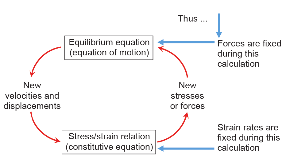
Fig. 3. The explicit finite difference method: the calculation cycle.
Any change in force acting on a body propagates through the system at the speed of sound. The dynamic response is represented numerically in the DEM using a time-stepping algorithm in which it is assumed that the velocities and accelerations are constant within each time step. To satisfy this assumption, the time step must be very small; to follow the deformation process requires a large number of time steps.
The DEM is thus computationally intensive, but it has the advantage that the deformation process can be followed in detail to final equilibrium—which may not be reached until complete collapse. By recording changes over very small time intervals, it also models the dynamic response of the system (which can be compared with the dynamic response observed in field microseismic systems). In addition, the forces and deformations at each time step are observed; from these, it is a simple procedure to develop a “movie” of the progression of the entire deformation process. This is a powerful way to communicate the model predictions to colleagues who may not be familiar with computational mechanics but who can recognize differences between computer predictions and field observations. Such interaction is an essential component of the iterative design process†.
† Some additional discussion of the DEM can be found at http://www.itascacg.com/software/pfc/distinct-element-method.
It should also be noted that 2D analyses of jointed systems can often lead to erroneous interpretation of the actual behavior of the 3D system [25–27]. Again, 3D analysis adds to the computational demand of the computer analysis. Inclusion of other factors, such as pressurized fluid flow, introduces yet another dimension.
Recent developments in massively parallelized and cloud computing dramatically increase the speed of computation for DEM problems, such that the method becomes more readily applicable to rock engineering and can take into account factors that may have a critical influence on both the predicted and actual behavior of the rock system.
《6.Synthetic rock mass》
6.Synthetic rock mass
The introduction of the synthetic rock mass (SRM) in 2007 [28], based on the DEM, was a major advance toward the consideration of a rock mass as a 3D (anisotropic) discontinuum (also see Refs. [25,26]). This advance comes more than four decades after Müller identified such discontinuities as central characteristics of a rock mass that can have a major influence in rock engineering.
The elements of the SRM are illustrated in Fig. 4 [28]. The deformability and strength of the intact rock, as determined from laboratory tests on cores, are represented in a bonded particle model (BPM) [29]—the yellow cylinder in Fig. 4. It is assumed that these BPM properties apply to the larger rock mass, exclusive of major discontinuities. A network of large-scale discontinuities is shown in the upper right block in Fig. 4; these are determined from field observations, and are referred to as the discrete fracture network (DFN). The DFN is superimposed on the intact rock block to form the SRM (center block in Fig. 4). The current status of DFN determinations and applications is discussed by La Pointe in Ref. [30]‡.
‡ See also ARMA Newsletter at http://armarocks.org/documents/newletters_r2/2017_issue_20_winter_.pdf
《Fig. 4》

Fig. 4. An illustration of synthetic rock mass [28].
The SRM is used to characterize the rock mass, which is subject to in situ stresses and so forth, and into which tunnels, mine workings, and more are developed and simulated in the computer analysis [31,32].
Fractures that are observed in a rock mass are of finite length. Although they can be defined into fracture sets with specific orientations, individual fractures may deviate somewhat from the mean orientation and mean length of a specific set. Also, although fractures are often assumed to be elliptical, this is typically not the case in reality.
Some of the uncertainties associated with models in rock mechanics can be illustrated by a discussion of the rectangular box in the lower right of Fig. 4. A main effect of the DFN is to concentrate the in situ stresses onto the region of intact rock between the tips of adjacent fractures. Due to differences in orientation and length between individual fractures, the overlap region may differ across the block. In one case, the overlap may be as shown in the box in Fig. 4—that is, with the lower fracture overlapping to the left of the upper fracture. It may also be the reverse—that is, with the lower fracture overlapping to the right of the upper fracture. Fig. 5 shows the result of a simple 2D analysis of the two situations, in which the uniaxial strength of a rock containing two fractures, with overlaps reversed, has been determined. It is found that the strength is 36% (7.6 MPa/5.6 MPa) higher in one case than in the other.
《Fig. 5》

Fig. 5. Crack development in rock bridges in fractured rock.
In Case 1 (strength 7.6 MPa), shearing will tend to develop tension (close to the tip) on the upper side of the upper fracture and similarly on the lower side of the lower fracture; that is, microcracking (the blue regions) tends to develop away from the overlap region. In Case 2 (strength 5.6 MPa), the situation is reversed; that is, tension develops on the lower side of the upper fracture and upper side of the lower fracture, into the overlap region. Case 1 requires a higher applied compressive load before interaction and failure occurs. (The situations shown in Fig. 5 are extracts from a movie showing the extent of cracking slightly before the crack regions coalesced and failure of the sample occurred.)
As noted earlier, DFNs are not precisely defined, and the extent of overlap will vary. There will be friction between the fracture surfaces. The 3D fracture network will be within a rock mass that is subject to a non-uniform stress field that may, for example, be in the vicinity of an underground roadway and/or be in a larger-scale region that is adjacent to a sizable cave. It is seen that the region of intact rock between the tips of fractures plays a crucial role in determining the strength of a fractured rock mass.
The discussion of Fig. 5 also underlines the following comment by Hoek and Marinos [21]:
One of the greatest sources of error in applying the HoekBrown criterion is a misunderstanding of the contribution of the intact rock strength σci, the role of which is almost equivalent to GSI [Geological Strength Index] in the evaluation of the rock mass properties. It is very common to see geologists confusing the intact strength with the rock mass strength and this results in significant under-estimates of the final rock mass strength.
In the case of a mining operation, in particular, the rock mass can undergo a succession of loading changes as the mining operation develops. As illustrated in Refs. [31,32], a rock mass containing discontinuities can exhibit behavior that would not be anticipated from, or exhibited by, a continuum analysis.
It is often the case that there is little or no information available on the fracture network when planning a mining operation. In such cases, it is preferable to assume a DFN rather than use an equivalent continuum, since the latter will not exhibit the same response to the load changes.
《7.Numerical modeling and rock engineering》
7.Numerical modeling and rock engineering
Starfield and Cundall [33] consider numerical models to be a valuable tool in rock engineering but emphasize that these models must be applied differently in this field than in most other engineering disciplines. Following Holling [34], they classify problems into four distinct types, as shown in Fig. 6 [33,34]: first, by the quality and/or quantity of available data; and second, by the level of understanding of the problem to be solved.
《Fig. 6》
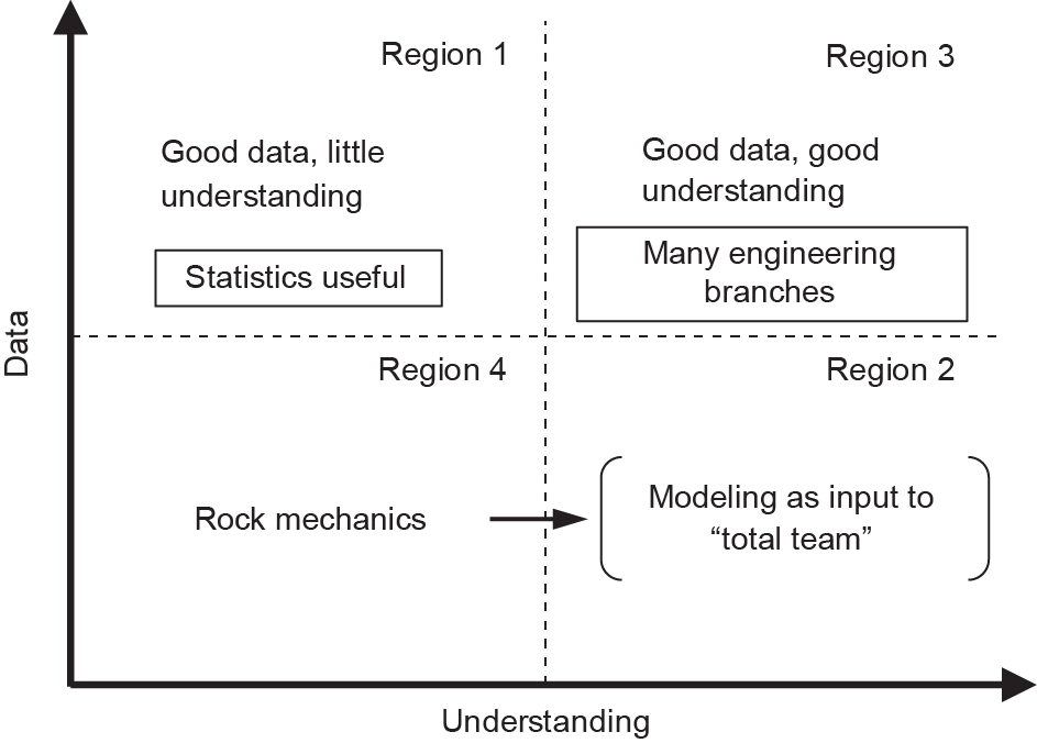
Fig. 6. Classification of modeling problems. (Adapted from Refs. [33,34])
Starfield and Cundall’s notes include the following comments, annotated here in square brackets:
In Region 1, there are good data, but little understanding— statistics is the appropriate modeling tool.
In Region 3, one has both the data and the understanding— this is where models can be built, validated, and used with conviction. [Region 3 is the region appropriate to modeling and design problems in many branches of engineering.]
Regions 2 and 4 relate to problems that are data-limited in the sense that the relevant data are unavailable or cannot be obtained easily… Problems in rock mechanics [and in rock engineering] usually fall in the data-limited category; one seldom knows enough about a rock mass to model it unambiguously.
They then add:
Rock mechanics models should never be run only once; it is in the sensitivity of the results to changes in parameters and assumptions that the model is most informing.
The model becomes a laboratory for those who built it.
A good conceptual model can lead to savings in time and money on field tests that are better designed.
The advances in computing power described earlier in this article underline the latter three points. It is now possible to run models many times over, performing sensitivity analyses such as by changing assumed values in a systematic fashion so as to identify key parameters and uncertainties.
It is also possible to examine the empirical procedures now used in rock engineering (e.g., Barton’s Q system) to establish the extent to which they are soundly based in mechanics or can be modified to improve their general validity. In this way, their use can perhaps be extended with greater confidence to predict behavior in untested situations.
《8.The rock engineering laboratory》
8.The rock engineering laboratory
Laboratory experiments have played a central role in the development of continuum mechanics. Hooke’s classic experiments demonstrating the linear relationship between the applied load and extension of a spring provided the basis for the linear theory of elasticity [35]. A glance through Nadai’s Theory of Flow and Fracture of Solids [36] provides numerous examples of how laboratory tests stimulated developments in the theory of plasticity.
Although the classical bench-scale laboratory has a valuable role in some aspects of rock engineering, the inability to include the large-scale elements of field problems in a classical laboratory test has been a significant constraint in rock engineering.
The computational developments described above now provide mining engineers (and others involved in rock engineering) with one element of a two-part laboratory: computer modeling. Linked closely with the other element—onsite observation and close interaction with the field engineer—3D discontinuum modeling of a rock mass opens important opportunities for mining. These opportunities are especially relevant to the question of establishing limits to the depth to which the extraction of minerals can be economically pursued.
The importance of the second element—critical assessment by experienced individuals—is captured in former US President Obama’s observation that “… the most powerful computer in the world isn’t nearly as intuitive as the one we’re born with.”† Careful development of this new, two-part “laboratory” can help move rock engineering problems progressively from Region 4 toward Region 2 in Fig. 6.
† Comment by President Obama on 2 April 2013 in Brain Initiative (https://obamawhitehouse.archives.gov/the-press-office/2013/04/02/remarks-president-brain-initiative-and-american-innovation, para. 8, last sentence).
Toward this goal, Sharrock (see Section 2 in Supplementary Information) has proposed an interesting variation of the back analysis procedure, used mainly in civil engineering by Sakurai [37], to compare the actual deformation of the rock around an excavation with that predicted in the original design analysis.
《9.Rock fragmentation and rapid excavation》
9.Rock fragmentation and rapid excavation
A major cost of mining, especially as operations go underground and deeper, is associated with the time required to develop the infrastructure of shafts, drifts, and so forth prior to the start of mineral production, and with the cost of rock fragmentation in general.
The following discussion illustrates the application of the DEM modeling procedure to dynamic problems of rock drilling and blasting and the reduction of the rock mass to small fragments.
At present, considerable effort is being made, as part of the development of mechanical excavators and autonomous mining machinery, to increase the effectiveness of rock fragmentation systems. Full-face tunnel-boring machines (TBMs) are popular for the driving of tunnels, and undercutting machines are finding application for ore extraction [38].
Although there is certainly room for innovation, fragmentation and the size reduction of rock are governed by fundamental relationships between the size of fragmented particles and the energy required to achieve the final size. Lynch and Rowland [39] provide a valuable discussion of comminution theories [40–43]. All of these relationships indicate that the energy required to reach a final size product is inversely proportional to the final fragment size. This is also predicted from Griffith’s analysis [12]. Fig. 7 [44] shows essentially the same relationship for a wide variety of fragmentation systems. (Nuclear explosions in rock are, overall, less efficient with respect to fragmentation than other systems, since much of the explosive energy is consumed in melting rock in the immediate vicinity of the explosive [45], and a wide range of fragments are produced.)
《Fig. 7》

Fig. 7. Specific energy (energy/unit volume of rock) as a function of nominal fragment size for various rock-breaking methods in quartzite. (Modified from Ref. [44])
This relationship (Fig. 7) notwithstanding, it is recognized that not all energy sources are equal with respect to fragmenting rock. Explosives are considerably more effective than crushing and grinding systems, and arguments are made that a greater use of explosives to blast rock to finer sizes prior to crushing and grinding has considerable economic merit: “Chemical energy is about 25 times more effective than mechanical energy for breaking rock, even though current explosives are still only 30% to 60% of their theoretical potential effectiveness for breaking and moving rock” [46].
TBMs have improved considerably since the introduction of the Robbins TBM at the Oahe Dam in 1952 [47]. Roller cutter life, bearings, and so forth have all reached a high stage of development and reliability. The cutting mechanism and fragment sizes produced remain unchanged and overall advance rates seem unlikely to increase substantially.
This suggests that it may be timely to examine opportunities for advancing the classical drilling-and-blasting procedure by the application of “smart” drilling-and-blasting systems‡. As noted in Ref. [38], the advance per blast in the typical drilling-and-blasting cycle is approximately equal to the tunnel diameter††. This was dictated by the need to design the blast to allow the rock fragments to be displaced toward the “free surface”—that is, the face of the tunnel. The use of a “burn cut,” in which a central cavity is developed, usually by intense blasting immediately ahead of the main blast round, helps to provide a free surface along the tunnel axis [38] and an open volume to accommodate the “bulking” of the rock fragments. The initial aim of the burn cut was to allow all of the holes to be drilled essentially parallel to the tunnel axis, but the burden (advance/blast) remained approximately equal to the tunnel diameter [38], as shown in Fig. 7. Chitombo and Trueman [48] carried out several “long-hole” burncut field trials in which they used a burden of twice the tunnel diameter, with no adverse effects. Apparently, no drilling equipment was available to try longer burdens.
‡ Nuclear explosions result in a wide range of fragment sizes, from solidified, initially molten rock, to very large fragments remote from the explosion. (See Ref. [42]Overview Fig. 1.9, Fig. 1.10, and para. 2.)
†† At a distance of one diameter ahead of the tunnel face, the state of stress in the rock is essentially unaffected by the presence of the tunnel face.
Fig. 8 illustrates a hypothetical drilling-and-blasting system in which a central hole is drilled along the axis of the tunnel, and a drilling round of parallel holes is arranged around the central hole in the classical manner†. Parallelism of the holes in the drilling round is controlled electronically from a series of guide holes drilled outside the periphery of the final profile, or from a control installed in the central hole. It is proposed to conduct a series of numerical tests to assess the feasibility of drilling the holes to a depth of several tunnel diameters in order to establish the sensitivity of the fragmentation to the parallelism of the hole, the possibility of controlling the latter from sensors in the pre-drilled central hole, and so forth.
† A stimulus for the notion of “smart drilling,” as discussed here, was the National Academies Report, Drilling and Excavation Technologies for the Future (1994), which can be found at https://www.nap.edu/catalog/2349/drilling-and-excavation-technologies-for-the-future: “Rapid innovation in microelectronics and other fields of computer science and miniaturization technology holds the prospect for greater improvements—even revolutionary breakthroughs—in these systems. The development of smart drilling systems has the potential to revolutionize drilling.” The remarkable developments in directional drilling for petroleum production (since this 1994 report) indicate the possibilities.
《Fig. 8》

Fig. 8. Long-hole “smart” drilling-and-blasting system (schematic only).
Since the drilling jumbo must occupy a somewhat larger cross-section than the final tunnel profile, it will be necessary to excavate a “launch gallery” to accommodate the extended jumbo at the start of each drilling cycle [38]. (This could be readily accomplished with a single cutter disc similar to that used on the Wirth undercutting machine [38], cutting parallel to the periphery of the excavation.)
The availability of a modified version of the code used by Furtney et al. [49] based on the BPM [29] and emphasizing the dynamic modeling capabilities of the DEM, plus the rapid processing techniques now becoming available, allows the investigation via computer simulation of various issues associated with this concept. Is it, in principle, possible to increase the advance/round to several tunnel diameters or more? What is the optimum way to develop the bulking volume: a single central hole, or several somewhat smaller holes distributed across the tunnel cross-section? Are there opportunities to limit the ground vibrations transmitted beyond the tunnel periphery (e.g., by adapting the “pre-split” technique)? Such computer studies could also help to inform possibilities for the explosive “pre-conditioning” of a rock mass in block caving. Indeed, the ability to examine multiple cases rapidly and inexpensively on the computer should allow us to assess the feasibility of a variety of possible innovations in mining—and, from these cases, to more intelligently plan field trials.
The long-hole drilling-and-blasting discussion above is one illustration of how mechanics-based “computer experiments” can now be used to assess the practicality of various designs, before committing to much more costly field tests. This is especially the case when contemplating the possibilities for excavation on the moon and on other planets.
As illustrated by Fig. 9 [29,50], the DEM modeling procedure can also be used to analyze rock fragmentation at the particle level, which is the central concern in the design of effective rock excavation systems‡.
‡ Study of the rock-cutting process led Detournay et al. (see http://www.sciencedirect.com/science/article/pii/S0013795212002244?via%3Dihub) to demonstrate that the compressive strength (and Mohr Coulomb failure envelope) of a rock can be determined by the use of a non-destructive “scratch” test. (A system is now available commercially: http://www.epslog.com/website/article.php?action=display&catId=2.)
《Fig. 9》
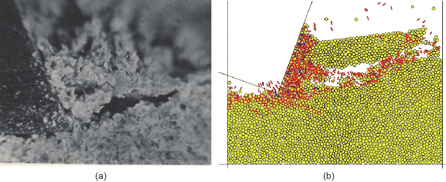
Fig. 9. Chip formation in rock cutting. (a) Physical observation [50]; (b) computer modeling [29].
《10.Discussion》
10.Discussion
The discussion above attempted to illustrate that recent and continuing developments in high-speed computation open a new phase in rock engineering. Although they are important in all subsurface engineering applications, these developments are especially significant in deep mining, where ground pressure conditions are likely to be severe, and where experience is limited.
Studies to date using the SRM indicate rock mass behavior that would not be anticipated using continuum models of the rock mass. Observations underground confirm the importance of taking account of 3D discontinuities such as those encountered in mining operations [31,32].
Developments in computing now make the notion of a minescale “laboratory”—a close combination of computer predictions and underground observations†—to test proposed engineering options a realistic and cost-effective option. This is a major opportunity for the international mining engineering community to establish its own mining R&D groups, and take advantage of the many ongoing developments and applications in other branches of science and technology; and, in particular, to develop a mechanics-based approach to assessing the limits to deep mining. Underground mines also provide a valuable “code verification by direct underground observation” role that is not possible in remote extraction or injection systems.
† These “observations” include both the critical review of computer predictions by experienced field engineers, and underground instrumentation.
This focus on the design opportunities presented by developments in computing should not be interpreted as implying a reduction in the role of other avenues to the development of a fuller understanding of the large-scale engineering behavior of rock. Analytical studies, geophysical observations, and so forth can all provide valuable insight to the behavior of rock at depth. It is my belief and hope that this “laboratory” will develop as a powerful new development toward better rock engineering design, and certainly toward a better awareness of the limits to underground mining.
Although the emphasis in this paper has been on mining, it is essential that mining engineers closely follow developments in related areas of rock engineering (e.g., petroleum, geothermal, waste isolation, and hydro engineering). All researchers in these fields are pursuing the same overall goal of developing better technologies to provide the growing world population with the subsurface resource needs that are essential to global wellbeing. All are concerned with the engineering of rock in situ, and each has much to learn from the other.
《11.Conclusion》
11.Conclusion
The first US Symposium on Rock Mechanics was organized jointly in April 1956 by three US schools of mining engineering, in order to focus on the need for a better understanding of the engineering behavior of rock in situ. Just over one year later, on 4 October 1957, the Soviet Union launched Sputnik 1 and started the space and global revolution that has changed the world in ways unimaginable at that time. Sputnik was part of the International Geophysical Year, the seeds of which were planted at a dinner party involving a small group of geophysicists. Someone suggested that, “with all the new tools now available, such as rockets, radar, and computers, perhaps it was time for a coordinated, worldwide study of Earth’s systems.”‡
‡ The dinner was at the home of Dr. J. Van Allen and his family in Silver Spring, Maryland. Opening Space Research, Dreams, Technology, and Scientific Discovery, George H. Ludwig (2011), see Chapter 3: The international geophysical year. See also http://onlinelibrary.wiley.com/doi/10.1029/2011EO400009/abstract, https://en.wikipedia.org/ wiki/International_Geophysical_Year.
Although mining engineering has benefitted from the space age advances over the past six decades, it is now time to take full advantage of “all the new tools now available.” This is essential if we are to address the formidable challenges of deep mining and satisfy the mineral resource needs of the rapidly growing world population. The urgent need for innovation in mining engineering is widely discussed. There are “new tools available” and still others to be developed. As proven in other science and engineering disciplines, the establishment of multidisciplinary R&D groups in mining is the logical way to meet these challenges in the 21st century.
《Acknowledgements》
Acknowledgements
The views expressed in this article have benefitted from decades of interaction with many colleagues internationally, all with an interest in advancing the “state of the art” of rock mechanics/engineering, and stimulated throughout by a background in mining engineering. Colleagues at Itasca and the University of Minnesota have had a profound influence. Special thanks are due to David Degangé, who developed much of the graphical material for this paper.
Supplementary Information
http://engineering.org.cn/EN/10.1016/J.ENG.2017.04.017 Fig. S1
Refs. [1–3]


 京公网安备 11010502051620号


