
《1 Introduction》
1 Introduction
With global economic integration accelerating, bridges connecting islands with the mainland will become the most important blue link in transportation facilities. Famous bays currently include the Gulf of Mexico, Bay of Bengal, Persian Gulf, Gulf of Guinea, Gulf of Alaska, Bohai Bay, Beibu Gulf, Bay of Maine, San Francisco Bay, and so on; the number of channels in the world exceeds 10 000. Bridge building over bays and channels has been a longtime dream for many, and now some of these dreams have become reality and are being realized. At present, more than 100 marine bridges have been built in China and abroad; the construction technology of marine bridges has developed significantly. The scale and standard of planned marine bridges, such as the Messina Channel Bridge, Bering Channel Bridge, Gibraltar Channel Bridge, Qiongzhou Channel Bridge, and Taiwan Channel Bridge make their construction even more challenging.
The completed Donghai Bridge, Hangzhou Bay Bridge, Hong Kong–Zhuhai–Macao Bridge, and other marine bridges have made transportation more convenient and have also promoted the development and amalgamation of the national economy. The vigorous state of marine bridge construction is also a powerful testament to China’s national strength, level of industrialization, and bridge construction technology.
The level of difficulty involved in building a marine bridge is dependent on the structure itself and the marine environment of the bridge. In addition, the larger scales and greater complexity of a marine bridge bring additional challenges. A complex marine environment presents a significant problem for bridge construction; factors such as deep water, hard bare rock sea beds, thick soft foundations, typhoons, thunderstorms, ocean currents, and tides need to be accounted for. In this paper, marine bridge construction technology and equipment are studied on the basis of complex marine topography, geology, hydrology, and meteorology; the construction environments of marine bridges is collected and sorted. This paper also looks forward to the future of marine bridges, the present situation and development directions of marine geological surveying, construction technologies, and equipment. The purpose of our research is to accurately grasp and quickly overcome the bottlenecks in technology and key equipment used in the field of marine bridge construction in order to contribute to China’s economic construction, social development, and marine strategy.
《2 Current status and development trend of marine bridge construction in China and abroad》
2 Current status and development trend of marine bridge construction in China and abroad
《2.1 Current status and development trend of marine bridges in China》
2.1 Current status and development trend of marine bridges in China
Since the construction of the Xiamen Bridge in the 1980s, 54 modern marine bridges have been built in China. Currently, there are 8 bridges under construction and 10 proposed bridges. Among them, 6 bridges with a span of one kilometer have been built or are under construction.
Starting with the first sea-crossing bridge with large-diameter rock-socketed piles, the main pier foundation of the marine bridge is basically a bored pile. The Donghai Bridge, completed in 2005, is the first true pelagic bridge in China; it has a total length of 32.5 km. The main pier foundation has a diameter of 2.5 m and a length of 110.0 m. In order to reduce the setup time of the water platform and realize the benefits of the temporary structure, the main pier platform adopts the combined method of the honeycomb steel buoyancy tank and jacket production living area. The main beam is a combined beam of steel boxes and concrete roofing. After the steel beam is created during prefabrication and the concrete roofing is cast, the girder is towed to the bridge location by a transport ship. The girder of the near tower is installed by a 1000 t floating crane; the other sections (including the closure sections) are installed by a 400 t deck crane. The pile foundations of auxiliary navigation spans are constructed on offshore platforms, and 4-span continuous beams are segmentally poured by cradle construction. In non-navigable spans located in shallow waters, bored piles are constructed on a long trestle and branch bridge, and continuous beams are poured through the whole span by a bridge erecting machine. The bridge with non-navigable spans in the deep-sea area is 20 km long and its foundation consists of grouped inclined steel piles, which are driven in by piling boats. The cap is constructed in a precast concrete box. The pier body and 60 m and 70 m concrete main girders are made by precast yard. The main girders with a 60 m span are installed using a 2500 t “Dali” floating crane and the main girders with a 70 m span are installed using a 2500 t “Little Swan” transport and installation vessel [1].
The Hangzhou Bay Sea-Crossing Bridge has two channels, with one being southern and one being northern. Thirty-eight bored piles with a diameter of 2.8 m and length of 125.0 m are used in the main tower foundation of the Southern Channel Bridge, setting a construction record for super-long bored pile foundations of a domestic sea crossing bridge. The pile foundations of the three bridges, with a navigable underpass, of the Hong Kong–Zhuhai– Macao Bridge (i.e., the Jiuzhou Channel Bridge, Jianghai Direct Channel Bridge, and Qingzhou Channel Bridge) are 2.5 m steel pipe composite piles and 2.2 m bored piles. There are three steel-truss, mixed girder, and cable-stayed bridges that have navigable underpasses in the Pingtan Railway Highway Channel Bridge. Their spans are 532 m, 364 m, and 366 m. The main piers of the navigable spans are based on bored piles with diameters of 4.5 m and 4.0 m. The superstructure of the above-mentioned bridges adopted the method of installing large sections or whole-span beams.
China’s offshore lifting equipment have developed rapidly [2]. The arm stand of an offshore crane ship is mainly composed of two modes: a central fixed-point crane and an arm support. The maximum lifting weight of the central fixed-point crane ship is 3600 t and the maximum boom-type lifting weight is 4000 t. At present, the largest offshore crane vessel in China is named Zhenhua 30, with a fixed hoisting weight of 12 000 t and rotary hoisting weight of 7000 t.
With respect to pilling machinery, the largest power drilling rig is the KTY5000; its maximum drilling diameter is 5 m.
《2.2 Current situation and development trend of marine bridges abroad》
2.2 Current situation and development trend of marine bridges abroad
Foreign marine bridges began to be built in the early 20th century with the Golden Gate Bridge in the United States. There are 73 sea-crossing bridges under construction and being planned abroad, of which 55 have been built, 5 are under construction and 13 have been planned.
Early American sea-crossing bridges mostly utilized a foundation of pneumatic caissons. Under conditions of 32.0 m water depth and 54.7 m thickness of overburden, the Auckland Bridge in San Francisco USA built in 1936 adopted a 60.0 m × 28.0 m floating caisson. After positioning and the jettisoning and sucking out of water and mud, a depth of 73.28 m was achieved for foundation penetration.
In Denmark, the long history of bridge construction can also serve as a reflection of bridge development in the world. In 1935, a reinforced concrete caisson of 43.5 m × 22.0 m was used to penetrate fine, uniform, and impermeable deep hard clay, under conditions of water depths of up to 30 m and foundation depths of up to 39 m, for the Danish Small Belt Bridge. The foundation of the main pylon of the Great Belt Bridge weighs 32 000 t; the bridge was built in 1998 and has a span of 1624 m. Built in 2000, the pylon pier of the Oresund Bridge [3] connecting Denmark and Sweden has a foundation size of 37.0 m × 35.0 m, a height of 22.5 m, and a weight of 20 000 t. A foundation of 51 approach bridge piers was set up by adopting integral precasting and site assembly.
In 1970 in Japan, an unmanned excavation system was used to excavate caissons at the Gifu and the new Kiso Bridges, where caissons of height 21.5 m and 18.0 m were sunk in place, respectively. From 1970 to 2000, a large proportion of bridges built in Japan adopted the caisson foundation. For example, the caisson foundation used in the Japan Bisa Seto bridge anchor piers has a maximum size of 75.0 m × 59.0 m × 50.0 m [4]. The bridge with the world’s largest span, the Akashi Kaikyo Bridge, adopted a circular foundation [5] with a diameter of 80.0 m and a height of 79.0 m, making it an unprecedented giant. In Japan, bridge foundations also adopt bell-shaped foundations, lock-in steel pipe pile foundations, and multi-column foundations. Various forms of foundations are developed.
In terms of offshore lifting equipment, the lifting capacity of foreign ships is mainly concentrated at 1500–3000 t. The world’s largest self-propelled floating crane known as Swan or Long-necked Swan consists of a C-shaped catamaran and a huge stereoscopic steel frame. The overall size of the ship is 94.0 m × 72.0 m × 102.0 m (height) and the rated lifting load is 7000 t. It was specially built for the Great Belt Bridge in Denmark [6]. When the Oresund Bridge was built, the length and weight of the main bridge were 190 m and 8,200 t, respectively. The Long-necked Swan was transformed to support a maximum lifting height of 76 m (formerly 50 m) and maximum lifting capacity of 8700 t in Dunkirk, France.
In terms of pile machinery, there are mainly drilling rigs, piling boats, and piling equipment. The largest rotary digger is Japan’s MD440, with a diameter of 4.4 m. The typical representative of the rotary drilling rig is BAUER BG38, and the maximum drilling diameter is 3.0 m. The piling equipment is mainly manufactured in the Netherlands and Germany; the maximum impact energy of the German MHU3500S hydraulic hammer is 3500 kJ.
《3 Key marine bridge technology and development research》
3 Key marine bridge technology and development research
《3.1 Research on offshore deep-water foundation construction technology and development》
3.1 Research on offshore deep-water foundation construction technology and development
3.1.1 Foundation setting
Foundation setting has the advantages of large volume and weight, large foundation area, high bearing capacity and rigidity, strong anti-ship collision capability, and anti-seismic features; these are especially suitable for deep water environments with complex geological conditions. The 3rd main tower of Wuhu Highway-Railway Second Bridge is a round-end structure of steel sinking wells (Fig. 1). The foundation size is 65.0 m × 35.0 m and the height of the open steel caisson is 19.5 m. Bottom section steel caisson construction is carried out by the airbag method and ships are utilized to float piers. Preliminary positioning of the bottom section of the caisson is done by mooring anchor, then the next section of the caisson is connected and the cofferdam is built and the cavity is injected to sink to the design elevation. Gravel is used to fill out the space between the caisson and foundation pit. In order to achieve uniform fragmentation, low error blasting with oblique plum-blossom-shaped explosive spans was adopted. At first, shell type dredge was very inefficient; two heavy multi-lobe grabs were used to replace the shellfish grab at the same time.
《Fig. 1》

Fig. 1. 3rd tower of the Wuhu Railway and Highway Bridge.
The development of ocean bridges with larger spans, heavier loads, and located in deeper waters mean that foundation sizes can reach 100 m × 100 m and that weights can exceed 100 000 t; the operating requirements for construction equipment will thus be more demanding. Therefore, it is necessary to study manufacturing and processing sites, heavy equipment (e.g., equipment used for lifting, installation, floating, etc.), and unmanned construction and intelligent equipment used for underwater engineering (e.g., machinery for deep-water underground excavation and leveling). The key research contents are as follows:
(1) Requirements for dock size (at least 150 m × 200 m) and hoisting performance (a large gantry crane with a span of 150 m or more, a height of 150 m, and a maximum lifting weight exceeding 2000 t) should be studied. The bearing capacity of the dock foundation is very high. The undocking measures should especially be studied.
(2) Studies should be conducted to increase buoyancy and reduce the draft depth of the foundation to reduce tugboat horsepower requirements. The first choice is the simulation and verification analysis of flow resistance calculation method for structures of bottomless multiple caissons in the floating process. In view of complex sea conditions, such as strong winds, high waves, and fast currents in the ocean, the long-distance floating transportation needs to be sufficiently stable.
(3) Current theories describing the effect of wave forces on the foundation and positioning structure are not perfect; research related to the simulation, analysis, and experimentation of these theories should be conducted.
(4) Mooring forces at the pier are large, and any treatment at the base after the foundation sinks into the seabed is difficult. Anchorage form, implantation control, and base treatment should be further studied.
3.1.2 Open caisson foundation
The open caisson foundation of the No. 28 and No. 29 piers of Hutong Yangtze River Bridge are 50 m and 56 m in height, respectively. The weights of the caisson foundations are 15 000 t and 17 000 t (consider the large amounts of concrete being poured at the base). The caisson of Hutong Yangtze River Bridge is the largest and highest foundation in the world. The water depth of No. 28 and No. 29 piers are 20 m and 30 m, respectively, and the maximum mooring force of their caissons are 6940 KN and 9600 KN, respectively. A new anchoring scheme of large-diameter steel pipes is adopted for construction.
The manufacture and transportation of caissons adopt a method of “overall manufacturing, floating, and transporting.” The steel caisson is processed in the factory. The entire assembly of the caisson is completed in the dock (580.0 m long, 190.0 m wide, and 13.5 m deep). The steel caisson is buoyed out of the dock by auxiliary buoyancy and positioned by tugboats floating to the pier position (Fig. 2). Concrete sections are joined step by step after riverbed stabilization (Fig. 3).
《Fig. 2》

Fig. 2. Floating transportation of steel caissons.
《Fig. 3》
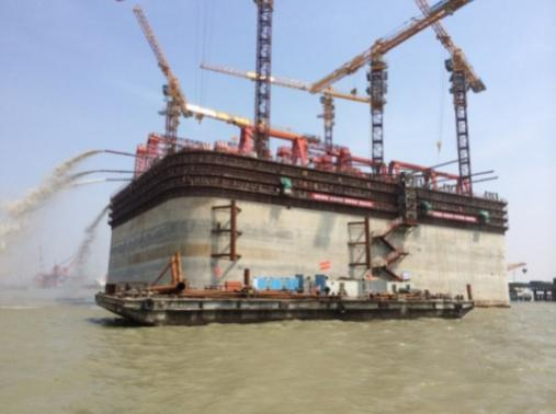
Fig. 3. Upper concrete caisson.
The size of an offshore bridge’s open caisson foundations are generally fairly large. If integral prefabricated caissons (concrete caissons) are utilized, existing mechanical equipment cannot be used for direct hoisting. If the method of pouring concrete after sinking the steel open caisson is adopted, any subsequent concrete construction will be very significant. At the same time, the operational risk is greater when more ships are involved and the time span is longer. If section construction is adopted, then, with respect to joint installation, design is the greatest technical challenge, and this technology has not yet been matured and perfected. Special projects are required for further research; in combination with the study of the offshore construction environment, the following technologies should be studied in advance:
(1) Technology for manufacturing and floating open caissons should be studied. In general, large caissons are manufactured near the bridge site to reduce the risks associated with long distance floating. Prefabricated assembly is recommended for the caisson segment jointing, which is lifted by a large floating crane and then cast-in-place with wet joints. At present, it is necessary to study the function and construction of the dock, well wall manufacturing, and caisson wall connection technology.
(2)At present, the main open caisson sinking methods in use are hydraulic suction machines and air suction machines; the cost of these methods are low. Multiple attempts have resulted in the reducing of the amount of side friction generated during construction, but attention should be devoted to further study of active sinking technology and remote control.
(3)Studies should focus on developing the application of underwater excavation equipment and underwater intelligent detection robots in deep water marine environments.
3.1.3 Large diameter steel pile foundation
For offshore bridges situated in thicker soil, large diameter steel piles are an important type of foundation used for bridge development. There are two methods of steel pile insertion: fixed guide frame with impact hammer (Fig. 4), and pile driving barge (Fig. 5).
《Fig. 4》
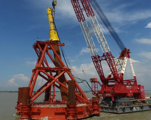
Fig. 4. Steel pile inserted by a fixed guide frame.
《Fig. 5》
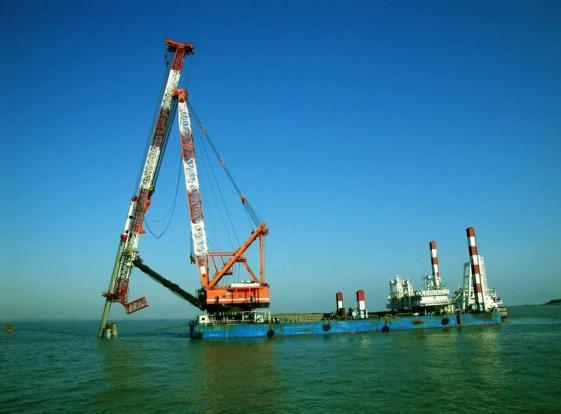
Fig. 5. Steel pile inserted by a barge.
Steel piles inserted by fixed guide frames have the following advantages. (1) High construction precision is provided. Generally, the inclination deviation of the steel pile is less than 1%, and the plane deviation is less than 50 mm through multi-layer guide adjustment. (2) Long pile construction equipment operating requirements are lowered; if an entire section cannot be constructed then it can be installed in segments. The main disadvantages are as follows. (1) The performance requirements and technical parameters of piling vessels are stringent; vessel stability is also a particularly important constraint. (2) Construction efficiency is low, the quantity of steel required is large, and guide frame installation requires a significant amount of time. (3) Adaptability is significantly reduced under ultra-deep water conditions.
The advantages of steel piles inserted by a driving barge [7] include the following. (1) Higher efficiency is provided as this method is three times more efficient than with fixed guide frame; the adjustment of the steel pile is relatively quick. (2) Water depth has little influence on pile foundation construction. (3) Adaptability to marine environment is better. The disadvantages include the following. (1)High performance and technical parameter requirements exist for the piling ship; ship stability is also an important constraint. (2)The vessel expense is relatively high as the mechanical equipment is more advanced. (3) The more steel piles found in a single pier, the greater the pile position directional change; this results in poor construction convenience.
For deep-water marine bridges, the application of large diameter steel piles requires further study of the following technologies:
(1) Carry out application test research on large-diameter steel piles of deep-water marine bridges and select a reasonable structural steel pile form. Anti-corrosion measures should be researched in depth.
(2) Improve the research and development of high-power hydraulic impact hammers and carry out application research on rapid-producing equipment of piling ships.
(3) Carry out research on equipment and process technology for soil extraction and pile bottom grouting.
《3.2 Research on the construction technology and upper structure development》
3.2 Research on the construction technology and upper structure development
3.2.1 Long-span cable-stayed bridges
Long-span cable-stayed bridges are a common structure found in marine bridges. The key technologies of the superstructure mainly include construction of the main tower, main beam, and stay cable.
At present, the creeping formwork technology of the main tower concrete has been relatively mature; it is essential to study template structure integration in the future. For combination mixed steel main tower structures, it is necessary to study mixed steel piece form, connection mode, and force transmission mode. From a rapid construction standpoint, we will develop construction tools with a high degree of automation and construction precision. We will also study new techniques for combining prefabrication and cast-in-place technologies.
For steel tower structures, design should be studied for welding, bolt, and bolt-welding combinations. The rapid construction technology of steel towers [8] mainly includes the long-section construction technology of large-scale tower cranes (Fig. 6), the long-section construction technology of large-scale floating cranes, or whole section vertical rotation construction (Fig. 7).
《Fig. 6》

Fig. 6. Large-scale tower crane lifting a subsection.
《Fig. 7》

Fig. 7. Large-scale floating crane lifting a subsection.
There are many forms for girders of large-span cable-stayed marine bridges including steel truss girders, steel box girders, and hybrid beams. The main girder is generally made from steel truss girders and is mostly in the form of double or triple trusses. There are several kinds of steel beam installation methods: bar assembling, truss unit hoisting, segment hoisting, and whole span hoisting. With the development of modern industrial equipment and science and technology, the steel beam manufacturing and erection process has made great progress. The Hutong Yangtze River Bridge currently adopts the double-section hoisting method (Fig. 8), and the Pingtan Railway Bridge uses full span hoisting technology (Fig. 9).
《Fig. 8》
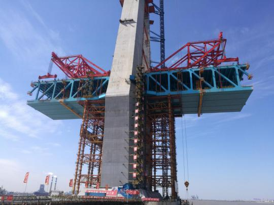
Fig. 8. Hoisting of double section Hutong Yangtze River Bridge girder.
《Fig. 9》
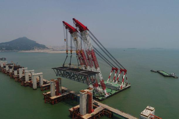
Fig. 9. 80 m full-span hoisting of the Pingtan Railway Bridge.
When marine ships are used for steel girder erection, wind, waves, and currents can seriously interfere with operations; hence, ship positioning can be a problem. At this time, to precisely maintain ship heading and positioning, the positioning should be managed by computer, in combination with various professional technologies [9].
Cables of cable-stayed bridges are anchored on towers and beams. There are many processes, such as cable-laying, traction, and installation, that are followed during construction. The installation of cable-stayed bridges requires larger lifting equipment, particularly as bridge spans increase. At the same time, more equipment is required as the traction force and traction distance increase. Therefore, an intelligent research direction regarding cable installation is development demand of ocean bridges.
3.2.2 Long-span suspension bridges
The long-span suspension bridge is the main structural form of the marine bridge; the steel tower and steel beam are the focus of future development.
The D5200 tower crane was used to install the steel towers of the Maanshan Highway Bridge, Parrot Island Yangtze River Bridge, and Yangsigang Yangtze River Bridge. Steel tower construction methods generally are of the following types. (1) The overall vertical rotation method. First, prefabricate the steel tower in the factory, transport it to the site, and then use lifting equipment or steering system to turn the tower into position. (2) The crawling crane frame method. This refers to using a climbing crane attached to the tower wall, with segments installed one by one. This method was used in the Shimazu Seto Bridge on Japan’s Benshi Contact Line and in the North-South Saito Seto Bridge; the maximum rated lifting weight of this method is 130 t. (3) The automatic lifting tower crane method. It can shorten the height of the tower crane by temporarily fixing the tower and the tower crane, enhance the vertical transportation distance of the tower crane, and obtain significant savings in equipment and manpower. The tower crane of the Mingshi Channel Bridge in Japan is a 160 t automatic lifting tower crane. (4) The floating crane large section frame method. A floating crane directly lifts the long segment, but the lifting weight and height of floating crane are limited to a certain extent.
The stiffening girders of suspension bridges generally adopt the form of a truss section, which is itself divided into sections according to the distance between suspenders. There are three installation methods of girder-erecting crane, cable-mounted crane, and floating crane. When erecting the truss unit (Fig. 10), the combination of the girder erecting crane and the girder transport vehicle can reduce the space of construction site to a great extent, but its speed is slow, and its susceptibility to wind is great. Cable-mounted crane method, which occupies fewer channels, is a common erection method of suspension bridge girders (Fig. 11). At present, the maximum lifting weight has reached 1000 t. When using the floating crane installation method, the floating crane requires more vessels for coordination, especially for the high technical requirements of the floating crane, and the equipment is generally larger. After sorting out, suspension bridge installation girders should be deeply studied; aspects of transportation positioning of stiffening girder, large-scale hoisting equipment, construction impact control of the main girder structure, and so on, should be studied in particular.
《Fig. 10》

Fig. 10. Girder chip by girder crane.
《Fig. 11》
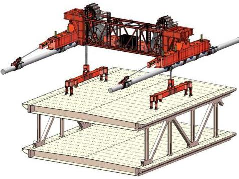
Fig. 11. Girder installation via cable-mounted crane.
The main cable of a suspension bridge is usually constructed by catwalk. The function of a catwalk is to serve as a construction platform for cable cope traction, cable adjustment, main cable fastening, cable clamp and sling installation, steel girder hoisting, main cable winding protection, etc. At present, catwalk construction research should focus on design, the erection of guide ropes, and on measures to increase stability to better withstand wind vibration.
The air spinning method was first used for main cable traction, and prefabricated parallel wire strand (PPWS) is the most commonly used method at present. Owing to the heavy rope tray of PPWS, large lifting equipment is needed. Therefore, the construction of the main cable storage site in the marine environment and its related influence need to be analyzed; main cable anti-corrosion technology also needs focus.
3.2.3 Intelligent information platform technology
Research on intelligent construction technology is an important means of realizing intelligent construction bridges. Through the integration of intelligent tooling centralization, construction monitoring, and standardization in construction, the building information model (BIM) can be used to deduce the construction plan in advance, verify the feasibility of the implementation plan, optimize construction sequence and resource allocation, and ensure that the project is safe, reasonable and economical. The main body and construction structure are modeled by BIM for construction; the project site, bridge construction area, and production workshop are arranged within the scene model. The overall project deployment is visually and intuitively displayed. Site operation safety and construction quality can be monitored from time to time within the office area.
《4 Conclusion》
4 Conclusion
In the past 20 years, China’s marine bridge construction has made remarkable achievements. However, in more complex and harsh marine environments, construction technology and related equipment of China’s offshore bridges will also face more new challenges. To improve construction efficiency and ensure the safety and quality of construction, the construction of offshore bridges in the future will be based on large-diameter steel piles, caissons, setting foundations, long-sections, or whole-span steel beams. With the development of large-scale construction and assembly, along with intelligent construction, a new age of construction technology for marine bridge engineering will take off.


 京公网安备 11010502051620号


