
《1. Introduction》
1. Introduction
Metamaterials are artificial structures consisting of massive subwavelength particles that are capable of manipulating the behaviors of electromagnetic (EM) waves. Many studies and explorations have been conducted on many aspects of metamaterials, including characterizations, theoretical analyses, designs, and applications, making them an interdisciplinary subject [1–6]. Early studies have treated metamaterials as effective media and focused on their physical properties. Several unprecedented phenomena (e.g., negative refraction [7] and invisibility cloaks [8]) have exerted significant influences worldwide and laid the foundation for early research on metamaterials. As thinner versions of metamaterials, metasurfaces have been presented to manipulate propagating waves [9–13] and surface waves [14–17]. Metasurfaces are composed of elements with gradient geometries to create gradient EM boundary conditions. However, the gradient boundary conditions are not the necessary conditions for tailoring the properties of EM waves. It has been shown by recently proposed digital coding and programmable metasurfaces (PMs) [18–22] that metasurfaces can be represented by finite types of elements and can be further abstracted into digital symbols. The spatial distributions of these symbols form different digital codes, which also determine the radiation properties of the PMs. Because the elements of the programmable metasurface are reconfigurable, the digital coding sequences can be dynamically switched. This spatiotemporal dynamic characteristic causes a PM to be an innovative technology in many EM fields [23–30].
The PM is also an innovative technology in the field of wireless communications. With the increase in massive data services in modern society, the communication spectrum becomes more crowded, forcing people to explore higher frequency bands and seek new technologies to achieve greater channel capacities and faster transmission rates. Massive multiple-input and multipleoutput (MIMO) technology has been considered one of the key technologies in fifth-generation (5G) wireless communication [31–36], but the high complexity of hardware hinders practical applications of massive MIMO in many scenarios. Although several hybrid technologies have been proposed to alleviate the complexity of massive MIMO [37–40], they are still complicated for costsensitive applications. As a new technology, the PM has been explored to realize a new architecture of wireless communication systems [41,42], in which special periodic subframes of digital codes in the time domain were designed to modulate the spectrum of the metasurface so that the information carried by the harmonics could be delivered. Detailed characteristics and possible challenges of the time-domain periodic subframes of digital codes have been addressed [43–46]. Another work used different farfield patterns of a PM to transmit the information, but many receivers placed at different positions were needed to recover complete far-field patterns [47]. Recently, 16 quadrature amplitude modulation (QAM) and MIMO transmissions have been realized at higherorder harmonics based on PMs [48,49].
PMs are also used as intelligent reflective surfaces to explore possible technologies beyond MIMO [50–58]. These works have studied different aspects of PMs, but they could not deal with digital modulations and wave manipulations simultaneously. In a previous work, we simultaneously modulated the amplitude of signals and near-field patterns based on a PM to realize multichannel transmissions of near-field information [59]. However, only amplitudes of near fields were modulated in that work, thus limiting application scenarios of the metasurface-based communication system. In addition, amplitude modulation signals have a lower anti-jamming capacity than phase modulation signals. This paper presents a complete design of far-field phase modulation communication based on a space–time coding metasurface, which greatly expands application scenarios of the metasurface-based communication system.
Specifically, we establish a new metasurface-based wireless communication system to achieve direct digital information transmissions in single-channel mode and multichannel modes. For the single-channel mode, the PM produces the main EM beam, and the digital information is transmitted and received in the main beam region. For dual-channel modes, the PM produces two main beams, and different digital information is transmitted and received through the two main beams independently. Compared with existing works that used periodic subframes to modulate EM waves, this work needs no subframes and hence greatly simplifies the design procedures. Moreover, this work provides a more flexible way to modulate field patterns and radiation phases simultaneously than existing works, which need extremely complicated subframes, especially for two-dimensional metasurfaces, as in this work. Based on the presented work, future wireless communication, imaging, and radar systems can be realized with greater flexibility, perfectly matching the multifunctional and intelligent trends of modern societies.
《2. Materials and methods》
2. Materials and methods
《2.1. Fundamentals of joint wave manipulations and digital modulations》
2.1. Fundamentals of joint wave manipulations and digital modulations
According to the Huygens–Fresnel principle, the far-field  radiated from the PM can be obtained by performing a Fourier transform on the aperture field
  . Hence, if the far-field is specified, the corresponding aperture field on the metasurface can be obtained by performing an inverse Fourier transform:

where  and
and  are distances between adjacent elements in x and y directions;
  is discrete-time interval;
  and
and  represent the spatial position of the mth and nth digital elements;
  represents discrete moment;
  and
and  are elevation and azimuth angles of the far fields, respectively.
If we introduce a phase term  to the same far-field pattern, another aperture field can be obtained as follows:

The two aperture fields produce the same far-field pattern but with different phases of the far fields. Using a modified Gerchberg–Saxton (GS) algorithm [26,58], two sets of phase-only digital codes corresponding to the two specified far-field patterns are obtained. By switching the two digital codes in a particular time sequence, the far fields can be modulated in the time domain, hence realizing wave modulations in the space domain and digital signal modulations in the time domain simultaneously.
With joint modulations of digital signals and far-field EM waves, the PM can transmit the digital signals to specified or desired directions. Supposing that the pictures or videos to be transmitted have been encoded to the digital signals that are further processed by quadrature digital modulations, then the digital signals are represented by two parallel branches: in-phase branch (I) and quadrature branch (Q), and each branch is a series of binary digits. For quaternary phase modulations, the instantaneous I/Q signals have four types of combinations (00, 01, 10, 11), corresponding to four types of phases. These phases can be directly realized by configuring the PM with adequate digital codes. Fig. 1(a) shows the process of metasurface-based wireless communications, in which the I/Q signals and the corresponding digital codes on the PM have been stored in a digital circuit board. By mapping the digital information of the pictures or videos to the I/Q signals, they can be transmitted through the PM to the desired direction(s).
In addition to realizing digital phase modulations, the PM can also realize beam steering when adequate digital codes are used. Fig. 1(b) shows the schematic of wireless communication with beam steering, which is useful in time-division multiuser schemes. On the other hand, the PM can simultaneously produce two beams in specified directions, hence enabling wireless communications in multichannel modes rather than only in the single-channel mode. Fig. 1(c) shows the schematic of communication in dual-channel mode, in which two users receive different digital information in two desired directions independently.
In the dual-channel mode shown in Fig. 1(c), the mapping operation is slightly different from that of the single-channel mode. In this case, the digital signals are represented by four parallel branches: the in-phase branch (I1 and I2) and the quadrature branch (Q1 and Q2). Hence, the combinations of these four branches are mapped to 16 digital codes of the PM, which radiate two-directional beams with different phases. Because the metasurface-based phase modulations are valid only in the area of the main beams, the two data streams are spatially separated. That is, the receivers in different directions receive different information independently.
《Fig. 1》

Fig. 1. Schematic diagram of the metasurface-based communications. (a) Direct transmission of digital signals by using the digital codes of the PM in a single channel pointing in the normal direction of the metasurface; (b) direct transmissions of digital signals with steered main beams; (c) direct transmissions of two different digital signals in dual channels pointing in two directions independently.
《2.2. Joint beam steering and digital phase modulation》
2.2. Joint beam steering and digital phase modulation
Detailed structures of the digital elements and the fabricated metasurface sample are given in Fig. 2. The fabricated PM contains 400 digital elements, and each element is composed of three metallic layers and two dielectric layers. The permittivity of the first dielectric layer is 2.65 with a height of 1.6 mm, and the permittivity of the second dielectric layer is 3 with a height of 0.2 mm. The top metallic layer integrates a pin diode (Skyworks 1320-079). By switching the pin diodes, the digital states of elements are dynamically changed. The middle metallic layer serves as a reflective surface of EM waves and as the ground of directcurrent (DC) signals. Two metallic cylinders are used to load DC voltages. The bottom metallic layer is a fan-shaped structure that chokes radio-frequency signals, so the DC feeding line has little effect on the radio-frequency performance of the element.
《Fig. 2》

Fig. 2. (a) Photo of the fabricated PM and the measuring environment; (b) detailed geometry of the digital element. DC: direct-durrent.
Before calculating the digital codes of the PM, the digital element is simulated using commercial software (CST Microwave Studio) to obtain reflection coefficients when the integrated diode is switched off and on. In simulations, the pin diode is modeled as an inductance (0.75 nH) and a shunt impedance (0.5 Ω) when it is turned on or an inductance (0.5 nH) and a series capacitor (0.24 pF) when it is turned off. The simulated reflection coefficient at 10 GHz is 0.861ej1.83π for the ‘‘on” state and 0.985ej0.8π for the ‘‘off” state. More detailed information on the element can be found in our former work [54].
Assuming that the far-field is a plane wave  in which k0 is the wave vector along the propagating direction of the plane wave, r is the vector distance and Φ is a constant. The results of beam steering and phase modulations are shown in Fig. 3. In Fig. 3(a), four types of digital codes on the programmable metasurface are designed to steer the far fields in the same direction (θ = 45 ° , φ = 0 ° ), but the value of Φ is increased linearly from 0 to 3 π /2 with an increment of π /2. Fig. 3(d) gives the calculated two-dimensional far-field pattern corresponding to the first digital code, showing that the main beam appears in the specified direction. Fig. 3(g) gives the measured far-field patterns of the four digital codes, demonstrating that the far fields are steered in the same direction for all digital codes. Fig. 3(j) records the measured phases of the main lobes, which are in excellent agreement with the specified values.
《Fig. 3》

Fig. 3. Results of beam steering and phase modulations. (a)–(c) Digital coding patterns for beam steering and phase modulations. The directions of beam steering are (θ = 45° , φ = 0° ) in (a), (θ = 0 ° , φ = 0° ) in (b), and (θ = –45° , φ = 0° ) in (c). For the three sets of digital codes, the phase modulations are from 0 to 3π/2 with an increment of π/2. (d)– (f) The corresponding far-field patterns in the UV coordinates (u = sinθcosφ, v = sinθsinφ). (g)–(i) The measured results of the far-field patterns. (j)–(l) The measured phases of the main lobes.
Similar processes are performed for the direction (θ = 0° , φ = 0° ), as shown in Figs. 3(b), (e), (h), and (k), and for the direction (θ = –45° , φ = 0° ), as shown in Figs. 3(c), (f), (i), and (l). For both cases, the directions of the measured main lobes have perfect matches with the specified values. The gains and phases of the main lobes corresponding to different values of Φ show some deviations, which mainly result from variant quantization errors of different digital codes, manufacturing tolerances, and uncertainties in the models. However, these tolerances do not significantly affect the performance of metasurface-based wireless communications, which has been verified by later experiments.
Although all digital coding patterns on the PM are obtained at a fixed frequency (10 GHz) and in a specified direction, the phase modulations remain valid in the vicinity of the specified frequency and direction, guaranteeing the robustness of the PM in simultaneous wave manipulations and digital modulations. Fig. 4 displays the tested far fields in an angular scope of 10° and a frequency range of 1 GHz. Fig. 4(a) shows the tested results when Φ = 0, and Figs. 4(b)–(d) show the phase differences referencing the value in Fig. 4(a). It is observed that the phase modulations are valid in the vicinity of the main lobes and the specified frequency. This is intuitive because the electromagnetic responses of the PMs are gradual. Moreover, the phase modulations are not valid in directions far from the main lobes. This is because the phase modulations are designed at the equiphase plane of the far fields. These important characteristics ensure that the phase modulations and wave manipulations are compatible.
《Fig. 4》

Fig. 4. Tested phases of the far-field when Φ is set to different values. The abscissa axis is the frequency range, and the ordinate axis is the angular scope. (a) Tested phase of the far-field when Φ = 0; (b) phase difference between the tested results when Φ = 0 and Φ =π/2; (c) phase difference between the tested results when Φ = 0 and Φ = π; (d) phase difference between the tested results when Φ = 0 and Φ =3π/2.
In addition to the phase modulations, the PM can also modulate amplitudes of the far fields by designing different digital codes. An example of binary amplitude modulation is demonstrated in Figs. 5(a)–(d). In Fig. 5(a), the far fields are steered to the normal direction of the metasurface, while in Fig. 5(b), the far fields are scattered randomly into space. Therefore, the field intensity of the far fields is controlled, and then binary amplitude modulation of the far fields is realized in the normal direction of the metasurface. Fig. 5(c) gives the tested amplitudes of the far fields in the normal direction of the metasurface and in a frequency range from 9.5 to 10.5 GHz. Fig. 5(d) gives the tested far-field patterns at different frequencies. The tested results validate the effectiveness of implementing binary amplitude modulations by a PM. Since phase modulations have some advantages in resisting noise in the environment, the digital signal modulations in the following discussions are chosen as the phase modulations.
《Fig. 5》
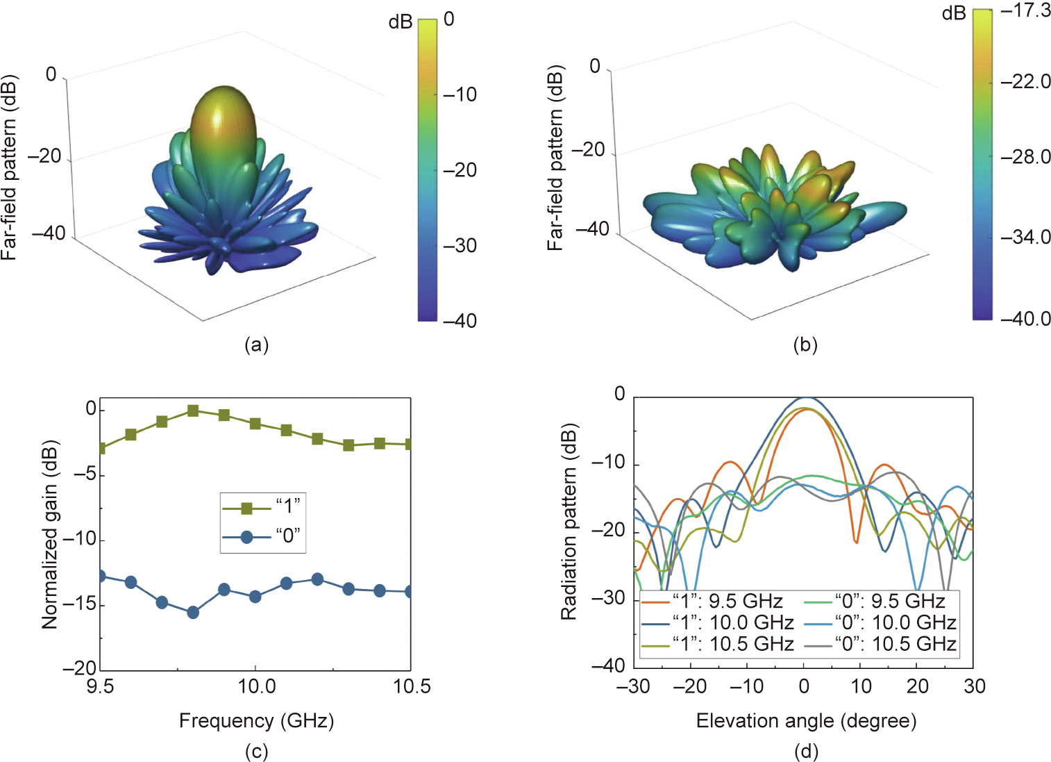
Fig. 5. Demonstrations of amplitude modulation. (a) The case of steering far fields to the normal direction of the PM, corresponding to digital signal ‘‘1”; (b) the case of scattering far-fields randomly into space, corresponding to digital signal ‘‘0”; (c) normalized gains of far fields in the normal direction at different frequencies; (d) radiation patterns at different frequencies.
《3. Results and discussion》
3. Results and discussion
《3.1. Independent joint digital modulations and beam steering in multiple channels》
3.1. Independent joint digital modulations and beam steering in multiple channels
Suppose that two-directional beams are produced by using the PM, that is,  . Correspondingly, the digital coding patterns of the metasurface are calculated by
  . It is clear that the radiation phases of the two beams can be controlled independently by setting different values of Φ1 andΦ2 . Figs. 6(a)–(d) present the far-field patterns calculated by arbitrarily specifying the beam directions, with Φ1 andΦ2 set to zero. The calculations show that the PM can steer the far fields in the specified multiple directions.
To interpret independent phase modulations in dual beams, four groups of Φ1 andΦ2 are specified to the far-field pattern, which contains two main lobes pointing at (θ1 = 10° , φ1 = 0° ) and (θ2 = –30° , φ2 = 180° ), respectively. For the first group, Φ1 remains zero and Φ2 increases with an increment of π/2. For the remaining groups, the same strategy is used, and only Φ1 is fixed to π/2, π, and 3π/2. The corresponding digital codes are given in Fig. 7. Figs. 6(e)–(h) give the measured far-field patterns of the four groups for the dual-beam case in Fig. 6(a), and Figs. 6(i)–(l) give the measured results of the corresponding phases of the main lobes.
For all groups, the measured far fields and phases are normalized to the values output in the case when Φ1 andΦ2 are set to zero. From the measured far-field patterns, it is observed that the main lobes swing in the vicinity of the specified directions when Φ1 andΦ2 are set to different values. However, the phase modulations remain valid in a certain angular range around the main lobes, guaranteeing the robustness of the PM in simultaneous wave manipulations and digital modulations. Variational intensities of received signals caused by swinging of the main lobes can be compensated by an automatic gain control (AGC) mechanism in the communication system.
The results in Figs. 3 and 6 show that the beamforming and digital modulations of the far fields can be simultaneously realized by using the PM, laying the solid foundation of metasurface-based wireless communication systems that are capable of transmitting digital information in both single-channel mode and multichannel mode.
《Fig. 6》
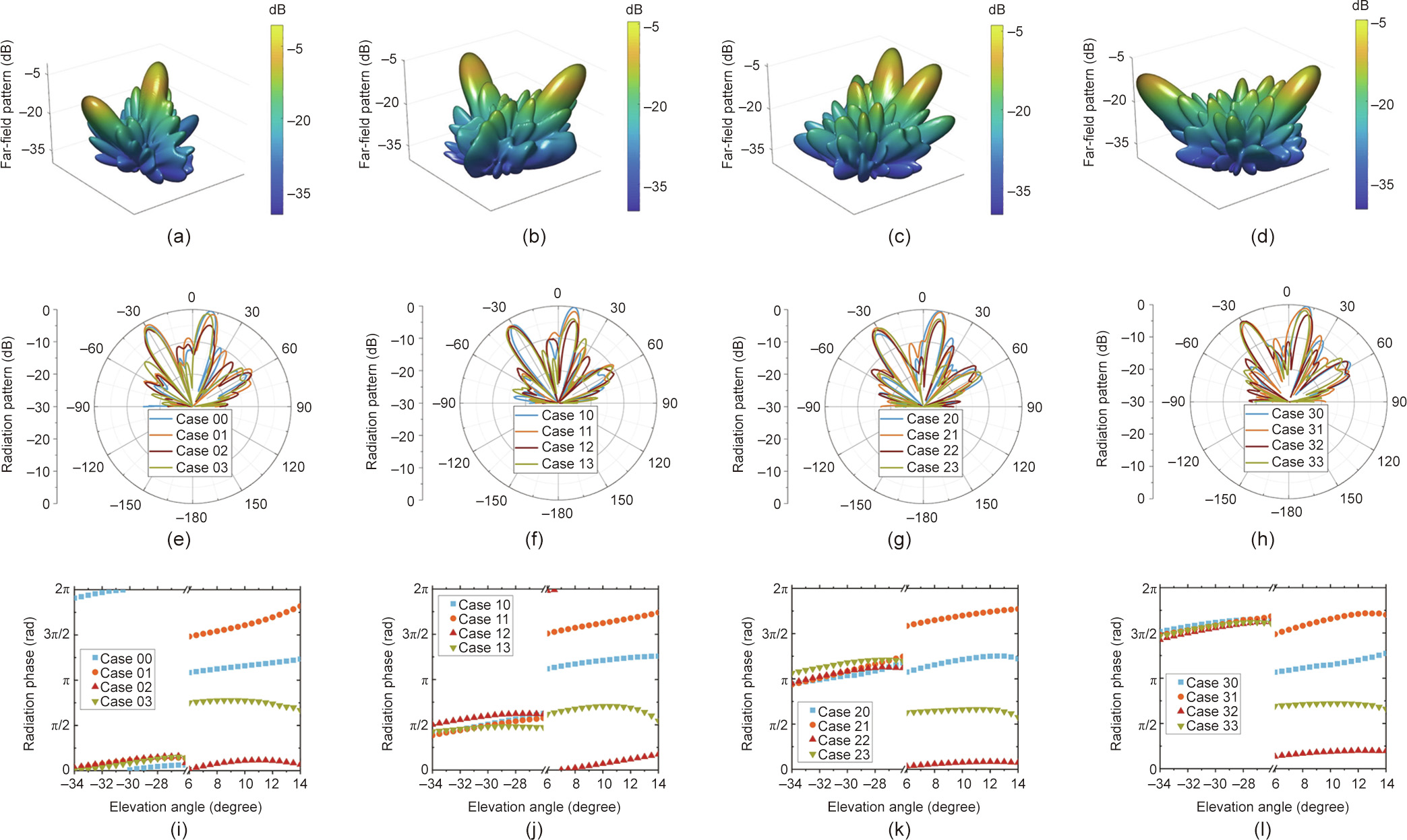
Fig. 6. Results of independent phase modulations of dual beams. (a)–(d) Calculated far-field patterns with two main lobes pointing in different directions. (a) (θ1 = 10° , φ1 = 0°), (θ2 = –30° , φ2 = 180° ); (b) (θ1 = 33° , φ1 = 86°), (θ2 = 29°, φ2 = 315°); (c) (θ1 = 25° , φ1 = 26° ), (θ2 = 28° , φ2 = 336°); (d) (θ1 = 43°, φ1 = 134°), (θ2 = 30° , φ2 = 310°). (e)–(h) The measured far-field patterns of the dual-beam case in (a) when the phases of the main lobes are independently specified. (i)–(l) The measured phases of the corresponding main lobes of the dual-beam case in (a).
《Fig. 7》

Fig. 7. Digital codes corresponding to different values of Φ1 andΦ2. Red squares represent elements in the ‘‘off” state, and green squares represent elements in the ‘‘on” state. For the first column, Φ1 remains zero and Φ2 increases with an increment of π/2. For the remaining columns, the same strategy is used, and only Φ1 is fixed to π/2, π, and 3π/2.
《3.2. Digital information transmissions based on a metasurface-based wireless communication system》
3.2. Digital information transmissions based on a metasurface-based wireless communication system
Here, we established a metasurface-based wireless communication system, and a schematic diagram and photo of the metasurface-based wireless communication system are detailed in Fig. 8. The whole system contains a transmitter, a receiver, and a computer. The PM is used to realize the joint modulations of EM waves and digital signals for the transmitter. A signal processing board (SPB, consisting of FPGA and AD9361) loads the digital information from the computer and then produces the corresponding digital codes of the PM. These digital codes are used to configure each element of the metasurface. SPB also produces a single-tone carrier (1.45 GHz), which is upconverted to 10 GHz to illuminate the PM. A standard horn antenna is placed for the receiver at a distance of 2.4 m to receive the signals. After downconversion from 10 to 1.45 GHz, the received signals are demodulated and decoded by SPB and finally delivered to the computer.
《Fig. 8》

Fig. 8. (a) Schematic and (b) photograph of the metasurface-based wireless communication system. SPB: signal processing board.
For single-channel wireless communications, the main lobe of the PM is steerable. We implemented wireless communication experiments in two different directions to verify this property, as shown in Fig. 9. In the first experiment, a photo picture of Guglielmo Marconi was transmitted and recovered through the main lobe, which is pointed at (θ= 0° , φ = 0°). In the second experiment, the main lobe was steered in another direction (θ= 10° , φ = 0°). Figs. 9(a) and (b) give the corresponding experimental results, showing good performance and verifying that the programmable metasurface can produce a steerable channel for wireless communications.
《Fig. 9》

Fig. 9. Experiments of the single-channel wireless communications. (a) The case when the main lobe points at (θ= 0° , φ = 0° ); (b) the case when the main lobe points at (θ= 10° , φ = 0°).
Fig. 10 demonstrates the experimental results of wireless communications in the multichannel mode. Photographs of James Maxwell and Heinrich Hertz were used as the information to be transmitted. First, these photos were encoded to frames in the media access control (MAC) layer, and each frame had 5844 bits. Second, 24 cyclic-redundancy-parity bits were added in each frame so that the receiver could judge the correctness of the received signals by implementing the cyclic-redundancy-check (CRC). The smaller the value of CRC, the less error the received signals have. Completely correct reception means that the value of CRC is zero. Third, the frame was encoded by low-density parity-check (LDPC) code, and another pilot sequence containing 1956 bits was added in the frame so that the receiver’s decoder can synchronize the received frames by performing convolutions on the pilot sequences. Finally, the whole frame was divided into four subframes. These frames were loaded into the digital circuit board and mapped to the digital codes of the designed PM. The switching speed of the digital codes is 10 MHz; hence, the transmission rate of the system is 10 Mbit·s–1.
《Fig. 10》

Fig. 10. Experiments of multichannel wireless communications. (a) Photograph of James Maxwell transmitted and recovered in the first channel in the direction (θ1= 10° , φ1= 0°); (b) photograph of Heinrich Hertz transmitted and recovered in the second channel in the direction (θ2 = –30°, φ2 = 180°). MAC: media access control; CRC: cyclicredundancy-check; LDPC: low-density parity-check.
In the designed experiments, the photo picture of James Maxwell was transmitted in one direction (θ1= 10° , φ1= 0°), and the photo picture of Heinrich Hertz was transmitted to the other direction (θ2 = 30°, φ2 = 180°). The receiver was placed at regions of the two main lobes to receive the photos. First, the receiver was placed around the direction (θ1= 10° , φ1= 0°), and a photo of James Maxwell was recovered by the computer, as shown in Fig. 10(a). Then, the receiver was placed around the direction (θ2= –30°, φ2= –180°), and the photo of James Maxwell was recovered by the computer, as shown in Fig. 10(b). The recorded values of CRC were zero when the receiver was placed in the right directions, indicating that the frame error rates of the metasurface-based wireless communication system were zero in both channels, which further validates the effectiveness and robustness of the presented wireless system.
More importantly, the same programmable metasurface can be used as single-channel wireless communications in a steerable way, dual-channel wireless communications in two arbitrary directions, and other multichannel wireless communications.
《4. Conclusions》
4. Conclusions
We presented a mechanism to fuse digital phase modulations and far-field manipulations simultaneously in programmable ways and practically established metasurface-based wireless communication systems to realize transmissions of digital information in single-channel mode and multichannel mode. The experiments validated the excellent performance of the wireless systems.
The novelty of the proposed metasurface-based wireless communication system includes the following: ① The modulations of EM waves and digital information are fused by the digital codes of the PM; ② the processes of the metasurface-based digital modulations are completely digitalized without involving any analog signals, and hence the digital-analog converters and mixers are not required; and ③ both single-channel and multichannel modes of the wireless communications are realized in the same PM platform, which can also be used for other multichannel cases. The EM wave, which is used to illuminate the PM, is a single-frequency wave produced by a separate radio-frequency link. This architecture enables deep digitalization and integration of metasurfacebased EM systems and makes the systems more flexible and easier to implement. Since modern electronic and information systems are evolving toward intellectualization and multifunction integration, the presented wireless system prototype will serve as a programmable platform for integrating intelligent and multifunctional functions such as wireless communications, radar, and imaging.
《Acknowledgments》
Acknowledgments
This work was supported by the Fund for International Cooperation and Exchange of National Natural Science Foundation of China (61761136007), the National Key Research and Development Program of China (2017YFA0700201, 2017YFA0700202, and 2017YFA0700203), the National Natural Science Foundation of China (6217010363, 61631007, 61571117, 61501112, 61501117, 61871109, 61522106, 61731010, 61735010, 61722106, 61701107, and 61701108), the Natural Science Foundation of Jiangsu Province (BK20211161), the 111 Project (111-2-05), and ZhiShan Young Scholar Program of Southeast University.
《Compliance with ethics guidelines》
Compliance with ethics guidelines
Xiang Wan, Chaokun Xiao, He Huang, Qiang Xiao, Wei Xu, Yueheng Li, Joerg Eisenbeis, Jiawei Wang, Ziai Huang, Qiang Cheng, Shi Jin, Thomas Zwick, and Tiejun Cui declare that they have no conflict of interest or financial conflicts to disclose.
《Authors’ contribution》
Authors’ contribution
Xiang Wan conducted the analytical modeling, numerical simulations, designs, and measurements. Chaokun Xiao and He Huang conducted parts of the designs and measurements of the communication system. Qiang Xiao, Jianwei Wang, and Ziai Huang conducted parts of the numerical simulations and measurements. Yueheng Li, Joerg Eisenbeis, Qiang Cheng, and Shi Jin conducted parts of the analytical modeling and designs of the communication system. As the principle investigators of the project, Wei Xu, Thomas Zwick, and Tiejun Cui conceived the idea, suggested the designs, and planned, coordinated, and supervised the work. All authors contributed to the preparation and writing of the manuscript.


 京公网安备 11010502051620号


