
《1. Introduction》
1. Introduction
Cloud manufacturing (CMfg) [1] virtualizes manufacturing resources and capabilities and builds an ultralarge shared pool of virtual resources that are delivered as services to consumers. This framework leverages new generation information and communication technologies (ICTs) and modern manufacturing technologies to develop the manufacturing industry. A cloud center usually has powerful storage, and networking and computing resources; however, the centralized processing or resource management in the cloud may lead to bottlenecks and large delays [2].
Edge/fog computing, a distributed computing paradigm that places computation and storage resources closer to the end things, can strengthen and complement CMfg to provide low latency, location awareness, mobility support, and real-time analytics [3–5]. As shop-floor production jobs are usually time-sensitive and involve proprietary information, real-time data regarding shop-floor tasks and objects can be processed at the edge nodes instead of being sent to the remote cloud. This framework can not only avoid network congestion but also facilitate real-time response and data protection. Thus, the utilization of edge/fog computing in CMfg should be explored.
Furthermore, resource scheduling plays a key role in CMfg by utilizing the resources integrated and pooled in the cloud to fulfill customer demands. Appropriate resource scheduling can increase the efficiency, reduce the resource consumption, and empower CMfg to deliver services with a high quality of service (QoS). In cloud computing, resource scheduling refers to the efficient assignment of computing, and network and storage resources, although resource scheduling in the manufacturing domain is primarily focused on allocating tasks to production machines to perform different types of production tasks. Many factors are driving the deep integration and exploration of research in the two communities [3]. Currently, two main limitations must be overcome to achieve high manufacturing efficiency and flexibility in the era of the Internet of Everything [6] and personalized products [7]:
(1) In manufacturing processes, machine tools, conveyors, and industrial robots are statically preconfigured and integrated in production lines [6], while the control software is closely integrated with the robot hardware that executes the movement. Consequently, it is time-consuming and costly to reconfigure, deploy, optimize, and scale factory automation to perform large-variety and small-volume manufacturing [8] and manage the various disturbances [9]. These drawbacks may also impede the implementation of more effective scheduling due to the static structure and configuration. However, structural changes (system reconfiguration) can be introduced to optimize the resource efficiency. In this context, separating the control software and executive hardware in the manufacturing system can enable fast system reconfiguration and reorganization for optimal scheduling.
(2) The widespread deployment of sensors and pervasive networking of manufacturing things enable the generation, collection, and transmission of manufacturing big data in the manufacturing system network. The existing research has focused on connecting things and makes decisions based on real-time data of the things [5]. However, with the increasing number of sensors and networked things, the large amount of heterogeneous raw data (zettabytes in the future) generated from various sources (e.g., numerous production machines) may lead to critical network congestion and hamper the overall quality of network services. Edge computing must be introduced to suitably clean and combine data at different levels to reduce the data traffic in the network. Moreover, the pattern of data traffic is not stable because manufacturing tasks are allocated to different production machines and generate different data traffic on the network; therefore, efficient collaborative production requires flexible control of data streams among machines in networks [10]. Thus, software-defined networking (SDN) featuring flexible networking should be explored in network traffic control, considering time-sensitive data transmission, to reduce the communication delay and increase the collaboration efficiency [11]. In addition, task allocation and flexible data flow control must be considered in scheduling.
The contributions of this work can be summarized as follows. To address the abovementioned issues, a new SDN-based model of CMfg [12], including the definition, architecture, and principle, is proposed. This model can help eliminate the tight vertical and horizontal coupling of manufacturing resources and realize flexible resource scheduling in the CMfg environment. From the network perspective, the traditional CMfg model can no longer meet the data communication requirements associated with pervasive sensing, data interaction, and large-scale collaboration of manufacturing things. In this paper, a new model is introduced to solve the network traffic control problem in a manufacturing system for complex manufacturing tasks. Based on the abstraction and virtualization functions of the software-defined cloud manufacturing (SDCM), we formalize the time-sensitive data traffic control problem considering subtask allocation and data routing path selection. To solve this optimization problem, the genetic algorithm (GA), Dijkstra’s path algorithm, and a queuing algorithm are integrated and used. The experimental results demonstrate the effectiveness of the integrated approach in satisfying the time constraints and reducing the total communication latency.
The remaining paper is organized as follows. Section 2 reviews the relevant literature; Section 3 describes the concept and reference architecture of the new model; Sections 4 and 5 formalize the traffic control problem and introduce the problem-solving approach; Sections 6 and 7 describe the experiments and present the concluding remarks.
《2. Related work》
2. Related work
《2.1. Cloud-based manufacturing》
2.1. Cloud-based manufacturing
The potential of cloud computing in manufacturing was first explored under the CMfg terminology [12]. Ren et al. [13] presented key characteristics of CMfg frameworks and proposed a four-process multiagent collaborative model that first clarified the complex operational mechanisms of CMfg cyber–physical systems. Simeone et al. [14] developed an intelligent decision support tool based on a manufacturing service recommendation system to recommend tailored manufacturing solutions to customers through a CMfg system. Mourtzis et al. [15] proposed a cloudbased knowledge-enriched framework that consisted of a monitoring system, a knowledge-reuse mechanism, and an optimization system to increase the machining efficiency. Liu et al. [16] proposed a framework based on deep reinforcement learning for scheduling in CMfg and demonstrated its effectiveness for online single-task scheduling. However, cloud-centric manufacturing architectures cannot support real-time responses from the cloud for shop-floor applications at the network edge because of the large distance between the cloud and shop-floor things and the unpredictable network performance [3]. Queiroz et al. [17] used a multiagent systems approach, rather than centralized cloudbased artificial intelligence (AI) approaches, to design cyber– physical agents that could embed different data analysis capabilities and support the decentralization of intelligence. In this way, fog/edge computing [18] can strengthen cloud-based manufacturing with fast edge processing capabilities [4,5]. He et al. [19] proposed an evolution-oriented microservice programming framework in cloud–edge environments to enable self-adaptation and the optimized evolution of the service system. Other collaborative cloud–edge processing approaches for shop-floor data using AI algorithms were proposed for data-driven smart diagnosis services [20,21]. Novel industrial AI models such as semi-supervised parallel deep factorization machine (SS-PdeepFM) model [20] and the wide–deep-sequence model [22] were proposed to establish deep neural networks for heterogeneous industrial data with low quality and considerable noise. For example, the wide–deepsequence model [22] first realized the cross-domain integrated learning of multidimensional heterogeneous industrial data with hidden coupling relationships in the Industrial Internet of Things (IoT). Ren et al. [23] proposed a novel cloud–edge lightweight neural network model to enhance the algorithm time efficiency with no loss in the prediction accuracy. Ren et al. [24] proposed a generative-coding group evolution (GCGE) algorithm with collaborative cloud–edge intelligence to enhance the efficiency and stability in the large-scale task assignment associated with the Industrial IoT. However, the scheduling of network resources, which is vital for seamless human–machine and machine–machine collaboration, has not yet been extensively examined in the context of cloud-based manufacturing. For complex manufacturing tasks, subtask allocation can affect data traffic patterns among network links and should be properly managed to facilitate efficient collaborative manufacturing. Against this backdrop, edge computing that can provide rapid responses to manufacturing things in the workshop with computing, data caching, and data forwarding capabilities should be explored in flexible resource scheduling.
《2.2. Software-defined network》
2.2. Software-defined network
The pervasive connection, high data throughput, and volatile traffic patterns among manufacturing things necessitate finegrained network resource management, and SDNs represent a promising solution as they can separate the control plane and data plane in the network and logically centralize the control through a remote SDN controller [25]. The primary goal of SDNs is to increase the flexibility of networking [25]. Hu [26] proposed a system architecture for software-defined Industrial IoT to ensure the software definability of key architectural elements. Salahuddin et al. [27] proposed a roadside unit cloud as a vehicular cloud for the computational and communication infrastructure. The deep programmability of SDN was leveraged to dynamically reconfigure the services and the corresponding data forwarding information to efficiently serve the underlying demand from the vehicle grid. Naeem et al. [28] proposed a novel model-free SDN-based adaptive deep reinforcement learning framework based on a fuzzy normalized neural network to address the issue of congestion control in IoT networks. These studies provided a valuable basis for research on smart, efficient, responsive, and robust CMfg frameworks. However, from the overall standpoint, the existing methods pertaining to CMfg cannot support fine-grained network resource scheduling (for efficient collaborative manufacturing) or function programmability, which are critical for system agility and fast responses [3]. Thus, a new trend is to combine the advantages of SDN, edge computing, and cloud computing to realize more effective network control and management [2].
《3. Software-defined cloud manufacturing》
3. Software-defined cloud manufacturing
《3.1. Definition》
3.1. Definition
Manufacturing, which was constrained by hardware and logistics in the past, is presently being reshaped into an activity defined mainly by software [29]. With the introduction of IoT and cyber– physical systems, physical things are being networked and transformed into cyber-entities, indicating a shift to the digital world. Software, rather than hardware, has become the dominant part of many systems [5,11]. Against this background, SDCM is proposed, which can serve as a new foundation for the future manufacturing sector.
SDCM is a new model of CMfg that integrates SDN and other newly emerging ICTs. The model can be leveraged through the software-defined (programming) way, to describe, simulate, integrate, configure, empower, manage, execute, accelerate, and innovate manufacturing processes and other related elements in manufacturing activities.
As shown in Fig. 1, the SDCM can act as a new model that can use virtualization technologies to disrupt the tight vertical integration of hardware and software, separate the control logic of manufacturing resources from the underlying hardware resources, and facilitate the logical centralization of hardware control. Through these features, the model can realize software based programming of the manufacturing resources or systems. The SDCM has several advantages as follows.
《Fig. 1》
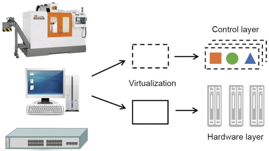
Fig. 1. Disrupting the vertical integration of software and hardware.
First, the SDCM can flexibly combine and separate physical manufacturing resources into independent end-to-end logical slices through its core enabling technology (resource virtualization and function programmability). Subsequently, the model creates an open programming environment for engineers. Through the functional programmability, different levels of software development kits (SDKs) can be provided and utilized to operate the resources at different hierarchical system levels [1]. This setting can increase the agility required to accelerate the upgrade and operations of the manufacturing system and facilitate resource sharing and utilization.
Second, in the SDCM framework, the integrated manufacturing resources can be networked and organized in a user-centric, fast, flexible, and collaborative way by programming the control and management logic in software controllers. The controllers can respond in time to both external and internal disturbances and manage manufacturing processes in an efficient and effective way. Furthermore, consumers can write codes that can automatically access, configure, orchestrate, and manage virtual manufacturing resources to realize the desired functions and capabilities.
Third, the SDCM system is smarter because the intelligence (control logic) that oversees automation hardware is transferred from hardware to software, and software can progressively learn to become smarter through information regarding the manufacturing system and environment. Therefore, smart manufacturing becomes a continuous process that can be autonomously updated, enhanced, and improved through data and intelligence.
《3.2. Reference architecture》
3.2. Reference architecture
A reference architecture for SDCM is proposed through the incorporation of SDN [11] to make the cyber–physical manufacturing system programmable and controllable via software (Fig. 2).
《Fig. 2》

Fig. 2. Reference SDCM architecture. SDVEs: software-defined virtual entities; GWs: smart gateways; OS: operating system.
The first layer is the abstraction layer of physical things. Manufacturing machines/resources function as cyber–physical interfaces can be programmed in the cyberspace to provide various functionalities in the physical world. These basic objects, such as robots and sensors, on the network edge are named atomic hardware. The IoT and smart SDCM can promote the digitalization of such atomic hardware, and software can be used to enhance the implementation of smart decisions and realize customized and personalized production.
The second layer is the smart gateway (GW) layer. GWs may be either embedded computers that can oversee and control atomic hardware or edge computing nodes that can place computation and data storage facilities closer to the location in which they are needed to reduce the response time and bandwidth for nearby data sources or shop-floor things [35]. To promote unified resource management, virtualization technology, and service-oriented architecture can convert heterogeneous atomic hardware through abstraction and GW layers into software-defined virtual entities (SDVEs) in the cyber world.
The third layer is the SDVE layer. This layer consists of SDVEs with application programming interfaces, programming models, libraries, and development tools. Each SDVE usually has limited hardware resources and should thus be able to manage its task list in a well-organized manner. As such SDVEs can be flexibly defined, programmed, and organized, complicated control logic for various goals can be realized. For example, by building a layer of robot operating systems (OS) on the production robot, on which personalized modules supporting customized production can be deployed, the openness and evolvability of the robot can be improved.
The fourth layer is the SDN layer. SDN makes networks more programmable and flexible by separating the control plane from the data plane. On this layer, the SDN controller supervises the virtual network and dynamically adjusts the resource allocation to meet the diverse QoS requirements of manufacturing applications. The network of manufacturing things (i.e. SDVEs) can be flexibly configured to facilitate efficient interactions and collaborations according to application requirements, such as to configure suitable paths among parts (of the end product) and industrial robots.
The fifth layer is the ultraflexible manufacturing service layer. To organize the SDVEs and form an efficient collaborative network for complicated assignments, the SDN management renders the network configuration more efficient and enhances the network performance among virtual resources. This framework can satisfy the industrial communication needs for different QoS values and promote efficient collaborations among the SDVEs. Moreover, the network of SDVEs can be monitored and flexibly programmed to meet the application requirements. In addition, this layer provides SDKs to develop platforms or applications.
The sixth layer is the manufacturing application layer. On this layer, the application software can be programmed based on platform SDKs or ultraflexible manufacturing services by stakeholders such as engineers and end users to jointly fulfill manufacturing tasks.
These six horizontal layers involve three significant aspects. The first aspect pertains to the industrial big data collected from workshops, factories, supply chains, and logistics systems by IoT devices or from the internet. Using AI technologies, big data is utilized to obtain knowledge or information to ensure that smart decisions can be made for different levels of applications. Real-time data processing is implemented in embedded computing units of manufacturing machines or edge computing nodes to achieve faster responses, whereas offline big data analytics is conducted in the cloud to acquire global and comprehensive views and insights. The second aspect, pertaining to security and privacy, is crucial in the highly connected and open world because ubiquitous sensing, connection, and control may lead to critical issues regarding reliability, security, and privacy. Hackers may exploit bugs to perform widespread cyber-attacks [30]. As industrial big data are collected and stored in the cyber world, these aspects may lead to privacy and data security problems. Thus, industrial systems and data should be protected with measures considering the balance between efficiency and privacy. Finally, device–edge–cloud collaborative processing is essential in the SDCM, not only because outstanding cloud storage and computing abilities are needed to analyze big data and support optimal decision-making in the manufacturing processes, but also because fog/edge computing nodes (GWs) [4] near the end things can help strengthen, extend, and complement the SDCM with low latency, location awareness, mobility support, and real-time analytics [31]. Therefore, edge– cloud collaborative processing approaches are necessary to deliver diverse services for end things or user tasks.
《3.3. Flexible resource scheduling for the SDCM》
3.3. Flexible resource scheduling for the SDCM
Supported by the architecture, the manufacturing, computing, and network resources can be virtualized and dynamically configured to be end-to-end logic units, according to the industrial requirements. This framework lays a foundation for disrupting the close coupling and collaboration between resources to ensure that the SDVEs and virtual networks can be flexibly organized, configured, and combined to form an efficient manufacturing system. This setting helps release the resources from the statically preconfigured manufacturing system and exploit the potential of resources with a larger scheduling space. For resource scheduling optimization, the real-time status of manufacturing devices and things is monitored and recorded as industrial big data, which are processed and analyzed through device–edge–cloud computing. The results can be used to make smart decisions regarding the dynamic configuration of collaborative logic units. For customized and personalized production orders, the SDVEs can be rapidly programmed and repurposed for special functions. The virtual networks enabled by the SDN can also be programmed and configured according to the communication requirements of the collaborative SDVEs. Thus, highly flexible resource scheduling can be realized.
Overall, the SDCM can satisfy the demands of the future manufacturing industry for speed, scale, flexibility, and openness. We apply the SDCM to solve the traffic congestion problem in a manufacturing system.
《4. Problem formulation》
4. Problem formulation
《4.1. Problem description》
4.1. Problem description
As more manufacturing things and machines become connected to form a collaborative network, the data interaction between any two objects necessitates flexible and fine-grained network resource scheduling to achieve a high collaboration efficiency and low communication latency. Therefore, the SDCM is adopted to separate the data plane and control plane in the manufacturing system network. For such flexible networking environments, it is beneficial to develop a more effective network resource allocation method on the control plane to ensure low-latency data transmission from a global perspective.
《4.2. Problem formulation》
4.2. Problem formulation
A complex manufacturing task can be referred to as a CMT. A CMT includes multiple manufacturing processes, each of which can be completed on a certain type of manufacturing machine. Each atomic manufacturing machine can be abstracted, virtualized (according to its operation logic and function), and networked to be an SDVE (i.e., a manufacturing unit (MU)). To ensure efficient collaboration in performing tasks, data and information must be transmitted through the SDN among manufacturing resources (e.g., MUs and edge computing nodes/GWs).
4.2.1. MUs for different types of tasks
In an SDCM system, different MUs can sequentially or simultaneously perform different types of manufacturing processes. Therefore, for a complex task consisting of multiple processes denoted by CMT =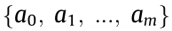 (where m is the number of processes), any process denoted by
  ( i = 1, 2, …, m )corresponds to a specific category pi
  P = { type1, type2, …,typeL (where L is the number of process types), and the manufacturing process of each category can be accomplished by one or more MUs that can perform this type of process.
The set of actuators (manufacturing machine) can be denoted as SDVESet = {c1, c2, ..., cL}, and each element of the set denoted by cj (j = 1, 2, ..., L) corresponds to the set of MUs 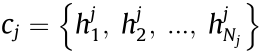 (where Nj is the number of such units), which can implement a process of the typej category.
Therefore, when selecting the execution unit for each process  (i = 1, 2, ..., m) in the manufacturing task, the search should be conducted in the corresponding set of MUs cj* according to pi (assuming pi = typej*).
4.2.2. Network communication model
For a complex manufacturing task CMT = 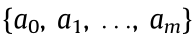 and execution unit for each process (with the MU assigned for defined as hi), the procedure to fulfill a CMT can be represented as a pair of dual numbers: {(h0 h1), (h1 h2), ..., (hm-1 hm)}, including (m + 1) processes. These processes are completed on (m + 1) MUs. A total of m information transmissions occur during the whole process since the necessary data and information must be transmitted between two adjacent processes.
In an SDCM system, the communication network connects the MUs and GWs, and the corresponding topological graph can be denoted as GRAPH (V, E), in which V is the set of network nodes (including MUs and GWs), and E is the set of connections (edge) among network nodes. As shown in Fig. 3, A, B, C, D, I, and J are MUs, while E, F, G, and H are GWs. Assuming the presence of a wireless connection or wired cable for data transmission between two interconnected nodes, the resulting wireless, wired or hybrid network can be virtualized (as SDN) to provide network slices to manage the diverse sets of requirements for networking. In other words, the network resource is time slotted as network slices to be utilized for fine-grained network resource scheduling, an idea similar to ‘‘time division multiplexing.” Moreover, the data routing path can be selected and controlled by the SDCM network to reduce communication latency.
《Fig. 3》

Fig. 3. Topology of a manufacturing system.
Before being transmitted in a channel, the data are broken down into similar structures known as packets. The packet transmission time in communication channel k (edge k in graph GRAPH) is denoted as  . A wider channel bandwidth corresponds to a higher rate of data transmission and smaller . Therefore, the total transmission time of data dt(
 ) with data packets in the channel is
  .
.
For a manufacturing task set CMTSet = {CMT1, CMT2, ..., CMTn}, the start time of the jth process of the ith CMT is  (that is, the instant at which the MU assigned to perform the jth process receives the required data), the MU that executes the jth process is hi,j and the end time at which the process is completed is
  . The generated useful data when the jth process is completed must be transmitted to the MU hi,j+1 for the next ((j + 1)th) process.
If the selected routing path of data dt( ) (including data packets) transmitted from the MU hi,j to hi,j+1 is
  → … →
→ … →  →
→  , the data pass ( r – 1 )( r ≥ 1) intermediate nodes. The arrival and departure times of the data in every node in the selected path are
  and
and  (p = 0, 1, 2, ..., r), respectively. Therefore,
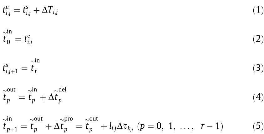
where  is the execution time of the jth process of the ith CMT;
  is the waiting time when the data
  (to be transmitted) queues up in node
  ; specifically, when the data
  arrive at node , they must wait in the queue of data to be transmitted and can only be transmitted after the data in front have been transferred in this channel;
  is the total transmission time of the data ;
  represents the transmission time when a single data packet is transmitted from node to node
  . Therefore,
where  represents the number of data packets queuing in node head of data ;
  represents the number of remnant data packets of the qth data queuing up; and
  represents the rest time for the data packet transmission to be completed when data arrive at node , 0 ≤ <.
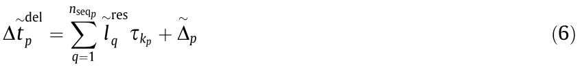
The value of  can be calculated using Eqs. (1)–(6),
  , and transmission path of data :

Furthermore, assuming  =0 (i = 1, 2, …, n), we can calculate the execution time and
  (i = 1, 2, …, n ; j = 1, 2, …, mi) of every process in every CMT.
4.2.3. Constraints of time and capacity
(1) Time constraints for the data transmission. For the jth process of the ith CMT, the data traffic (number of packets of data)  and upper time limit
  of the time-sensitive data transmission can be determined. Therefore, the selected data transmission path must satisfy the demands of the time constraints of data transmission:
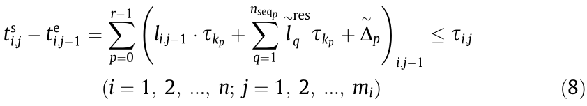
where  in Eq. (8) represents the process of data transmission from MU
  to
to  in the ith CMT.
(2) Upper limit of tasks performed simultaneously by an MU. There exists an upper limit on the number of tasks an MU can simultaneously perform. The set of MU in the whole SDCM system is denoted as H =  , and N is the number of MUs. The upper limit of tasks that any MU i can simultaneously perform is denoted as Ci ( i = 1, 2, …, N ).
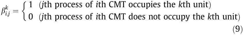
In addition, wi,j indicates the workload of the jth process of the ith CMT, and  represents whether the jth process of the ith CMT occupies the kth MU. Note that is a 0–1 integer variable.
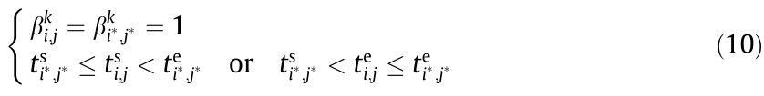
Therefore, for each process of every given task, it is necessary to identify the processes that require the same MU and overlapping execution time. The set of these processes is denoted as Neighbori,j( i = 1, 2, …, n; j = 1, 2, …, mi ). The approach to determine Neighbori;j is as follows.
First, select the j*th process of the i*th CMT, the time interval of which can be determined as  according to the abovementioned approach. Second, traverse all the processes in all manufacturing tasks in CMTSet. If a process (the jth process of the ith CMT) satisfies the demand of the relationship, as shown in Eq. (10), it can be added to
  (the j*th process of the i*th CMT itself is also included in the set , in accordance with the current rules).
The selected MU should comply with the upper limit of simultaneously executable tasks:

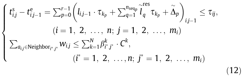
4.2.4. Optimization model
The ultimate goal of this model is to properly select the MU for every process of a given manufacturing task and data transmission path between the MU for two adjacent processes in the same manufacturing task to ensure that all the given tasks can be finished in the least time. The time constraints are associated with the data transmission and upper limit of simultaneously executable tasks of each MU. Therefore, the optimization model can be built as Eq. (12).

Subject to
《5. Problem solving algorithms》
5. Problem solving algorithms
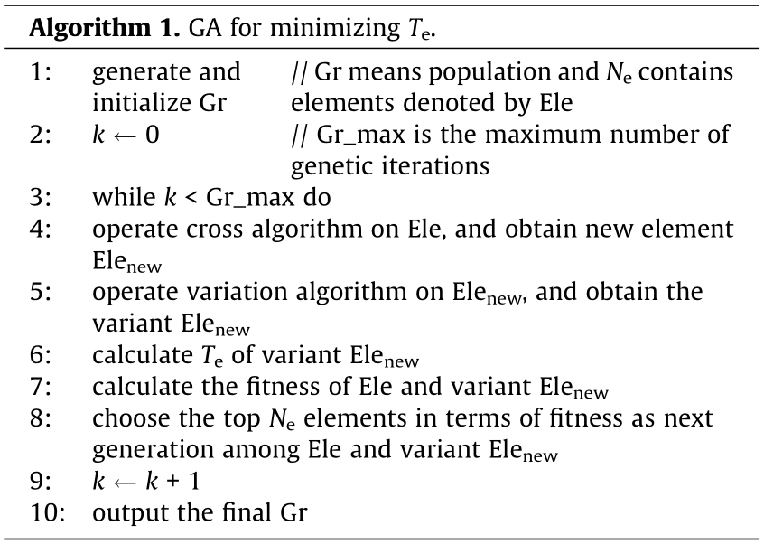
As a stochastic search algorithm, GA has two notable advantages: the ability to address complex problems and parallelism [32]. To solve the considered optimization model, a GA is used to optimize the selection of MUs in different processes of each manufacturing task. Subsequently, Dijkstra’s shortest path algorithm is used to find the shortest path of data transmission between two adjacent processes (MUs) in a manufacturing task. If other manufacturing tasks need to use a channel currently being occupied by a task, an improved queuing algorithm considering the rest time limit of data transmission can be used to transmit data in sequence. Here, channel occupation refers to the state in which the channel (network) between the source and destination nodes is currently being used for data transmission for a manufacturing task. If other tasks need to transmit data in this channel, the data packets to be sent are required to queue up in the source node. Two or more tasks can share the same channel, and each task uses the channel exclusively in different time slots. Algorithms 1 and 2 show the structure of the GA and the algorithm framework to calculate the completion time Te of a manufacturing task with a given genotype (MUs for all processes of all manufacturing tasks), respectively. Since this model mostly focuses on data transmission, the maximum working capacity of MUs is neglected, and only the transmission time constraint is considered to determine whether the constraint conditions are satisfied in Algorithm 1.
(1) GA. For each process of each CMT in the task set, after selecting the MU, the data transmission path and sequence of data in the queue can be determined according to the following approach. Moreover, the adherence to the constraints can be evaluated, and the completion time at which all tasks are finished can be determined.
In this research, a GA is used to obtain the optimal plan of MU allocation. Every manufacturing process of all CMTs is set as a locus, and the total number of loci is  sum of CMTi ' s subtasks. According to every process type, the corresponding locus can choose its value as the sequence number of the MU in the MU set (MUs having the same type as the process are numbered in a specified order in the set).
To obtain the optimal values in the optimization problem, the algorithm adjusts the fitness of the individual according to the genotype differences between the individual and other individuals in the population. Eq. (13) is used to calculate the individual fitness, where d represents the average difference in the genotypes for an individual and others in the population, and D represents the corresponding difference among all individuals in the population. d and D are calculated using Eqs. (14) and (15), respectively. Te is the performance trait of an individual genotype (namely, the task execution time, given the selection plan of MUs; if the plan selected cannot meet the constraints, the execution time equals the sum of the original execution time and a large value M). Te_min is the corresponding execution time of the optimal individual (solution) in the population.

In Eqs. (13)–(15),  is a non-zero small positive number, Ne is the population size (total number of individuals in the population), genetic_sum is the number of individual loci, and
  is the value of the jth locus of the ith individual in the population.
(2) Path algorithm. Dijkstra’s path algorithm can be applied to find the shortest path between two given nodes (MUs) when Algorithm 2 selects the data transmission path for each process of all CMTs.
The distance between the edges of two directly connected nodes (kth edge in the network topological graph GRAPH) is the time  required for the transmission of a single packet, while the distance between two nodes that are not directly connected is set to a large value LD
  .
.

(3) Queuing algorithm. After the transmission of the current data in a channel, the sequence of other data to be transmitted is arranged according to the time  to the deadline. The data with the smallest are transmitted first. is calculated as
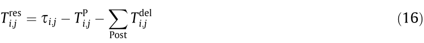
where  is the propagation time of the jth data transfer of the ith CMT, and
  is the time required for the previous transmission process of these data.
《6. Experiments and analysis》
6. Experiments and analysis
The numerical experiments are performed using the model and algorithms in two kinds of network systems: ① a classic and simple network (ten nodes, with six execution unit nodes and four intermediate nodes) shown in Fig. 3 and ② a randomly generated network system, denoted as Sys(num, prob), where num represents the number of nodes in the network topology, and prob is the connection probability between two nodes. The simulation experiment is conducted using Visual Studio 2019 C++, with num = 20 (12 execution unit nodes are randomly selected from 20 nodes) and prob = 0.25.
The given manufacturing task set CMTSet in the simple network system is different from that in the complex network system. In the simple and complex networks, the CMTSet contains five CMTs and ten CMTs, respectively. In each CMTSet, the execution time of different processes is set as zero (representing values much less than the data transmission time), value approximately equal to the data transmission time, and value exceeding the data transmission time (three times higher than the data transmission time).
The transmission time of a single data packet in the network channel is set as 0.1 ls, and that of the data (composed of several data packets) is set as approximately 0.1–1.0 ms. Therefore, the time limit of data transmission between two MUs is set as 1 ms.
The relevant parameters and their settings are listed in Appendix A Tables S1–S6.
《6.1. Result analysis of a simple network》
6.1. Result analysis of a simple network
For the simple network, three groups of experiments are conducted according to the different execution times of the process: no execution time (NET)—the process execution time is zero; short execution time (SET)—the process execution time and data transmission time are of the same magnitude; and long execution time (LET)—the process execution time is three times larger than the data transmission time.
Fig. 4 shows whether the MU selection plan randomly generated in the three groups of experiments satisfies the time constraint. When the process execution time is much less than or approximately equal to the data transmission time, the average probability of the plan meeting the time constraint is extremely low, only approximately 1%, mainly due to the tight time constraints. However, if the process execution time considerably exceeds the data transmission time, since the data transmission is more scattered in the time dimension, the channel occupation rate is lower. In other words, the waiting time in queues for data transmission is lesser, and the average probability (approximately 14%) of meeting the time constraint in the random experiments is significantly higher.
《Fig. 4》
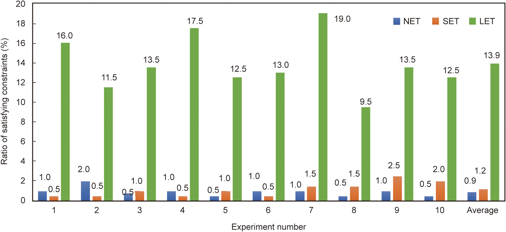
Fig. 4. Constraint satisfaction rate of random plans in the simple network.
Fig. 5 shows the comparison between the randomly generated ‘‘optimal” plan and solution obtained using the proposed algorithms in the three groups of experiments. The ordinate is the total communication time (difference in the maximum value of the task completion time and total execution time of all the processes in a CMT, including the data transmission time and queuing time). The experiments show that the minimum communication duration in the converged solution obtained by the GA is considerably smaller than that in the randomly generated plan regardless of the execution time. In the simple network, the algorithm solution always converges to a superior or the optimal solution.
《Fig. 5》

Fig. 5. Minimum total communication time of optimal solutions in the random solution and algorithm solution in the simple network.
《6.2. Result analysis of a complex network》
6.2. Result analysis of a complex network
Compared with the number of tasks in the simple network, the number of tasks in CMTSet is higher in the complex network (the number of nodes in the complex network is two times as many as that of the simple network, and thus, the number of CMTs in the complex network is doubled). Moreover, the time constraints are appropriately relaxed, and three sets of numerical experiments are conducted according to the different execution times of the manufacturing processes.
Fig. 6 shows whether the random plan satisfies the time constraint, and Fig. 7 shows the comparison between the ‘‘optimal” solutions obtained using the random method and the algorithm solution.
《Fig. 6》
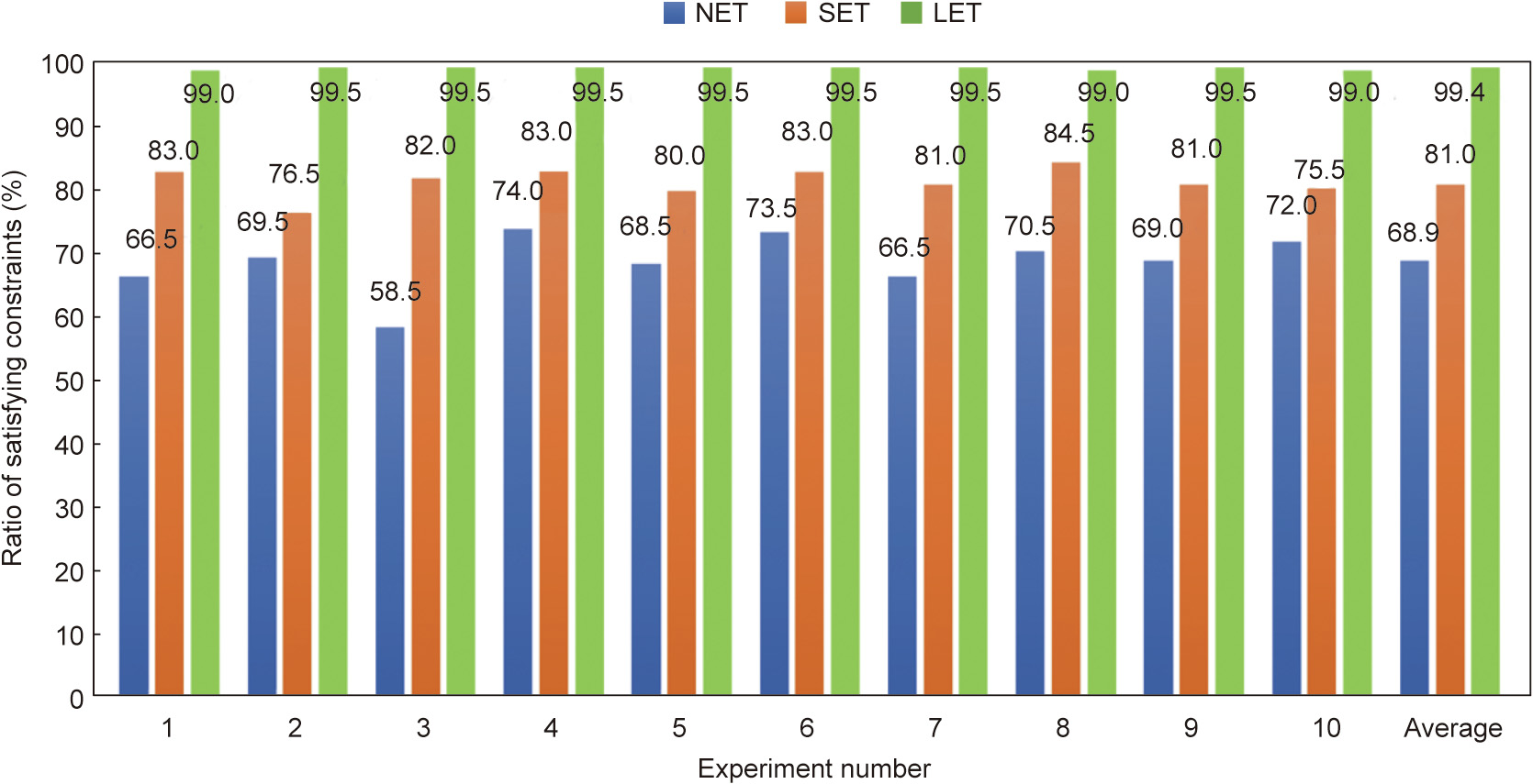
Fig. 6. Constraint satisfaction rate of random plans in the complex network.
《Fig. 7》

Fig. 7. Minimum total communication time pertaining to the random solution and algorithm solution in the complex network.
Fig. 6 indicates that when the time constraint is appropriately relaxed, the probability of the random plan meeting the time constraint significantly increases, and as the process execution time increases, the average probability of the random plan meeting the time constraint gradually increases. When the process execution time is considerably higher than the data transmission time in the network, the constraint satisfaction rate is close to 100%.
According to Fig. 7, although the satisfaction rate of the random plan meeting the time constraint is high, the total communication time of the solution obtained using the algorithm is much less than that of the ‘‘optimal” plan obtained using the random method. However, compared with the case of the simple network, the proposed algorithms in the complex network cannot easily converge to the theoretically optimal solution. As the process execution time increases, the communication time of the convergence solution tends to gradually stabilize at the minimum value.
《6.3. Algorithm convergence rate analysis》
6.3. Algorithm convergence rate analysis
The convergence rate of the algorithm for data networks with different levels of complexities and different process execution times is evaluated.
In the GA, the convergence rate for each generation update is

where Te_mink represents the minimum task completion time according to individuals (i.e., the manufacturing task allocation plans) in the kth generation. According to Eq. (17), two sets of experimental data for the convergence rate are randomly selected from the six groups of experimental data, and the convergence rate curve is shown in Fig. 8.
Fig. 8 shows that as the process execution time increases, the number of effective generations (the convergence rate of generations after this range is zero) gradually decreases. In the NET, SET, and LET scenarios, the number of effective generations is 100, 70, and 20, respectively. Therefore, as the process execution time increases, the number of population generations required by the algorithm to converge and amount of required calculation gradually decrease.
《Fig. 8》
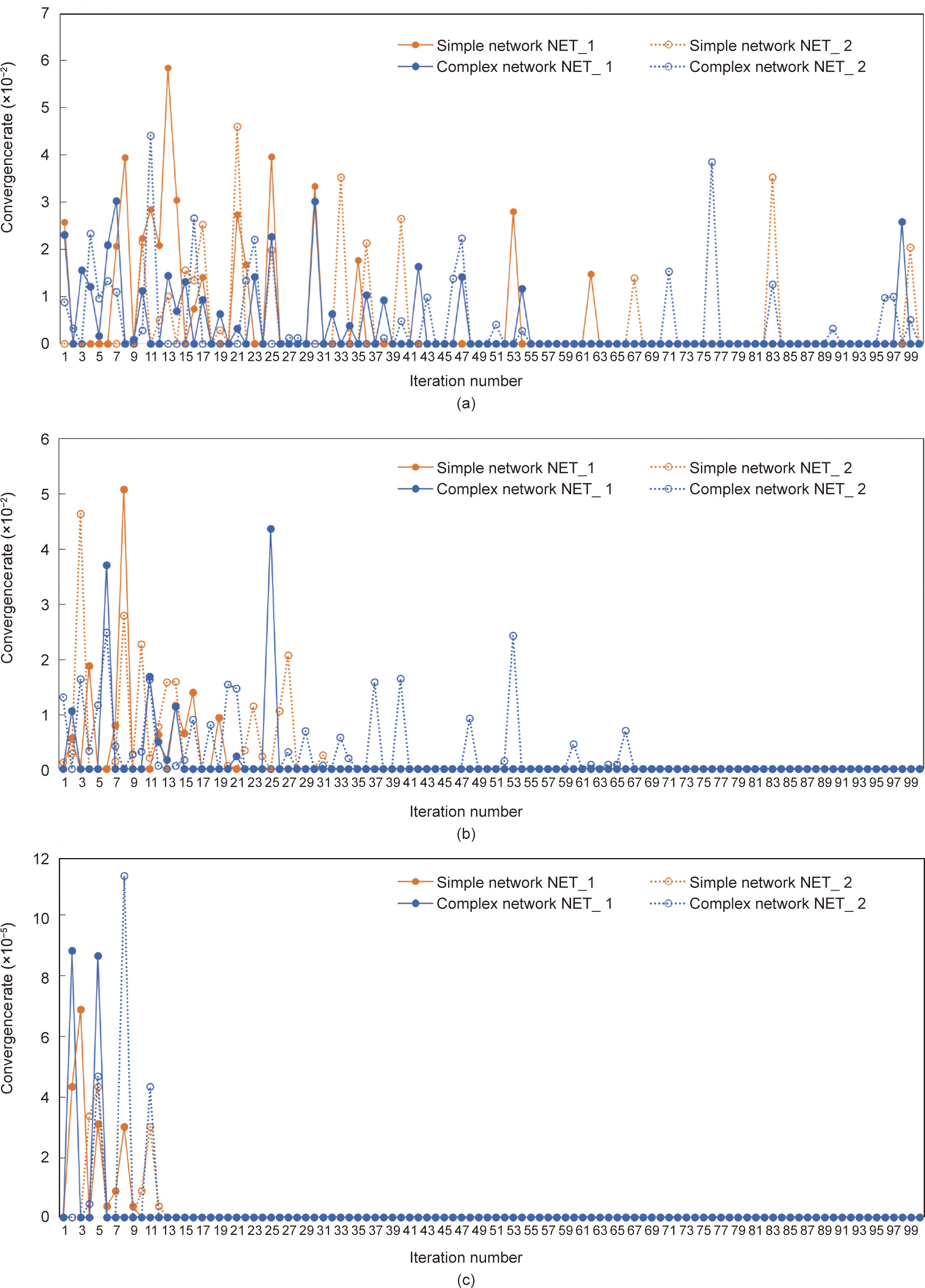
Fig. 8. Convergence rate curves under different process execution times. (a) NET scenario; (b) SET scenario; (c) LET scenario.
《7. Conclusions》
7. Conclusions
A new SDN-based CMfg model named SDCM is proposed. The SDCM adopts and extends CMfg with SDN and edge computing to make resources programmable. Moreover, the framework ensures fast reconfiguration, operation, and evolution of the manufacturing system to ensure that the system can promptly respond to external and internal changes. To reduce the network congestion and data transmission latency introduced by the large amount of data generated in SDCM, this paper builds a timesensitive data traffic scheduling model considering subtask allocation and data transmission path selection. Subsequently, the GA, Dijkstra’s algorithm, and a queuing algorithm are applied to solve the optimization problem to assign process execution units for the manufacturing tasks and meet the time constraint for the tasks. Experimental results show that both the model and algorithms can satisfactorily meet the constraint conditions and reduce the total communication time.
Future work can be focused on two aspects. First, we aim to improve the proposed path-planning algorithm for the optimization problem, perform additional comparisons with other algorithms, and conduct experiments under real industrial settings. Second, the security, data privacy, business priorities, and profit distribution, among other factors, must be considered to ensure that enterprises or owners are willing to provide the control logic of manufacturing resources. For enterprises or owners in a conglomerate, technologies or approaches to integrate and operate manufacturing resources safely or reasonably in a unified way may be established if the management is unopposed. Cases involving multiple stakeholders are considerably more complex. Therefore, we will continue to explore the issues associated with security, privacy, and business aspects.
《Acknowledgments》
Acknowledgments
The research is supported by the National Key Research and Development Program of China (2021YFB1715700), the National Natural Science Foundation of China (62103046), the Beijing Institute of Technology Research Fund Program for Young Scholars, the Chinese Academy of Sciences and University of Chinese Academy of Sciences for funding the research (Y92902MED2, E1E90808, and E0E90804), and the Fundamental Research Funds for the Central Universities (E1E40805).
《Compliance with ethics guidelines》
Compliance with ethics guidelines
Chen Yang, Fangyin Liao, Shulin Lan, Lihui Wang, Weiming Shen, and George Q. Huang declare that they have no conflicts of interest or financial conflicts to disclose.
《Appendix A. Supplementary data》
Appendix A. Supplementary data
Supplementary data to this article can be found online at https://doi.org/10.1016/j.eng.2021.08.022.


 京公网安备 11010502051620号


