

《1. Introduction》
1. Introduction
The additive manufacturing (AM) process aims at additively building three-dimensional (3D) objects from a 3D geometric definition in a classic layer-by-layer manner. Due to its unique layered forming principle, complex 3D physical models can be formed via the stacking of simple two-dimensional (2D) slices. With the rapid development of AM techniques and the emergence of related innovative materials, printing performance in terms of printing speed, accuracy, material consumption, cost, and postprocessing has continuously improved [1]. Among the numerous research efforts in this research field, designing lightweight structures with topology optimization or lattice filling strategies is quite popular due to tremendous application needs [2,3]. In addition, some other special structures—such as shell structures and hollow structures—are also used in a large spectrum of application domains [4]. Structural hollowing is an excellent way to save material, and less material means an apparent reduction in the 3D printing time and price. Simultaneously, the hollow geometry can generate new space in the original solid structure, providing the possibility to embed other parts. Current potential applications include wearable devices, internal sensor integration, and design based on weight minimization. As described in the literature, hollow structures were initially built from two main fabrication techniques: engraving and sculpting implemented by numerical control milling and turning [5]. Both techniques consist of removing excess parts from a solid surface to create a new shape, which is the representative process of subtractive manufacturing and is widely used in furniture design and decorations. In addition, a subtractive 3D printing technique called femtosecond laser-induced chemical etching was used to realize the production of geometrically complex 3D objects [6]. However, due to the tool accessibility problem, complex hollow and hull structures are difficult to machine. Moreover, the number of processing operations with related fixtures or masks, volume of sacrificial materials, and processing time increase substantially as the complexity increases [7].
Compared with traditional subtractive and formative manufacturing processes, AM brings more design freedom for hollow structures. Generally, some AM processes, such as fused filament fabrication (FFF) and stereolithography (SLA), need to use support/scaffold structures during material layer stacking. For relatively simple geometric models, existing printing preparation software tools are available to generate the support structure. However, for complex models with special requirements, the design of support structures is still challenging. Researchers have developed facilitators such as QuickCast style [8] and used various efficient support structures [9], such as scaffolding structures [10,11], tree structures [12], honeycomb structures [13], skin– frame structures [14], and medial axis tree structures [15], to save material and improve strength for internal or external support. Other researchers have proposed methods to distribute selfreconfiguration by using a deterministic autonomous scaffolding structure. For example, a 3D object was built using small flat elements that self-assemble to make a given shape [16]. However, even though sophisticated support structures can be designed and printed, the removal of the support structure and repair of the contact area in the postprocessing stage are still costly and challenging. There have been many efforts made on the material and process side to solve the problem. Carbon’s Digital Light SynthesisTM technology helped Adidas create a monolithic midsole with Futurecraft 4D [17]. The final midsole material is made out of a blend of ultraviolet (UV) curable resin and polyurethane. It is a stiff elastomer that can be printed in a lattice structure to create a highperformance midsole. Polymaker® produced a material called PolySupportTM specifically for printing support structures. This material is sufficiently adhesive and weak enough to be easily peeled off by hand after printing is complete. MakerBot® also has a dissolvable support material. In addition, cellulose nanocrystal gels [18] and biopolymer hydrogels [19] can be used as 3D printing support materials because of their sustainability, reproducibility, and potential recyclability. Although these gel scaffold materials exhibit outstanding biocompatibility and biodegradability and can even be used for medical applications, their disadvantages of easy shrinkage, brittleness, and poor mechanical properties require the adoption of crosslinking technology to improve their performance, which brings more complexity [20].
Other AM processes can avoid the presence of supports, such as multiphoton stereo lithography [21], suspended layer additive manufacturing (SLAM) [19], tomographic AM [22], and volumetric polymerization [23,24]. Digital light processing 3D printing (DLP) can exploit the photopolymerization-induced hybrid phaseseparating resins to create glass parts with complex shapes and multiscale porosity and density [25]. Hence, it is unnecessary to additionally design the support structure, and prototypes and components with complicated shapes can be directly produced without support. Nevertheless, it is not directly possible to create a fully closed but hollow volume, as the photoreactive resin present cannot be easily removed; for components with closed cavities, these efforts may still have a problem. Even with the selective laser sintering (SLS) process, the unsintered powder can provide sufficient support [26], but unused raw materials are left in the closed cavity after printing, with no removal solution. In the context of closed hollow structures, the aforementioned difficulties are reinforced. Fig. 1 shows an illustrative case of a hollow cube printed without a support strategy to highlight manufacturing difficulties and then surface quality issues. Recently, some researchers have proposed novel methods to minimize the support structure and even achieve support-free fabrication. For example, Wei et al. [27] used a skeleton-based algorithm to partition the shell model into support-free parts. Xie and Chen [28] designed unsupported voxels to carve internal voids. In these ways, an object can be directly manufactured without using any internal void support material. Dai et al. [29] implemented two continuous decompositions from volume to surface and then to curve, followed by multiaxis 3D printing tool path planning to reduce the support structure. However, these methods require many calculations in the model design process and high performance of the printer device. More importantly, although these methods meet the requirements of being lightweight and material compatible, they require much more computation time, and the final closed cavity structure cannot achieve functional part implementation. Therefore, finding a design and fabrication strategy to meet multiple objectives seems to be an original alternative to develop support-free hollow structures.
《Fig. 1》

Fig. 1. Example of FFF difficulties related to hollow 3D structure printing without a support or infill strategy.
Over the last decade, four-dimensional (4D) printing—combining AM techniques and stimulus–responsive materials—has emerged, giving a temporal dimension to 3D printed objects [30,31]. 4D printing is a process through which a 3D printed object transforms itself into another structure over the influence of external energy input such as temperature, light, or other environmental stimuli [26]. Compared with the existing 3D printing technology, 4D printing does have some limitations and needs more design and manufacturing steps. Some of the major challenges include the lack of multimaterial printers and smart materials, slow printing times, and limited studies on the long-term reliability of printed objects [30]. Specifically, 3D printing materials are rich in types and have different properties, but programmable and advanced materials suitable for 4D printing are still limited. It is difficult to meet the requirements of deformation and structural strength at the same time. In addition, for the choice of machines, 4D printing is often restricted by the types of multimaterial printers. Although prior to widespread adoption, 4D printing still needs to overcome some technical hurdles, it is undeniable that 4D printing is a promising technology [31]. It combines technology and design characteristics to fabricate dynamic structures with adjustable/tunable shapes [32], properties, or functions [33]. This gives an opportunity to avoid printing complex 3D shapes directly and overcomes the aforementioned manufacturing barriers. With the growing interest in 4D printing, origami-based design has also attracted increasing attention from researchers due to its unique and exquisite shape transformation from 2D to 3D [34]. It provides, in some sense, a simple way to build 3D geometry from a sheet of paper without the use of any cuts. Therefore, complex models can be described by crease patterns on unfolded paper [34]. Origami has inspired the design of several domains; once coupled with 4D printing, it is possible to design active structures [35]. Many advanced studies are being performed on active materials to achieve the desired folding behavior, leading to many representative structure designs [36]. Therefore, the combination of 4D printing and origami-based design seems to be a promising way to address hollow structures’ manufacturing difficulties.
The development of active materials enables engineers to design self-folding structures when used in appropriate geometries. Researchers have proposed a modeling framework for simulating smart materials and conventional materials behaviors on a voxel basis, allowing for arranging materials in any distribution and rapidly evaluating their behavior [37,38]. In addition, Ge et al. [39,40] and Yuan et al. [41] extended the concept of selfassembling origami by using spatial variations in the material composites to control shape deformation in an origami structure, and an active origami pyramid was treated as a case study. Kwok et al. [42] optimized the origami design of freeform surfaces for 4D printing. Van Manen et al. [43] analyzed hanging flowers as a case to illustrate their preprogrammed approach to achieve folding. Jian et al. [44] proposed a method based on 4D printing and origami to design self-reconfigurable structures via environmental stimuli without altering substructures or components. Furthermore, in terms of 3D bioprinting, the self-assembly strategy uses cell spheres as bio-ink or building blocks in a scaffold-free manner to fuse into a specific geometry, such as bilayer structures [45], double-layer vessel tubes [46]. Although the original goal of these case studies was not to build hollow structures, the results have inspired the work of this paper.
The research conducted shows that it is possible to form complex 3D objects by stimulating smart materials embedded in 2D origami precursors. However, these proof-of-concepts are generally based on predefined patterns, and there is still no practical way to manufacture a given complex 3D support-free hollow structure. As a consequence, the main objective of the paper is to develop an original origami-based design approach for 4D printing of support-free 3D hollow structures. Such endeavors will assist designers in representing complex hollow structures in origamioriented definitions embedding transformation sequence logic and stimulus–responsive materials and considering AM capabilities. The paper structure is as follows: Section 2 introduces the proposed 3D–2D–3D approach with an illustration example; Section 3 provides case studies with detailed implementation information; finally, conclusions and plans for future work are given in Section 4.
《2. Origami-based ‘‘3D–2D–3D’’ design approach》
2. Origami-based ‘‘3D–2D–3D’’ design approach
《2.1. Overall description》
2.1. Overall description
As discussed in the previous sections, origami-inspired thinking for design and manufacturing is an attractive and long-term research domain. The objective here is to cover the design and manufacturing of origami-based structures from the embodiment design to the detailed design stages. More specifically, the proposed origami-based design approach promotes guidelines and mechanisms to deliver 4D printing friendly origami-based solutions to cover hollow structure design and fabrication in a straightforward manner.
In general, the whole procedure of the proposed approach can be described as a 3D–2D–3D digital–physical transition strategy, which is composed of three main steps: ① 3D shape decomposition; ② 2D origami precursor design; and ③ 4D printing. Here, the proposal is illustrated via a cube, as shown in Fig. 2. First, the 3D roughly defined hollow structure is decomposed into predefined 2D origami precursors as corresponding unfolded planar patterns. Then, smart materials are allocated to active 2D crease patterns to link origami blocks for a connected 2D layout ready for 3D printing. Finally, the smart material embedded into printed hinges can be stimulated—according to a defined folding sequence—to ensure the hollow structure’s self-folding, thereby obtaining a complete 3D object without the need for a support structure. To further achieve this design strategy, we propose an origami-based design for the 4D printing approach for these three parts, and the flowchart is shown in Fig. 3. The specific steps are described in detail.
《Fig. 2》

Fig. 2. Origami-based ‘‘3D–2D–3D” design strategy for 4D printing hollow structures.
《Fig. 3》

Fig. 3. Flowchart of the proposed origami-based design for the 4D printing approach to build 3D hollow structures.
《2.2. 3D shape decomposition》
2.2. 3D shape decomposition
As part of the embodiment design stage, the initial step consists of decomposing a rough 3D model of the hollow structure. For this purpose, there are currently many ways to fold a 2D pattern to obtain a corresponding 3D shape [46], such as tree methods [47], but there are few ways to decompose a 3D object into a corresponding 2D origami pattern. Surface development [48] is a layout of the entire surface of a 3D object on a plane surface, a term frequently used in sheet metal work. The details of unfolding or unrolling the original structure into a flat sheet are called a pattern. This is a common method for ‘‘3D–2D,” but the plane graphics obtained lose the original structure’s characteristics. This stage aims at extracting the features of prescribed target 3D shapes by generating 2D projections or nets.
2.2.1. Meshing the 3D model
Since not all target structures have precise edges to be considered mountains or valleys, structures with smooth surfaces need to be meshed first, thus giving a vision of the possible cutting lines. Although this meshing step can be easily implemented by existing computer-aided design (CAD) systems, it should be noted that this produces numerous extra line information, as shown in Fig. 4. To solve this problem, it is important to find feature and characteristic information during the folding transformation process to distinguish the intermediate folds and redundant lines. The feature and characteristic elements of origami include the crease pattern, vertex, degree of the vertex, and folded state [36]. The skeleton of the topology optimization result can be extracted to ensure shape preservation, and a filtering method can be used to ensure characteristic preservation [49]. According to this information, it is possible to build the corresponding 3D meshed structure by removing the irrelevant lines, leaving only the mountain-valley related lines that can reflect the characteristics of origami. A 3D mesh model called M can be defined as a graph G(M)=(V, E), where V is the set of vertices and E is the set of edges. As illustrated in Fig. 4, the feature elements are represented by straight blue lines. In the meshing step, if it is necessary to retain as much feature information of the original structure as possible, more mountain-valley lines are used to retain layout capability for more hinges in the subsequent steps. It is worth noting that when meshing some curved surfaces, some of the surface features are inevitably lost regardless of how the accuracy is increased.
《Fig. 4》

Fig. 4. Example of a rough 3D hollow structure with its related mesh representation composed of edges and surfaces and the selected feature elements for 3D shape decomposition.
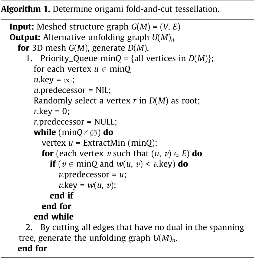
2.2.2. Determining origami fold-and-cut tessellation
Folding a 3D object requires knowing the original 2D plane and the necessary creases to obtain the desired form without ineffective overlap. In contrast, unfolding a 3D object requires cutting it along the edges or creases and then flattening it to a 2D plane [50]. Although cuts can be made anywhere on the 3D structure’s surface, it is necessary to retain each complete surface of the structure as much as possible.
To decompose the 3D mesh M to obtain its corresponding unfolding graph, the dual graph D(M)=(Vd, Ed) of the mesh M is introduced, where Vd is the set of vertices and Ed is the set of edges of the dual graph. The latter is used with Prim’s algorithm [50] to find the minimum spanning tree. It is worth noting that without considering the subsequent folding sequence, it is not possible to determine the weighted value distribution of the algorithm, so they are all set to the same value. This leads to different results, which can be represented as spanning path Pn, where n represents the nth spanning tree. Then, by cutting all edges that have no dual in the spanning tree of D(M), M can be unfolded into the alternative unfolding graph U(M)n = (Vu, Eu), where Vu = {vertices of U(M)}, Eu = {edges of U(M)} and the nth unfolding graph type corresponds to the nth spanning tree. The proposed fold-and-cut algorithm is described as Algorithm 1 below.
By applying such an algorithm, it is then possible to determine corresponding unfolding graphs to any 3D meshed structure. As an illustration case, Fig. 5 presents a meshed 3D cube, on which the proposed algorithm has been applied, therefore showing the dual graph and spanning tree with 3D representation to obtain the unfolding tree.
《Fig. 5》

Fig. 5. Example of a 3D mesh cube with its dual graph, one admissible spanning tree, and corresponding unfolding tree.
《2.3. 2D origami precursor design》
2.3. 2D origami precursor design
The objective of this part is to provide requirements and guidance to define the hinge geometry. Since the unfolding graphs are already available in the previous step, two parallel steps are processed to achieve the final goal. On the one hand, 2D thickness panels are defined from the unfolding tree to adapt to the specific AM process and technique. On the other hand, the best layout of the alternative unfolded trees and its folding sequence are computed. Such information is crucial for ensuring the hinge design step. The spanning tree only provides the topological layout of the 2D origami precursor. To achieve subsequent operations, all faces of the unfolding tree have to be transformed into panels with a specific defined thickness, leaving room for a later hinge design step.
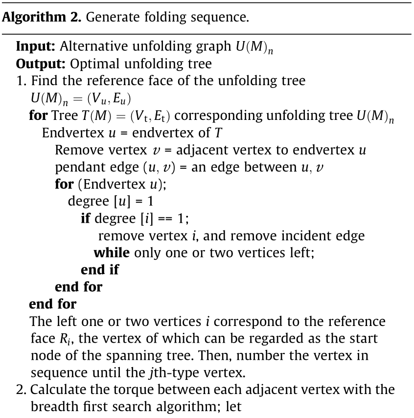
2.3.1. Determination of the folding sequence
By applying Prim’s algorithm on a given 3D mesh structure, several spanning trees and related unfolding trees can be obtained. To select one optimal topological layout for subsequent operations, for n possible unfolding trees, an algorithm is proposed to search the possible spanning trees and then compare them to select the best one according to specific criteria. Different folding paths require different actuations, leading to different results, such as the risk of collision. Without considering the collision for the simple case here, two objectives are defined: ① minimize the number of hinge types; and ② minimize the total sum of torques required to activate the hinges. The latter is important to reduce smart material consumption and/or stimulus intensity.
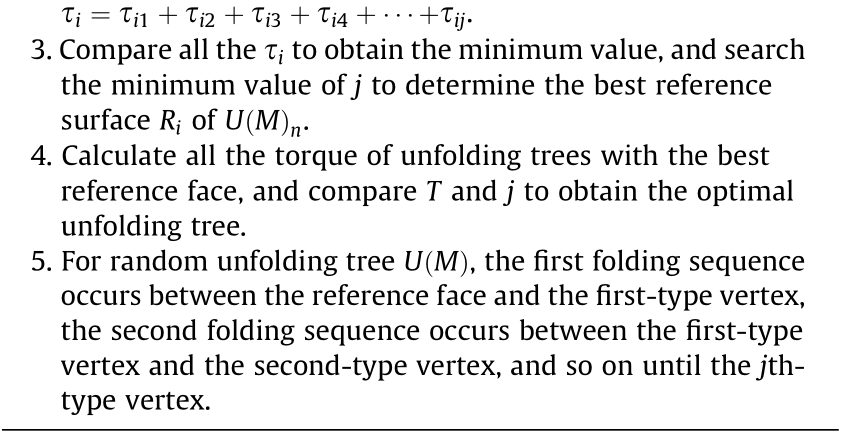
Before running the algorithm, the first step is identifying the base (reference) face, which refers to the fixed element of the folding structure during the actuation phase. The determination of the reference face should be done according to the aforementioned criteria. The further the reference face is from the unfolding tree’s center, the more torque is needed. For example, as shown in Fig. 6, if we consider the panel that goes to the top, one may want to fold it first so that the hinge at the bottom plane requires less torque. This means that the identification of the reference face is closely related to the search of the unfolding tree center. The center of the tree can be considered a vertex with minimal eccentricity. For an unfolding tree U(M)n = (Vu, Eu), the corresponding tree is T(M)=(Vt, Et), where Vt is the set of vertices and Et is the set of edges of the corresponding tree. To find the center or bicenters of this tree T(M), let us denote that an endvertex u in tree T(M) is a vertex of degree one and that a vertex v adjacent to an endvertex u is called a remote vertex. A pendant edge (u, v) is an edge between an endvertex u and a remote vertex v [50]. First, we remove all the vertices of degree 1 from the given tree and remove their incident edges. Then, we repeat the first step until either a single vertex or two vertices joined by an edge are left. If a single vertex i is left, then it is the center of the tree, and if two vertices joined by an edge are left, then they are the bicenters of the tree [51]. Alternative vertex of the bicenters can be regarded as the start vertex of the spanning tree. Here, this tree’s center can be represented by the reference face Ri of U(M)n, where i refers to the face number of the unfolding graph. The vertices on the face sharing the edges with the reference face of the unfolding tree are called firsttype vertices. The vertices on the face sharing the edges with the first-type vertices face called second-type vertices, and so on, until all the vertices on the faces of U(M)n are covered, and the vertices farthest from the starting vertex are called jth-type vertices. By using the vertex of the reference face Ri as the starting point, the folding sequence can be generated by the corresponding spanning tree.
《Fig. 6》
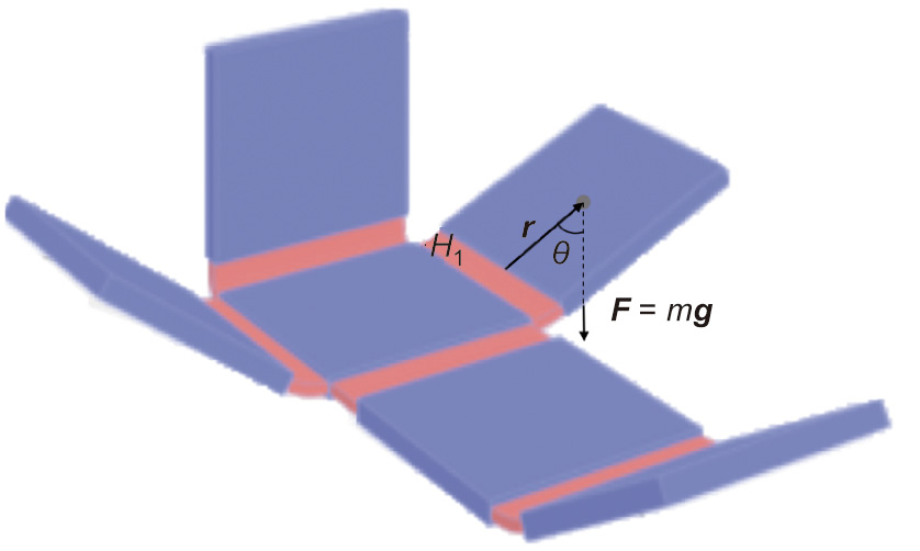
Fig. 6. Diagram of the relationship between force F, position vector relative to the fulcrum r, and angle between the position and force vectors θ for the hinge H1.
At this time, the folding paths for different reference faces Ri of the unfolding tree U(M)n have been determined. To select the best face for the 4D printing steps (i.e., stimulation and actuation steps), the torque required for each case needs to be calculated. Torque, referring to the ‘‘turning effect,” is the product of the magnitude of the force and the perpendicular distance of the line of action of force from the axis of rotation. Here, the torque τ of each hinge depends on the mass of the linked panels to overcome and the distance from the center of gravity to the hinge (Eq. (1)).

where r is the particle’s position vector relative to the fulcrum and F is the force acting on the particle. The magnitude τ of the torque is given by

where r represents the distance from the axis of rotation to the particle here is the distance from the center of gravity of each panel to the crease, F is the magnitude of the force applied (here, F = G = mg, where m is the mass of the panel, g is the local acceleration of free fall), and θ is the angle between the position and force vectors, as shown in Fig. 6. Assume that the change in θ can be ignored during the entire folding process, the torques of this case τ0 is defined as follows:

The sum of the required torque τi corresponding to each unfolding tree U(M)n with the reference face Ri is

where τij refers to the required torque at the jth crease of the unfolding tree U(M)n ,which corresponds to the jth-type vertices with the reference face Ri and where the total torque is positively related to the quality of the panel to be folded. Here, we propose a relationship between the total sum of the torques of the different reference faces and the number vertices.
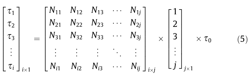
where i refers to the face number of the unfolding graph and τi refers to the torque of the reference face Ri. In addition, j refers to the farthest vertices number from the starting vertex on the reference face. Therefore, the jth types of vertices refer to j vertices to get from the starting vertex to this vertex and Nij refers to the total number of j types of nodes when taking i as the reference face.

After obtaining the minimum torque and type through the best reference face of each unfolding tree related to each generated spanning tree in the previous step, the objective is to compare admissible solutions by considering the two aforementioned criteria. For this purpose, a weighted equation is used to evaluate the optimal solution of the unfolded tree to obtain the minimum spanning tree. The optimal unfolding tree here is the one with the smallest torque τ and the smallest number of node types j. The proposed algorithm to achieve this goal is described as Algorithm 2 below.
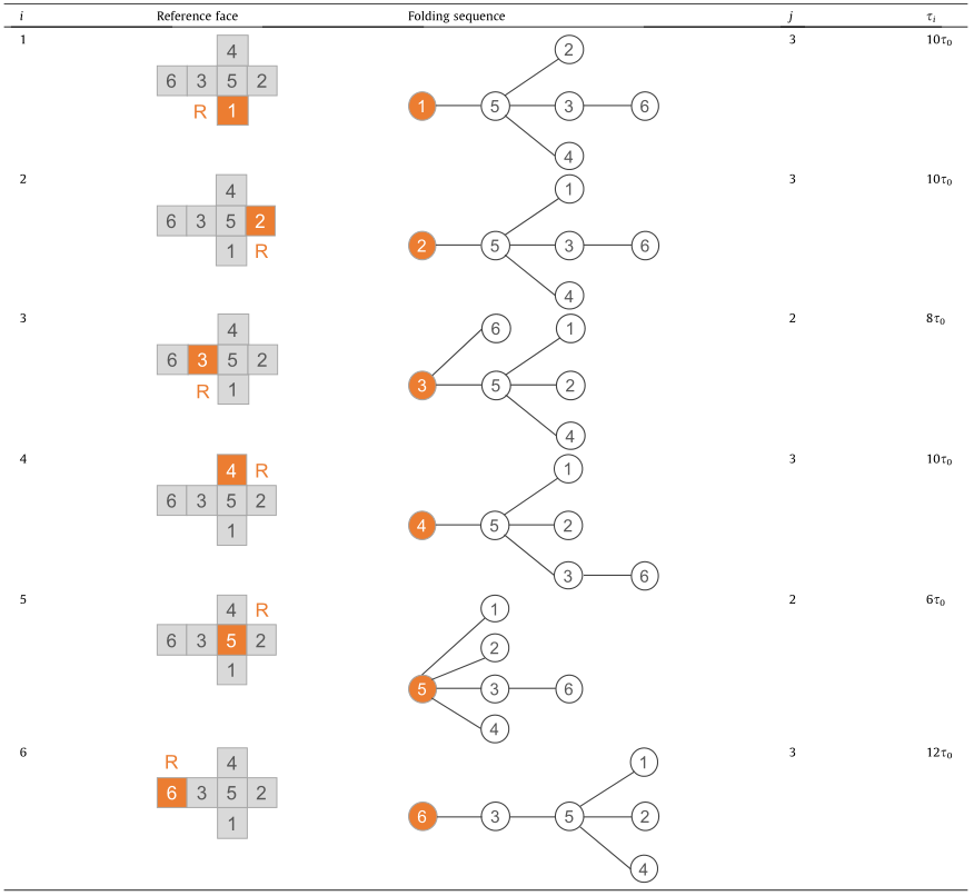
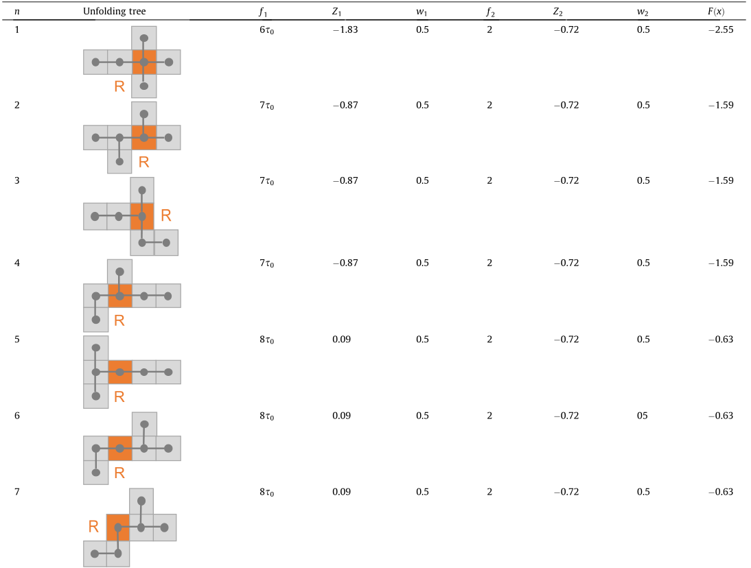
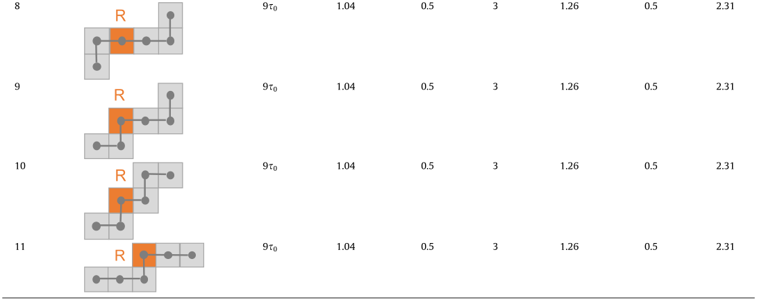
With this second algorithm, the optimal unfolding tree and its folding sequence can be set up. To illustrate its applicability, Table 1 presents, for a given unfolding tree of a cube, the required torques and the types of nodes are different according to the position of the reference face R. From this table, defining the fifth face as the reference seems to be the best choice. Then, the folding sequence can be generated by first folding the face where the first type of vertex is located and then folding the face where the second type of vertex is located at the same time. After selecting the optimal reference face for each unfolding tree U(M)n, the next step is to compare them to select the optimal unfolding tree, as shown in Table 2. Thus far, the two objective functions defined in the previous section can all obtain their specific values.
《Table 1》
Table 1 Torque and node types corresponding to different reference faces.
《Table 2》
Table 2 Torque and node types corresponding to different unfolding graphs.
The final optimal spanning tree can be determined by considering different requirements or objectives. Here, the two objective functions—denoted  and
and  as described in Eqs. (7) and (8)—aim to ① minimize the number of hinge types; and ② minimize the total sum of torques required for hinge actuation. To make optimal decisions in the presence of trade-offs between two or more conflicting objectives, such as involving these two objectives in a comprehensive indicator to determine the final spanning tree, a multiobjective optimization is introduced.
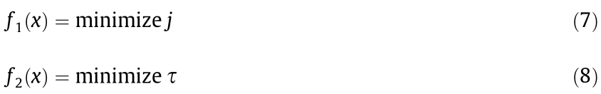
To transform a multiobjective optimization problem into a single objective, we can often use the weighted sum method [52]. The object function minimizing  is described below:
where x is the unfolding tree and , , and X is the feasible set of decision vectors. Since these two objective functions are nonhomogeneous, a normalization method is used to transform the dimensional quantity into a dimensionless quantity. If the population mean and population standard deviation are known, the raw score is converted into a standard score by

The raw score is converted into the standard score by

where μ is the mean of the population and σ is the standard deviation of the population.  and
and  have no physical dimension at this point. We scalarize a set of objectives into a single objective by adding each objective premultiplied by a user-supplied weight. Weight is a relative concept that represents the importance of the object being evaluated, and different weights can be quantitatively assigned to different objective functions. The weighted sum S is defined as follows:

where  is the weight function and
  = 1. In the cube case, since these two objective functions are equally important, the weights are equally distributed at 0.5 for each of them. If there are other factors and considerations, the weight function can be adjusted at any time. Then, Eq. (9) can be transformed into

The symbolic example in Table 1 shows the alternative sequences and their evaluation. For complex cases with more connected 2D panels, the number of alternative unfolding sequences may significantly increase due to the combination operation. Hence, screening methods to rank alternatives may not work for costly computation, but optimization tools, for example, combinatorial optimization algorithms, should be used.
2.3.2. Identifying active hinges
Once the optimal layout and the folding sequence are defined, hinges can be allocated to the creases of the 2D origami layout. Contrary to the active/passive hinge determination step proposed in Refs. [44,53], all hinges here are assumed to be active and composed of smart materials. To this end, the geometric design stage needs to meet two requirements: ① be able to deform under external stimuli to achieve folding; and ② be able to fold accordingly with the predefined folding sequence. The former involves the interaction mechanism of 4D printing and the specific hinge geometry. The latter involves the temporal responsivity of the hinges to be consistent with the folding.
The interaction mechanism needs to be determined so that the printed smart structure can respond to stimuli in an appropriate manner. As mentioned in the review section, various mechanisms have been developed to realize the 4D printing process, such as hydromechanics [33] and thermomechanics [40], and various smart structure geometries have been produced with shape memory materials, such as bilayer structures [45], sandwich structures, and fiber structures [54]. The complexity of design and manufacturing varies among these mechanisms and the corresponding active hinge geometry, and the specific solution can be selected based on the specific requirements. To ensure a folding sequence, two control mechanisms can be applied: ① different smart materials or materials with different responsivities; and/or ② different stimuli or different stimulus intensities.
2.3.3. Hinge geometry design
The hinge design is mainly based on the material composition and structure geometry, while the role of the hinge is mainly reflected in two aspects: achieving a specific folding angle and folding in a programmed way. Since the folding sequence of the cube case is already generated based on Table 1, to achieve the final structure, two folding operations are needed, and the corresponding hinges are noted as the first type hinges and the second type hinges. As illustrated in Fig. 7, both of these hinge types need to fulfil the 90° folding requirement; however, they need to have different temporal responses. This information can be defined as the basic requirements of selecting the interaction mechanism and designing the hinge geometry.
《Fig. 7》

Fig. 7. Specific hinge design based on the optimal unfolding tree.
To fulfil these requirements, there are many materials and structural options that can be chosen. To further determine the specific hinge design, other additional conditions can be used to make the right decisions. By still using the cube as an example, one may assume that there is no restriction on the selection of the materials and processes. Since temperature seems to be the easiest physical property to implement and control, this stimulus has been used as the triggering mechanism here. Based on the studies of Ge et al. [39,40] and Yuan et al. [41], printed active composites (PACs) consist of different digital materials, which have the shape memory effect and can be used to realize shape shifting behavior. This advanced study provides technical support for the proposed hinge design. In principle, the hinge geometry can be regarded as a fiber-reinforced structure, where the folding angle can be controlled through adjustment of the thermomechanical loading program and the printing parameters. The folding sequence can be controlled by varying the number of fibers of different hinges. Based on this information and the assumption of considering the same stimulus intensity, the specific geometry can be defined for each hinge. As shown in Fig. 7, the temporal delay of the green hinge actuation is based on fewer fibers than that of the red hinge actuation. There is no doubt that there are still many other methods to meet the basic requirements; for example, some two-way shape memory materials exhibit reversibility, which brings an innovative effect for geometry and stimulation design [55], and designers can adapt these methods according to their specific actual situation.
《2.4. 4D printing》
2.4. 4D printing
As mentioned beforehand, the specific hinge geometry design for 3D/4D printing strategy has been formulated to address hollow structure design and fabrication issues. After finishing the 2D origami precursor design process, a suitable 4D printing technology is the key to achieving the final structure fabrication. Furthermore, another way to realize sequence folding is by controlling the external stimulus, which also needs to be discussed. Therefore, the main goal of this step is to determine the final 4D printing solution, achieve the fabrication process through multimaterial printing, and then actuate the printed structure by external stimuli to obtain the final target hollow support-free structure.
2.4.1. Specific 3D/4D printing strategy definition and realization
A complete 3D/4D printing strategy includes specific geometry, material distribution, reaction mechanism, and AM technology. These factors are not entirely independent but affect each other. Therefore, a suitable AM method can be selected to match the designed hinge, the determined mechanism, and smart materials in the previous steps. Since PACs are built as fiber-reinforced structures, including the matrix as an elastomer and the fibers as a glassy polymer, the PolyJet technique can be selected for multimaterial polymer printing and parameter adjustment here.
As shown in Fig. 8(a), the hinge parts are fabricated with matrix and fibers. Each hinge has two layers of equal thickness; one is fiber reinforced, and the other is the pure matrix. Since the panels do not need to change the form during the folding process, they are fabricated in rigid materials. The materials related to the fiber, matrix, and rigid parts are digital material (FLX9860, also termed Gray 60), Agilus30Black, and VeroWhite, respectively. All materials are commercially available (Stratasys®, USA). The process planning setting of the whole structure is shown in Fig. 8(b). A corresponding multimaterial printer (Objet Connex 260, Stratasys®) is required to achieve structure fabrication, and the printed structure is shown in Fig. 8(c).
《Fig. 8》

Fig. 8. Hollow cube implementation with (a) hinge composition, (b) process planning setting, (c) the 2D printed origami precursor, and (d) the 3D structure once stimulated.
2.4.2. 3D printed structure actuation strategy
The last important step is to add external stimuli to achieve the final deformation according to the generated folding sequence. In the foregoing, it was discussed that the control of sequential folding can be achieved by designing different geometric structures for different hinges. In this case, the printed structure is deformed in response to the same external stimuli. After heating and stretching the printed structure, as shown in Fig. 8(c), biaxially, the hinge part is folded when the loads are released at low temperature, thus achieving the final hollow structure, as shown in Fig. 8(d). Because the fiber numbers of the two types of hinges are different, in the same external environment, the required folding times are different.
Another situation worth discussing here is to achieve sequential folding by controlling stimuli. When all the hinges have the same geometry, different stimuli intensities can be applied to the hinges at different positions to achieve a temporally programmed response, or external stimuli can be applied at different times for the hinges at different positions. Each method has its advantages and disadvantages, and designers can design and select them according to the specific situation.
Thus far, after the three main steps of 3D shape decomposition, 2D origami precursor design, and 4D printing, the designer can obtain the corresponding ‘‘self-folded hollow structure” as the output according to the initial input ‘‘rough 3D hollow structure.” Through this approach, the final hollow structure successfully avoids printing the support structure, but it is undeniable that the final result (Fig. 8(d)) does not remarkably resemble the original design (Fig. 4). The reason is that the material properties may not be accurately modeled during the design. Moreover, warping during printing is not taken into account. The final structure is transformed by printing the unfolded structure and then stimulating the active hinge to fold it automatically. The final structure is formed by printing the unfolded structure and then stimulating the active hinge to realize the folding automatically. In this process, by introducing the hinge at the crease location, because of the uncertainties and variations in the mechanical properties of 3D printed materials, it is inevitable that the original structure becomes distorted in size and form, and the material model is not accurate enough. Therefore, the limitations of this method should be clarified before the process of applying this method.
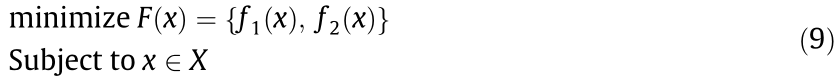
We compared the proposed origami-based 4D printing method with other support-free methods mentioned in the previous review, as shown in Table 3 [19,27–29]. According to whether 3D hollow structures are completely hollow, we can divide these structures into ‘‘shell-only hollow structures” and ‘‘shell–core hollow structures.” It can be seen from the table that our method is more suitable for the former. Compared with other existing methods, although the hollow structure obtained by 4D printing cannot obtain relatively high accuracy and resolution, it is not a completely closed structure produced by one-time fabrication, which provides opportunities for the subsequent embedding of other functional parts. It is also relatively suitable for a wider range of machines and materials. It is not very applicable to the situation where the target hollow structure needs to be entirely consistent with the original structure and the final structure needs to be completely closed. Engineers can choose a more suitable method according to the goals and characteristics of different hollow structures.
《Table 3》
Table 3 Comparison of different support-free methods.
《3. Case study》
3. Case study
With the rapid growth of interest in microrobotics and wearable electronics, smart-structure embedded sensors and other electronic components have attracted significant attention. Many research questions have also emerged, such as how to embed electronic components in a hollow structure without damaging the surface. The proposed strategy can solve this problem. To illustrate the generalization of the proposed approach to more general structures, an application to Platonic solids is proposed. Here, tetrahedrons and octahedrons are identified as the target structures, and light-emitting diode (LED) lights are identified as the electronic components to be embedded.
As shown in Fig. 9, in the 3D decomposition step, regarding the geometric characteristics of the Platonic solids, the edges can be directly considered as the ‘‘mountain fold” in the 2D origami precursor, and one of them can be used as the cutting line. For the selection of specific unfolding trees, the 2D planes with axial symmetry and center symmetry for these two special structures are determined. In the 2D origami precursor design step, a specific thickness based on the previously determined unfolding tree is specified to minimize the total folding number. Then, since there is no requirement such as ‘‘minimizing the consumption of smart materials” here, the determination of the folding sequence needs only to consider embedding LED lights. To simplify the overall design, the middle hinge is identified as the second-type hinge, and all the other hinges are identified as the first-type hinge, which folds at the same time. The LED lights are embedded during the time difference between the two types of hinge folding. To control the folding time more accurately, all the hinges are designed in the same geometry, and the deformation is controlled by the application time of the stimulation. Since the proposed method has no restrictions on the AM process, to show more possibilities, in the 4D printing step, we selected thermomechanics as the mechanism and polylactic acid (PLA) as the printed material; all the hinges were designed in the same bilayer structure [43]. 3D printers (Ultimaker® 2+, Ultimaker®, Netherlands) configured with FFF and PLA filaments (Ultimaker®, filament diameter = 2.85 mm, Tg = 60–65 °C, Tg represents the glass transition temperature of the materials) were used for fabrication of all design solutions presented in this work. After the 2D structure is printed, thermal stimulation is first applied to the first type of hinge. After these hinges are folded, LED lights are placed in this structure that is not completely closed, and thermal stimulation is then applied to the second type of hinge to fully fold the central hinge until the overall structure is closed. Upon going through these steps, internal hollow tetrahedron- and octahedron-embedded LED lights are successfully obtained, as shown in Fig. 10.
《Fig. 9》

Fig. 9. Fabrication of the two hollow platonic solids. (a) Tetrahedron; (b) octahedron.
《Fig. 10》

Fig. 10. Process of embedding LED lights in hollow octahedron: (a) printed structure with the same hinges; (b) structure with the first stimulation and embedded LED lights; and (c) structure with the second stimulation.
《4. Conclusions and future work》
4. Conclusions and future work
This study has demonstrated a design and fabrication method for hollow structures using 4D printing and origami-based design. We first introduced this ‘‘3D–2D–3D” strategy and then elaborated three steps, including 3D decomposition, 2D origami precursor design, and 4D printing. Finally, a representative case study was used to prove the feasibility of this method and provide more possibilities for future study of electronic components embedded in hollow structures. We elaborated all the steps in detail with the cube case; thus, designers can adjust, add, or delete one or more steps according to their specific design requirements. Decomposing a nonplanar surface into planar elements connected to each other by structures made of intelligent materials can easily allow the realization of hollow objects of complex shapes. This proposed approach provides a guide for fabricating hollow structures and other similar complex structures that are support-free in printing. Using the ‘‘folding–unfolding” structure transformation of origami, the required 2D plane is easier to manufacture and easier to stack for storage, transportation and remote deployment, while the 2D structure is more compatible with other fabrication processes. This method gives the development of new design directions to manufacture hollow structures and integrated products and the implementation of novel concepts of 4D printing and origami technology.
However, the proposed method still has some shortcomings and limitations. First, the hollow structure obtained by this method cannot be completely closed. Second, 3D mesh decomposition significantly changes the design in terms of structure and materials. The shape design of the hollow structure undergoes changes in size and form with the introduction of hinges. There are quite substantial differences in form and function, and these differences may significantly impact the original design intent of the hollow structure. Since this method achieves structural changes through hinges, some of the original structural features are lost during the design process. Finally, this method provides only a guideline for the design process; the specific structure accuracy is highly dependent on the performance characteristics of smart materials and interaction mechanisms [55]. The optimization of the final structure significantly depends on the development of 4D printing research, and there are specific requirements for the designer’s material knowledge reserve. This method is not very suitable for situations requiring precision manufacturing.
For future arrangements, we plan to design the hinges in detail with the support of 4D printing knowledge [56] and optimize the layout of different functional parts—through a dedicated application within a CAD environment—to achieve more precise control of the folding for a more complete structure. In addition, for complex cases with more connected 2D panels, whether the two panels collide during folding needs to be considered as a new indicator to determine the layout. In addition, the number of alternative unfolding sequences may significantly increase due to the combination operation. Hence, the screening method to rank alternatives may not work for costly computation, so some optimization tools, for example, combinatorial optimization algorithms [52], should be used for other more complicated cases.
《Acknowledgments》
Acknowledgments
This research activity is part of a much larger project in the field of design for 4D printing. The authors would like to thank the Ministère de l’Enseignement Supérieur et de la Recherche, the French ‘Investissements d’Avenir’ program, project ISITE-BFC (contract ANR-15-IDEX-0003) and China Scholarship Council as the main financial supports of this research program.
《Compliance with ethics guidelines》
Compliance with ethics guidelines
Bingcong Jian, Frédéric Demoly, Yicha Zhang, H. Jerry Qi, JeanClaude André, and Samuel Gomes declare that they have no conflict of interest or financial conflicts to disclose.


 京公网安备 11010502051620号


