

《1. Introduction》
1. Introduction
As a synthesis of mechanism and structure, deployable structures are the optimal solution for addressing engineering problems in the field of aerospace, which is the frontier field of engineering research. Deployable structures are an extension of a basic unit composed of rods, cables, and membranes, and are overconstrained systems with simple configuration and good stiffness. In addition, they are sensitive to dimensional and shape errors [1– 5]. Space-deployable structures exhibit the following main characteristics: ① Diversification of structural units and combination rules makes the geometric design of deployable structures flexible; ② their stiffness can be modified by adjusting their internal pretension with cables or membranes; ③ their good scalability facilitates their scaling down for prototype development, modeling simulation, and validation, or scaling up to meet potential mission requirements; and ④ new deployable structures can be designed based on bionic principles.
Deployable space structure technology is a potential approach to solve the contradiction between the requirements of largescale spacecraft structures and the envelope limitation of a rocket launch. These structures are first mounted in the carrier in a folded state with a small volume and then deployed into a working state by ground command. Since the 1990s, supported by major national projects, such as manned spaceflights, lunar exploration, Mars exploration, large space telescopes, and high-resolution earth observations, China’s deployable space structure technology has made considerable progress. Space-deployable structures have been successfully applied in many space engineering projects, such as large-diameter satellite antennas [6–13], the mast in a space station [14–19], solar arrays of satellite communication systems [20–24], rigid and flexible solar arrays [25–32], and Mars/lunar rovers [33–39]. The size of China’s on-orbit space-deployable structures has reached 20–30 m, and their position and shape accuracies are less than the submillimeter order. Leng’s group [40] has made solid progress in releasing mechanisms based on shape-memory polymer composites (SMPCs). In 2020, structures positioned in a curved shape were designed to deploy the CubeSat’s solar arrays. In addition, Leng’s group [41] achieved further optimization to improve the deployment synchronization. Thus, large-scale, lightweight, and high-precision spacedeployable structures have become a hot research topic in the field of aerospace science and technology in China. This paper presents the typical applications, research progress, and development trends of space-deployable structures in China.
With the development of deployable mechanisms, many design theories have emerged to study their configuration, kinematics, and dynamics. For example, graph theory [42], a topology method widely utilized in the configuration design of deployable mechanisms, considerably enriches the mechanism configuration. For a deployable mechanism with multiple loops and over-constraints, screw theory can easily analyze the kinematics by using the Denavit–Hartenberg (D–H) method [43], because it can rapidly determine the position of the axis in the mechanism. In addition, based on screw theory, kinematic chains can be matched to generate new configurations [44], and the singularity of motion can be easily analyzed [45]. Recently, origami [46] has been used to interpret the design of the rod mechanism from a novel sight, enriching the design methods of the expandable mechanism.
《2. Research progress and applications》
2. Research progress and applications
Through years of research and development, space-deployable structures in China have realized a leap forward in development for on-orbit deployment from a one-dimensional (1D) deployable arm and two-dimensional (2D) plane array to three-dimensional (3D) structures. Typical deployable structures include large space mesh antennas, space manipulators, space solar arrays, and deployable structures and mechanisms used in the field of deepspace exploration (Table 1).
《Table 1》
Table 1 Different types of space-deployable structures.

SAR: synthetic aperture radar; BD: Beidou; CE: Chang’e; HJ: Huanjing; DFH: Dongfanghong.
《2.1. Large space mesh antennas》
2.1. Large space mesh antennas
With their large aperture, high storage ratio, and light weight, space-deployable mesh antennas present natural advantages to fit the limitations of the whole satellite weight and the rocket fairing size. The large aperture can provide high gain, while the high storage ratio, light weight, and deployability can overcome the limitations of the weight and size envelope in the launch stage. After years of efforts and development, many large space mesh antennas have been successfully developed in China and applied to Beidou (BD)-3 navigation, lunar exploration, relay communications, and other fields. Typical applications include the framed deployable antenna of the BD-3 satellite, the umbrella deployable antenna of the Chang’e (CE)-4 satellite, and the synthetic aperture radar (SAR) antenna of the Huanjing (HJ)-1C satellite.
The BD-3 satellite is a global coverage positioning and navigation system that was independently built by China [47]. Fig. 1 shows the two framed deployable antennas of the BD-3 geosynchronous earth orbit (GEO) satellite. The antennas are mainly composed of a truss antenna reflector, a multistage deployable device, a reflector installation pedestal, a scanning mechanism, and feed components. The antenna reflector adopts a tetrahedron frame unit. Each unit comprises three web members, three folding rods, a faceplate, and torsional spring driving components. The diameter of the antenna reflector is 5 m and the storage ratio is 1:10. The BD-3 satellite realizes the on-orbit application of an offset-fed framed deployable antenna, using many key technologies, such as a stable and reliable deployment of the antenna reflector and high-precision scanning control. These breakthrough key technologies provide vital support to make the BD satellite a world-class navigation system and to open up an independent innovation roadmap for the subsequent construction of the BD system.
《Fig. 1》

Fig. 1. Framed developable antennas of the BD-3 GEO satellite. GEO: geosynchronous earth orbit.
The CE-4 relay satellite runs around the Lagrange-point (L2) on the halo orbit of the Moon, and its longest communication distance with the CE-4 lander and rover is approximately 7.9 × 10⁷ m (Fig. 2) [48]. Limited by the transmission power and antenna size of the lander and rover, the signal level received by the relay satellite is usually weak. Therefore, higher requirements in terms of the aperture and gain of the relay communication antenna have been proposed to ensure the successful establishment and performance of the relay communication link. Furthermore, the antenna of the CE-4 relay satellite adopts a parabolic umbrella scheme, as shown in Fig. 3. The antenna diameter is 4.2 m and the gain is 45 dB, which can effectively meet the requirements of long-distance communication.
《Fig. 2》
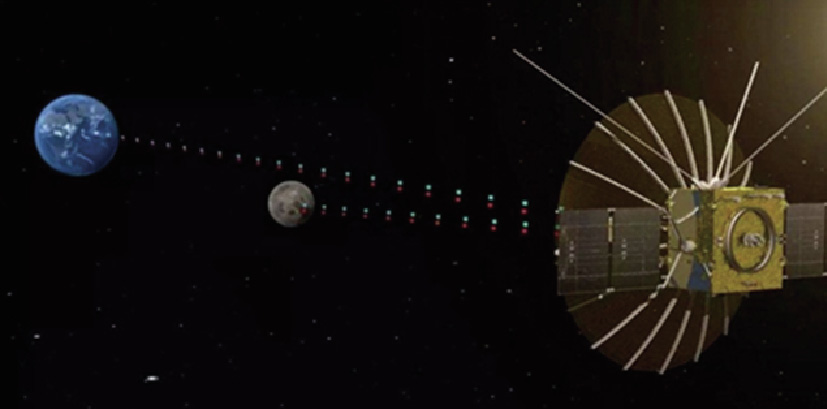
Fig. 2. Mission map of the CE-4 relay satellite.
《Fig. 3》
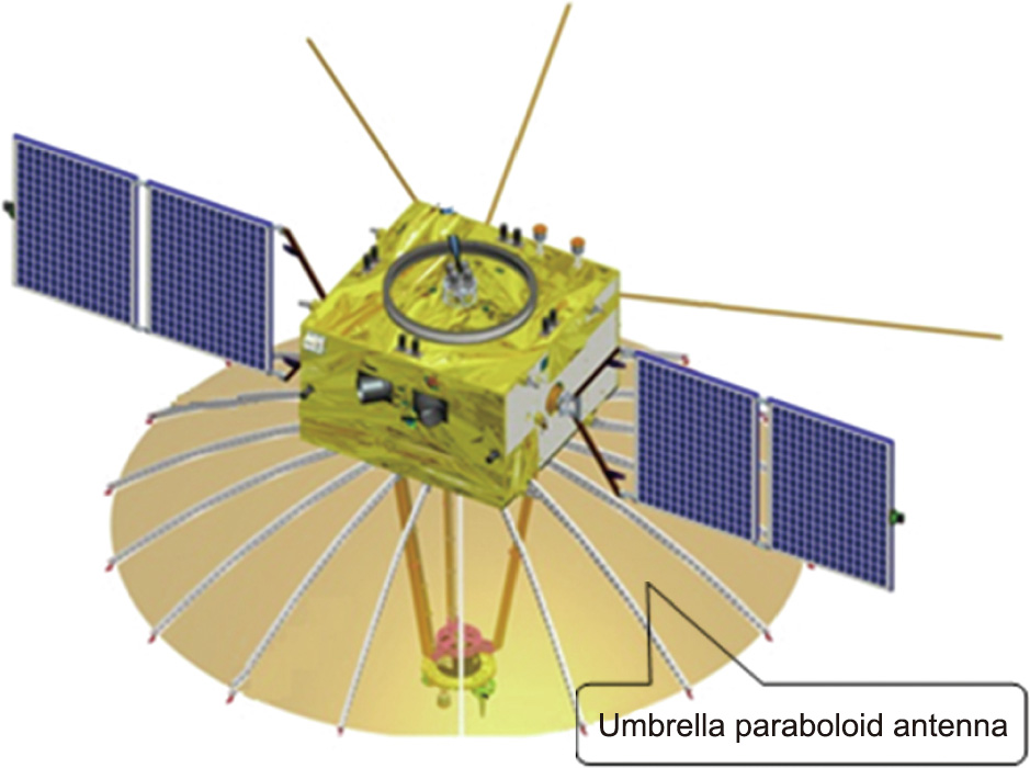
Fig. 3. Umbrella paraboloid antenna.
The HJ-1C satellite is China’s radar satellite for environment and disaster monitoring, and is capable of all-weather and all-day observations. To address the issue of whole-day observations, the SAR antenna of the HJ-1C satellite adopts the technical solution of a deployable parabolic frame antenna and a multi-beam feed [49]. Compared with a microstrip planar array and waveguide slot array antennas, a framed deployable antenna has the advantages of small folding size, light weight, and easy realization of multi-beam array and multiple polarizations. The applied framed deployable antenna mainly comprises a reflector, feed, and deployed components. The deployed components include a deployable arm, the rotating mechanism, the deployed feed mechanism, the fourth support structure, and pressure-relief devices. The on-orbit deployment sequence of the whole antenna is as follows: fourth support bar, feed mechanism, antenna deployment arm, and frame antenna reflector (Fig. 4). The frame antenna reflector is composed of numerous units with a tetrahedral structure, and each unit comprises three web members, three folded rods, and torsion spring driving components. The deployment of the frame antenna relies on its spring driving components; the working principle is shown in Fig. 5.
《Fig. 4》

Fig. 4. On-orbit deployment process of the SAR antenna.
《Fig. 5》

Fig. 5. Structural unit of the SAR antenna. A–O: kinematic mechanism nodes of structural unit.
《2.2. Space solar arrays》
2.2. Space solar arrays
In the 1980s, China began to develop deployable solar arrays. At present, the number of successfully run on-orbit solar arrays has exceeded 500. According to the product’s structural features, China’s deployable solar arrays are mainly divided into rigid, semi-rigid, and flexible solar arrays.
China’s Dongfanghong (DFH)-4 platform is a typical rigid solar array—that is, it is a 1D secondary-deployment rigid solar array composed of a connecting frame, panels, and a set of mechanisms. The mechanisms include the primary and secondary hold-down and release mechanism and the primary and secondary deployment locking mechanism, as shown in Fig. 6. The secondary deployment of the solar array requires a unique deployment mechanism to realize the function of the secondary deployment of the outermost panel, especially for the functions of deployment, locking, unlocking, redeployment, and relocking. After the satellite reaches the transfer orbit, the primary compression device is unlocked and the outer panel is deployed to 90°. When the satellite enters quasi-synchronous orbit, the secondary clamping device is unlocked and the connecting frame and other solar panels are expanded to 90°. The locking hinge of the outer panel is automatically unlocked and is then synchronously deployed and locked with the connecting frame and other panels, as shown in Fig. 7. Table 2 compares the performance of rigid solar arrays developed in China with that of another solar array developed in Europe.
《Fig. 6》

Fig. 6. Working configuration of the solar array of the DFH-4 platform. (a) Configuration of DFH-4 platform; (b) mechanisms of rigid solar array.
《Fig. 7》
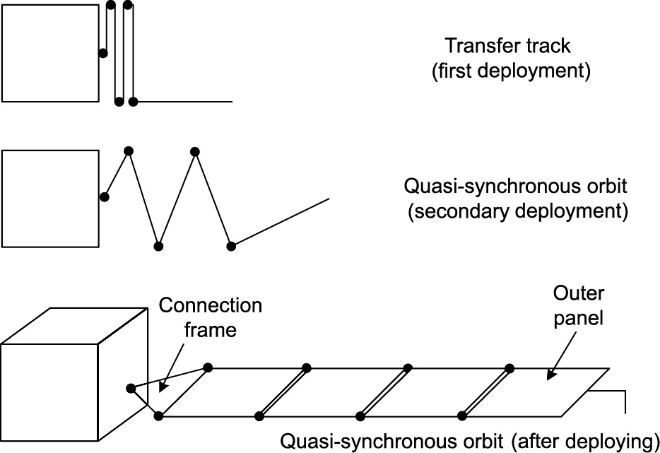
Fig. 7. On-orbit deployment process of the secondary deployment solar array.
《Table 2》
Table 2 Performance comparison of rigid solar arrays in China and in Europe.

CFRP: carbon-fiber-reinforced plastic.
The optical observation, needed by remote-sensing satellites for natural wealth observation, requires a high deployment frequency (0.25–5.00 Hz) of space solar arrays. The solar array of this type of satellite is usually parallel, with compact configuration characteristics, close contact with the satellite, and small moments of inertia, which facilitate satellite maneuvering. The solar wings are arranged parallel to the deployment axis.
A pole-type solar array is a highly rigid and lightweight solar array with lockable roots. Solar panels are directly connected to the satellite sidewall structure through the root hinges [50]. To meet the requirements of agile satellites for fast on-orbit attitude maneuvering and to realize the high-rigidity design of the solar array, a strut-type solar array with auxiliary supports can be adopted, as shown in Fig. 8.
《Fig. 8》

Fig. 8. Configuration of a strut-type solar array in the deployed state. (a) Configuration of solar array with auxiliary supports; (b) configuration of platform.
The power demand of large communication platforms is constantly increasing. Due to the limitation of the launching envelope, the area of a single solar panel cannot be interminably increased. Therefore, the only way to increase the output power of the solar cell array is to increase the number of solar panels. If a 1D deployment scheme is adopted, the solar array will be in the form of a long strip with low rigidity after deployment, which will significantly impact the satellite’s flight attitude control. Therefore, a 2D secondary deployment method is usually applied when the number of single-array solar panels reaches six to eight. In this method, the hinge axes connecting the solar panels are in the same plane after deployment but are not all parallel to each other, as shown in Fig. 9. A multi-deployable solar array has multiple deployment stages with a stable state in the middle. This measure is mainly used in cases when there is a small power supply and large orbital load during the transfer orbit flight of a high-orbit satellite. For example, the DFH-5 platform, which is China’s newgeneration communication platform, has 2D multiple deployable semi-rigid solar arrays comprising one connection frame and six solar panels, as shown in Fig. 10.
《Fig. 9》
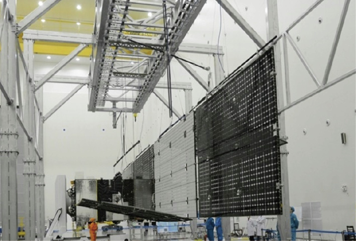
Fig. 9. A 2D multiple deployable semi-rigid solar array.
《Fig. 10》
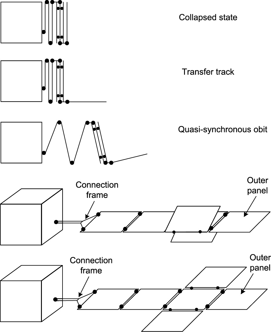
Fig. 10. The 2D multiple deployable semi-rigid solar arrays on the DFH-5 platform.
When the 2D multiple deployable solar arrays is used, the energy demand increases from less than several kilowatts to dozens of kilowatts, and will reach the megawatt level in future. The large deployable flexible solar array is a major development direction toward meeting the energy demand of large spacecraft. The first flexible solar-array system for China’s space station was successfully deployed in 2021, as shown in Figs. 11 and 12. The generation power of a single array is 9 kW, and the extended area and extended length are 67 m2 and 12.6 m, respectively. The flexible solar array comprises six sets of active mechanisms and 12 sets of passive mechanisms. The folded thickness of the flexible solar array is approximately 16.8 mm, which is only 1/60th that of the rigid solar array. The flexible substrate comprises an ultra-thin lightweight composite plate with a thickness of approximately 0.3 mm.
《Fig. 11》
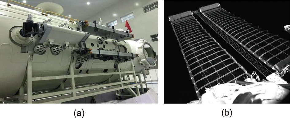
Fig. 11. The flexible solar array on China’s space station. (a) Configuration of solar array in folded state; (b) solar array in deployable state on orbit.
《Fig. 12》
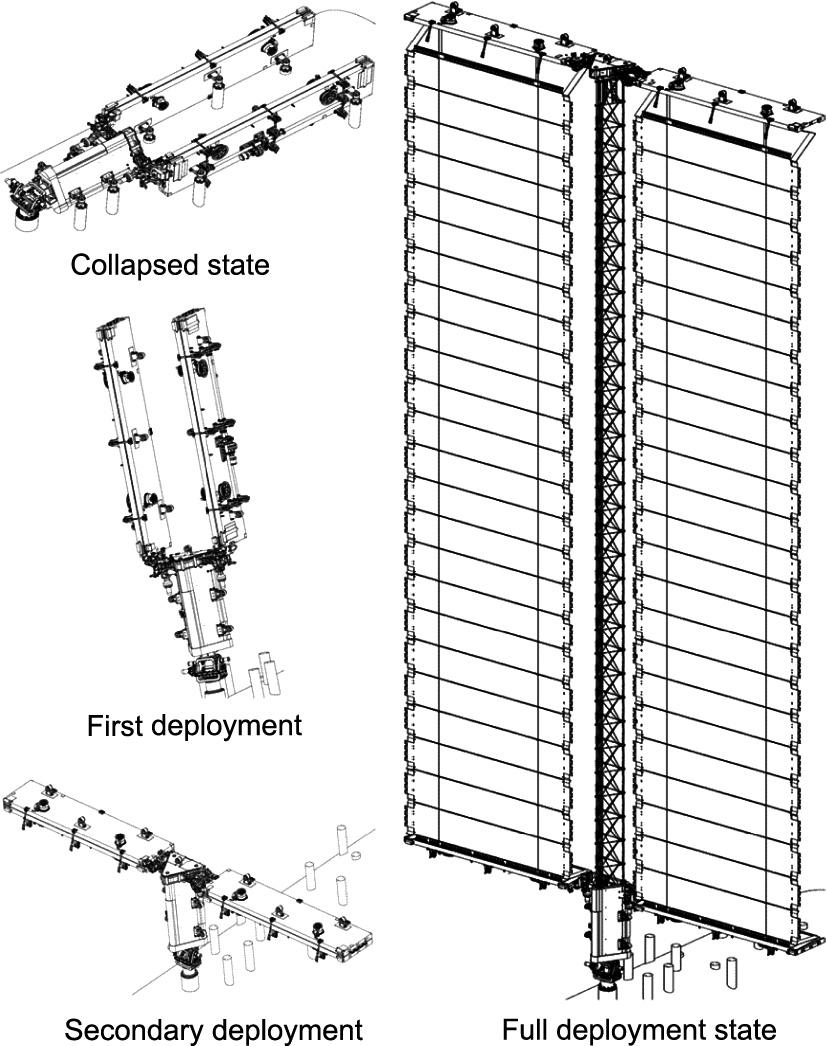
Fig. 12. The on-orbit deployment process of the flexible solar array.
The circular solar array being developed in China has a type of solar array with an approximately circular shape after deployment. The solar cells are pasted on numerous flexible triangular films [51,52], as shown in Fig. 13. The circular solar array comprises box boards, solar blankets, pressing and releasing devices, and central unfolding mechanisms. The solar blanket is composed of flexible triangular films and solar cells pasted on the film.
《Fig. 13》
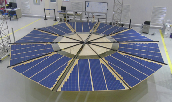
Fig. 13. The circular solar array.
In 2006, a sunlight-stimulated solar-array substrate prototype was developed based on a carbon-fabric-reinforced SMPC. The prototype, which was named Mission SMS-I, completed the deployment test in geostationary orbit [53]. Compared with conventional solar arrays, Mission SMS-I integrates a conventional substrate, support structure, and deployment function. In addition, it has a simple design without complicated mechanical parts. As a result, Mission SMS-I is China’s pioneering SMPC orbital experiment and the world’s first SMPC geostationary orbit experiment, shown in Fig. 14.
《Fig. 14》
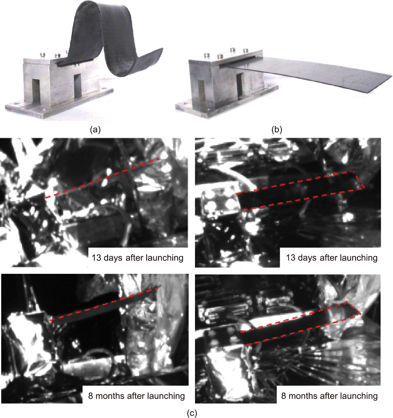
Fig. 14. Mission SMS-I. (a) The packaged configuration; (b) the deployed configuration; (c) orbital images 13 days and eight months after launching.
In 2020, a flexible solar-array system using an SMPC-flexible solar array system (FSAS) was developed that realized the onorbit deployment of a flexible solar array based on an SMPC for the first time in the world [22]. The SMPC-FSAS is driven and deployed by a lenticular tube composed of an SMPC, which is folded in the form of a curl during the launch and then locked by the locking mechanism of the cyanate-based SMPC. After entering orbit and unlocking, the deployment of the flexible solar array is driven by the lenticular tube, as shown in Fig. 15.
《Fig. 15》

Fig. 15. On-orbit releasing and deployment demonstration of the SMPC-FSAS flight hardware. (a-i) and (a-ii) Unlocking process in space; (b-i)–(b-iv) deploying process in space.
《2.3. Deployable structures and mechanisms in deep-space exploration》
2.3. Deployable structures and mechanisms in deep-space exploration
Deep-space exploration is discovering the distant regions of outer space. China is critically transforming from a strong nation to a powerful nation in the field of deep-space exploration. China has formulated a set of development plans for exploring the Moon, Mars, Jupiter and its satellites, asteroids, comets, and the solar system boundary. At present, China has begun the construction of scientific research stations on the Moon and Mars and plans to launch manned lunar missions in due course [54,55].
The CE-3/CE-4 rover, also known as the Yutu rover, is shown in Figs. 16 and 17 [56,57]. Its deployable structures and mechanisms include the mechanical parts of solar arrays, masts, and robotic manipulators, which belong to the structure and mechanism subsystem. To reduce the consumption of system resources, the moving part of the right solar array achieves directional rotation to the Sun by using a single-degree-of-freedom stepper motor, and the left solar array is unfolded and locked by elastic components. The left solar array cooperates with the thermal control subsystem to cut off the heat exchange between the cabin and the external environment by folding the solar array to cover the heat-dissipation surface. This cooperation addresses the problems of thermal control and heat preservation under the low-temperature environment of the moonlight during power failure without spontaneous heat from the whole machine. A system design involving mechanism function multiplexing is also adopted, and the pointing mechanism of the camera and directional antenna is integrated on the mast. The mast, which has three degrees of freedom, is designed to realize antenna orientation to the ground and camera imaging in the surrounding 360° range.
《Fig. 16》
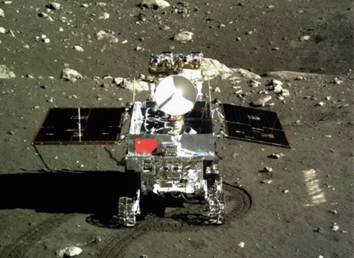
Fig. 16. The CE-3 rover.
《Fig. 17》
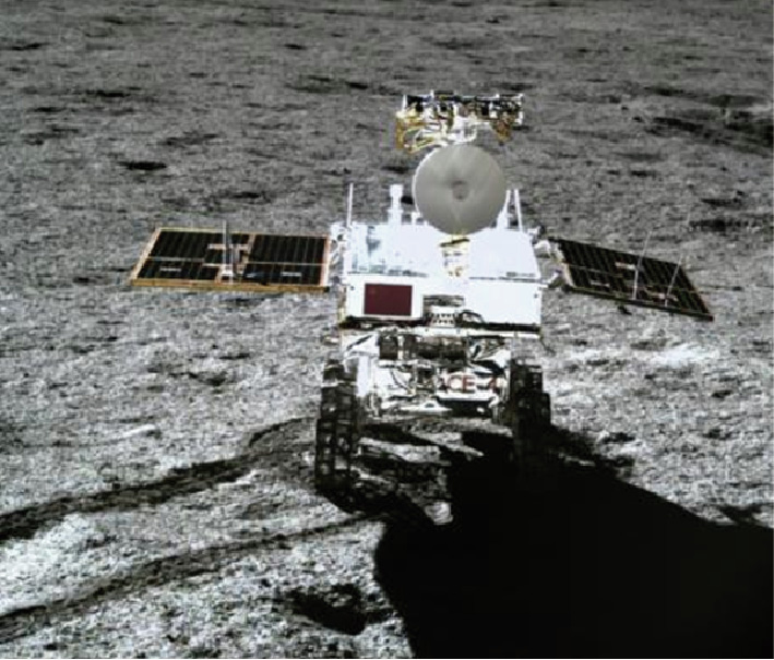
Fig. 17. The CE-4 rover.
SMPCs, as an intelligent material, has the ability to maintain the temporary shape and recover its original shape under environment stimuli (e.g., heat, magnetism, electricity, etc.). This intelligent material was also applied to fly the Chinese national flag on the red planet during China’s first Mars exploration: Tianwen-1 [58,59]. The mechanism was inspired by an ancient papyrus scroll and enabled a dynamic demonstration with the Martin wind, as shown in Fig. 18. This validation has extended this intelligent material’s application from geostationary orbit to deep space. More breakthroughs with this intelligent material can be expected.
《Fig. 18》
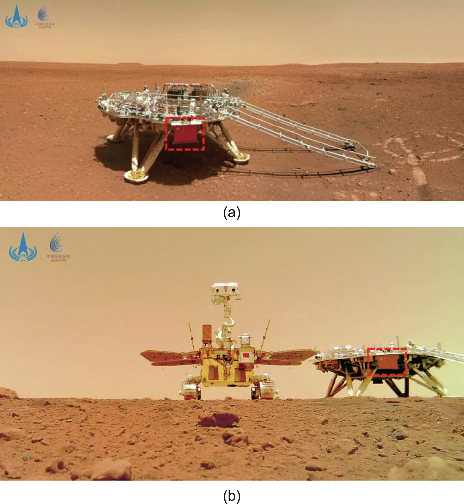
Fig. 18. Deployment on Mars, with China’s national flag framed in red. (a) The lander of Tianwen-1; (b) the rover of Tianwen-1.
《3. Key technologies of space-deployable structures》
3. Key technologies of space-deployable structures
《3.1. Space-deployable mechanism design》
3.1. Space-deployable mechanism design
3.1.1. Configuration design technology of large-scale deployable mechanisms
The configuration design of a space-deployable mechanism needs to simultaneously consider the mechanical characteristics of deployment stability, synchronization, singularity avoidance, and the structural characteristics of shape accuracy, a large storage ratio, and high rigidity. In addition, the deployment process of the deployable mechanism has different topological structures and different mathematical–physical models. The topology of the mechanism configurations is unsteady. Therefore, studying the theoretical configuration design method of large-scale deployable mechanisms is necessary in order to consider the effects of multiple configurations with variable topology.
3.1.2. Error analysis and precision design technology of large-scale deployable mechanisms
Limitations of the manufacturing process and assembly, as well as the influence of an extreme space environment, result in largescale deployable mechanisms inevitably having multiple error sources, such as dimensional errors of components, gaps of kinematic pairs, and thermal deformation of parts. Due to mechanical movement and posture change, the transmission of mechanical errors can cause uncontrollable configuration changes, resulting in mechanical failures such as unsynchronized movement, jamming, and deformation. Therefore, it is essential to carry out error analysis and precision design for large-scale deployable mechanisms.
3.1.3. Potential kinematic singularity during the design and formation of a deployable structure
A large-scale deployable mechanism is a dynamic system with multiple closed loops in space and a flexible structure. The deployment of mechanisms is a complex process of transformation from mechanisms to structure. In addition, there is a potential singularity of motion in the deployment process of the mechanism. This bifurcation/multi-bifurcation behavior has been reported in related studies. Mobility and singularity analysis [60,61], mobility and multi-furcation analysis [62], low-order symmetrical mechanism modes, and bifurcation behavior analysis [63] of deployable mechanisms are necessary.
《3.2. Reflector-forming design technology for space-deployable cablemembrane structures》
3.2. Reflector-forming design technology for space-deployable cablemembrane structures
A cable-membrane structure is a form of space structure in which high-strength membrane materials and cables form a certain shape in space by producing a certain prestress. The key factors affecting the accuracy and stability of space-deployable cable-membrane structures include the topological configuration, geometric layout of the reflector mesh, and tension distribution of the cable membrane. In addition, the following vital technologies are involved:
(1) Principal error analysis and design technology. The reflectors of mesh antennas are formed using small triangular or quadrilateral facets to approximate a paraboloid. Correct evaluation of the approximation error is the prerequisite for designing highprecision mesh reflectors. To obtain the minor principal error, a smaller facet size is required, which means a large increase in the number of nodes and cables. The greater number of nodes and cables results in more difficulty during the manufacturing, assembly, and debugging processes. Consequently, it is necessary to study an efficient principle error analysis and design method [64,65].
(2) Generation technology for static and motion deterministic topology. For space mesh antennas, the repeatable deployment accuracy requires motion and static determinacy of the structure. The static and motion determinacy configuration ensures the dimensional stability of the mesh surface from the topological structure under external load. Furthermore, with motion and static determinacy, it is easy to apply balanced pretension to obtain the required structural rigidity [66].
(3) Coupling design technology of geometry and pretension. The reflective surface of a mesh antenna is formed by the flexible stretched cable-membrane structure. The cable-membrane material itself cannot be compressed or bent. Thus, appropriate pretension must be introduced in the cable-membrane structure for its smooth operation. As shown in Fig. 19, a geometry and pretension coupling design is required to simultaneously ensure the high surface accuracy of the reflector, the anti-interference ability of the antenna, and uniform tension in the cables [67–69].
《Fig. 19》

Fig. 19. Geometrical formation method of the geodesic on the mesh reflector. Eci: the ith reference ellipse; Sci: the ith reference circle; Ni,j: the jth node on the ith ring on ellipsoid reference;  : the jth node on the ith ring on spherical reference; Bm: boundary element;
  : the chords between every two neighbor nodes on the ith ellipse; Ri: the radius of the ith circle; n: number of mesh segments; D: antenna aperture.
(4) Performance-degradation prediction and compensation technology. The composite materials used in space structure components result in performance degradation during space service. This is because their stress–strain relationship is manifested as nonlinear viscoelasticity related to the coupling of time, stress, and temperature. To reasonably evaluate or prolong the service life of space structures, it is necessary to develop methods for nonlinear viscoelastic mechanical modeling under multi-source nonlinearity coupling, precision passive-design compensation technology, on-orbit high-precision active adjustment, and compensation technology.
《3.3. Dynamic analysis of space-deployable structures》
3.3. Dynamic analysis of space-deployable structures
A space-deployable structure has two states: folded and deployed. Its deployment process involves a dynamic problem of a flexible multibody system. To ensure the dynamic performance of deployable structures in complex space environments, the following key technologies must be considered.
(1) Dynamic modeling and solution technology for the deployment process. Deployable space structures contain large flexible components, such as cables, membranes, and thin shells. Contact winding and hooking may occur between a cable and a cable or a cable and a truss during deployment. To avoid these phenomena, mesh management is required. For the deployment of membrane structures, it is necessary to study the influence of the folded state on contact collision during the deployment process and that of the crease on the on-orbit working surface accuracy. Therefore, it is necessary to accurately model the rigid-flexible coupling of the large-scale motions of flexible space-deployable structures [70] and to use dynamic analysis to obtain the force state during the deployment process in order to optimize the configuration and scale of the structure.
(2) Reliability design and control technology for the deployment process. The deployment process, from an unstable state to a stable state, is one of the most likely failures of a space-deployable structure, such as structural damage, improper deployment. Therefore, the reliability of deployable structures largely depends on critical design parameters. Deployment process control design is mainly used for motion planning of the deployment process. An inverse dynamic analysis obtains the driving-force spectrum of the deployment process to control the deployment time and reduce the impact after on-orbit locks.
(3) Dynamic analysis and design technology in space environments. A space-deployable structure is subjected to strong vibrations and huge shocks during launching. Furthermore, it operates in outer-space environments, under conditions such as weight loss, radiation, and temperature alternations of ±170 °C. Thus, it is necessary to ensure the optimal structural dynamic performance under both the folded and deployment states. Doing so involves the comprehensive design technology of the dynamic performances of the two states. In addition, it is necessary to study the thermally induced vibration of space structures under thermally alternating environments [71,72].
《3.4. Environmental adaptability and ground validation》
3.4. Environmental adaptability and ground validation
Space-deployable structures are generally installed outside the spacecraft cabin and are directly affected by the extreme conditions of the space environment. Therefore, to ensure a successful launch, reliable deployment, and stable operation of a spacedeployable structure, technologies for conducting verification tests on the ground using simulated environments should be considered in the development stage. The following key technologies are involved in environmental adaptability and ground verifications.
(1) Technology for mechanical adaptability to the environment. The launch environment includes the environment during the power-flight phase of the launch vehicle and the separation phase of the satellite and rocket. The mechanical environmental load generated by the launch vehicle is transferred to the deployable structure through the spacecraft platform, including acceleration, sinusoidal vibrations, random vibrations, noises, and shocks. In addition, as the spacecraft enters the predetermined orbit, the deployable structure may be subjected to other loads, such as shocks and vibrations, caused by the structure’s normal operations.
(2) Technology for thermal adaptability to the space environment. Successful deployment of space-deployable structures is the result of the combined functioning of all relevant mechanisms and structures. Temperature conditions are a prerequisite for good combined functioning; therefore, the thermal design must ensure that all components work properly and function together well under the extreme temperature conditions. After the deployable structure completes deployment in orbit, large external temperature alterations and internal temperature differences will cause structural deformations [73]. Therefore, necessary ground tests should be conducted to verify the structural performance during the development process.
(3) Technology for other types of adaptability to the space environment. Space-deployable structures are inevitably affected by the conditions of the space environment, which include radiation, atomic oxygen, and a vacuum, and can change the material performance, mechanism function, and overall performance of deployable structures. Therefore, in the design stage of a deployable structure, an environmental adaptability analysis should be conducted, and materials and types of thermal-control coating should be carefully selected according to the orbital environment and expected lifespan of the spacecraft structure.
(4) Ground validation technology. The on-orbit deployment environment, including weightlessness, vacuum, and high and low temperatures, is different from the ground deployment environments. These differences significantly influence the structural performance and mechanical properties of deployable structures [74–77]. Due to the large number of moving parts and the complex deployment process, sufficient and reasonable ground verifications must be performed in a simulation environment during the development phase of space-deployable structures.
《4. Development and trends of space-deployable structures》
4. Development and trends of space-deployable structures
Space-deployable structures are playing an increasingly important role in the fields of radio astronomy, mobile communications, space sciences, and deep-space exploration. Therefore, to adapt to these rapid developments and increasing requirements, in-depth research on the following components of space-deployable structures is required.
《4.1. Mesh antennas》
4.1. Mesh antennas
With the continuous development of space technology and increasing number of applications in mobile communications and deep-space exploration, large-scale space mesh antennas are playing an increasingly important role in the field of space-deployable structures.
4.1.1. Single ultra-large deployable antennas
Compared with multi-module and on-orbit assembled antennas, a self-deployment antenna completes the process from retraction to deployment by relying on its own deployment mechanism. Despite its various disadvantages, which include relatively poor performance, high launch construction costs, and poor technical maturity, the single self-deployment method is an implementation method for achieving ultra-large antennas in some space missions. For such antennas, it is necessary to research the new structure/ mechanism design technology with a high storage ratio.
4.1.2. Lightweight and high-storage-ratio miniaturized mesh antennas
Future space satellites, especially commercial space satellites, are being rapidly developed in the areas of miniaturization and networking. A small mesh antenna exhibits advantageous characteristics such as a high storage ratio, light weight, low cost, and flexible configuration; thus, it can provide a simple, reliable, and lightweight deployable antenna for a micro–nano satellite platform. The main structural forms of small mesh antennas in commercial aerospace include folding-rib antennas, winding-rib antennas, tension-truss antennas, loop-pole antennas, deployable parabolic cylindrical antennas, and deployable membrane antennas.
4.1.3. Mesh antennas with active feed
Traditional large antennas can be divided into two systems: reflective-surface and phased-array antennas. A reflective-surface antenna has a simple system and light weight, which are more suitable for aerospace applications. A phased-array antenna has flexible beams and a fast scanning speed, but the system of phased-array antennas is relatively complex and heavy, and presents difficulty in achieving a large diameter in orbit. Therefore, a new system antenna should be developed that combines the advantages of the reflective-surface and phased-array antennas. This new type of system antenna could achieve a certain range of electrical scanning and higher gain through its reflective surface. For example, in communication satellites, phased-array feeds can be used to automatically control the beam direction and increase the number of beams, and a reflective surface can be used to increase the antenna gain. In parabolic cylindrical antenna applications, a phased-array feed is used to realize 1D scanning and 1D focusing. This method can meet the requirements of various space missions.
4.1.4. Electrostatic formed membrane reflector antenna
Thin-membrane reflector antennas have the advantages of high precision, light weight, small size, and easy folding and deployment. An electrostatically formed membrane reflector antenna uses boundary cable forces, gas pressures, and electrostatic forces to ensure the surface accuracy of a membrane reflector formed of aluminized polyimide. Compared with mesh antennas, electrostatically formed membrane reflector antennas can be extended to X, Ku-band, or higher frequency bands and can achieve active surface control through electrostatic adjustments. Therefore, they represent an important development direction for ultra-light, high-precision, and large-aperture space antennas in the future [78,79].
《4.2. Solar arrays》
4.2. Solar arrays
With the development of space technology, the demand for solar arrays is changing and showing different requirements. In the field of communication, the power demand for solar arrays has increased from 10 to 30–50 kW. Moreover, there is a need for mass-produced, small-envelope, and low-cost low-orbit constellations of satellites. In remote-sensing fields, on the other hand, the primary requirement is high stiffness. Thus, development of solar arrays has entered a new stage.
4.2.1. Solar arrays with light weight and a high storage ratio
The folded envelope and weight of a rigid/semi-rigid solar array are approximately proportional to their expanded area. However, this characteristic cannot meet the requirements of ultra-high-power spacecraft. In particular, when an array’s envelope is too large, it will exceed the carrying capacity. In addition, the folded envelope and weight of a flexible solar array exhibit significant nonlinear characteristics with their expansion area. With an increase in the expansion area, the weight and folded envelope increase relatively gradually. Therefore, flexible solar arrays are especially suitable for spacecraft that require ultra-high power and a large envelope. With continuous improvement in raw materials and production technologies, winding flexible solar arrays have once again become a research hotspot in various countries with cutting-edge aerospace development. Based on their technical indicators, such as their envelope and power-weight ratio, such products are expected to become upgraded substitutes for traditional rigid and semi-rigid solar arrays.
4.2.2. Ultra-flexible solar-array technology based on flexible battery pieces
As significant breakthroughs have been made in battery technology, particularly in the research of high-efficiency thin-film solar cell technology, solar cells can participate in the folding action of solar arrays. This will bring comprehensive innovation into the overall configuration of space solar arrays. With the innovative battery technology, a completely flexible solar blanket structure comprises thin and light thin-film solar cells and an ultra-soft substrate without the need for buffer materials. The coiled-up clamping scheme, with new battery innovation technology to achieve thin and light structure, has the advantages of an excellent storage ratio index and will become the mainstream technical scheme for space solar cell arrays in the future.
After adopting a fully flexible solar blanket structure and the coiled-up clamping scheme, the configuration of solar arrays will change from a typical rectangular folding shape to a cylindrical and thin polygonal shape. As a result, the overall layout of the spacecraft will also be considerably simplified. These solar arrays will exceed existing products by far in terms of scalability, folded envelope, and weight power ratio. They will also be significantly superior to existing flexible solar-array products at home and abroad in terms of deployment stiffness, deployment inertia, and overload resistance.
4.2.3. Modular and replaceable solar-array technology
With the increasing demand for ultra-large solar arrays and the need to demonstrate solar power stations in space and other projects, foreign countries have invested huge funds in conducting such research. At present, relevant technical research is also being conducted in China. However, considering that the power demand is above the megawatts level, it is not reasonable to use a single solar array to realize this function. Therefore, on-orbit assembled solar arrays and modular replaceable solar arrays have become a key development direction in this field.
《4.3. Deployable mechanisms》
4.3. Deployable mechanisms
Deployable mechanisms exhibit two states: folded and deployed. The following key technologies are required to ensure the overall performance of deployable mechanisms in complex space environments.
(1) An integrated design of deployable mechanisms and the satellite platform. For ultra-large space-deployable mechanisms, the scale of the satellite platform is much smaller than that of the deployable mechanisms after expansion. The traditional design method, which considers the satellite platform as the overall structure and the deployable mechanism as the effective load, is not suitable for large-scale deployable mechanisms. Thus, ultra-large deployable mechanisms have become the main structures of the spacecraft. As the service platform, the satellite body provides communication, navigation, measurement and control, propulsion, and energy for deployable mechanisms. Thus, deployable mechanisms and the satellite platform are an integral organic whole. It is necessary to export the design input of the satellite platform according to the functional requirements of the deployable mechanisms to realize their integrated design. However, at present, there is no mature integrated design method.
(2) New materials in lightweight structure design. Traditional deployable mechanisms are mostly truss structures, which are mainly composed of rigid rods and joint hinges and are controlled by motors. With the size enlargement of deployable mechanisms, their ontological requirements increase sharply increases sharply. Hence, achieving a lightweight design for deployable mechanisms is a key issue that needs to be addressed. Recently, new materials have been increasingly applied for deployable mechanisms; for example, ordinary metal materials can be replaced with carbon fiber composite materials, rigid components can be replaced with flexible cables, motor driving can be replaced with intelligent composite materials, and rigid antenna panels can be replaced with thin-film materials. The application of new materials considerably reduces the weight of deployable mechanisms; however, it also decreases the system stiffness, which affects the stability of onorbit work. Therefore, it is necessary to improve the system’s stiffness through a multi-configuration structural optimization design.
(3) Dynamics and control of ultra-large complex systems. An ultra-large deployable mechanism is a large flexible system in orbit. The first natural frequency of the system is even lower than 0.1 Hz, and its dynamic behaviors are extremely complex. A deployable mechanism comprises massive rods, cables, and nets (or membranes). Because it has massive flexible components, the traditional finite-element dynamic model is not applicable. Although the recently developed absolute node coordinate method can address large flexible problems, it cannot solve the dynamic analysis of large-scale flexible structures and has difficulty meeting the requirements of computational time and efficiency. The dynamic modeling and analysis of ultra-large complex flexible systems are the key problems presented by deployable mechanisms. In addition, ultra-large deployable mechanisms significantly influence the dynamics and attitude control of satellites. Due to the problems of great flexibility and high inertia that such mechanisms present, it becomes extremely challenging to maintain the attitude control and orbit adjustment of satellites.
(4) Ground experimenting and testing on large flexible deployment mechanisms. At present, 2D gravity-compensation technology is relatively mature, while spatial 3D gravitycompensation technology is not yet perfect. In particular, largescale 3D gravity compensation remains a difficult problem for deployable antennas. A photogrammetry system is generally used to measure the surface accuracy for large flexible deployable mechanisms. Existing non-contact laser vibrometer technology cannot complete modal vibration tests of a full-scale prototype. Therefore, working performance parameters of full-size on-orbit antenna mechanisms are tested on the ground using a reducedscale or local prototype, and then predicted by means of simulation software and ground test data. Thus, it is necessary to establish a space–ground integrated verification system for virtual simulations and ground physical tests of large deployable mechanisms.
《4.4. On-orbit surface adjustment》
4.4. On-orbit surface adjustment
On-orbit antenna systems show an increasing trend of requiring a light weight, high accuracy, and high frequency band. Thus, research on active accuracy control and adjustment is of great academic and engineering significance for the development of spacecraft. The following technologies are important for developing active accuracy control and adjustment.
4.4.1. On-orbit surface adaptive compensation technology for solidsurface antennas
The high requirements for millimeter- and submillimeter-wave remote-sensing loads include a need for large-scale, high-accuracy, and lightweight reflectors. The main factors affecting the surface accuracy of solid-surface antennas are manufacturing errors, assembly errors, and on-orbit thermal deformations. Therefore, it is necessary to develop high-accuracy intelligent materials and structures to compensate for the surface error of the reflector.
4.4.2. On-orbit reconfigurable antenna technology
Traditional antenna systems use a reflection surface with a fixed irradiated service area, which limits the usage range. Through the use of new materials and actuators, reconfigurable antennas can be developed that possess a changeable contoured beam that can irradiate multiple service areas. Such antennas have the advantage of enabling multi-purpose satellites and thereby saving on launch costs.
4.4.3. Deployable thin-film optical technology
A thin-film diffraction space system has the advantages of light weight, large diameter, and loose tolerance. Such a system can significantly reduce the volume and weight in spacecraft launching stage, manufacturing difficulty, and cost of emissions. However, it is difficult to control the shape accuracy due to the thinness of the film. Thus, new technologies in spacecraft, structures, and actuators are needed to compensate for the surface deviations caused by thermal alternations and large-temperature gradients in space.
4.4.4. On-orbit active pointing and focusing adjustment technology
Due to assembly, thermal-deformation, and deployment errors of the extension arm of a satellite platform, antenna-beam pointing deviation and performance degradation will occur. Therefore, onorbit active pointing and focus adjustment techniques are required to improve the beam-pointing performance and on-orbit stability.
《4.5. On-orbit assembly and construction technology》
4.5. On-orbit assembly and construction technology
Examples of future kilometer-level ultra-large spacecraft include solar power stations in space, ultra-large space loads (SAR and space-based radar), ultra-large space science exploration detectors (very-long-baseline interferometry (VLBI), space-based telescopes), and future space cities. Ultra-large spacecraft will play an increasingly important role in space activities, such as future space resource utilization, high-resolution earth observations, cosmic mystery explorations, and long-term on-orbit residence. Limited by the individual launch capability of launch vehicles, one of the most promising construction methods for ultra-large space structure systems is to complete modular deployable structure design, multiple launches, and on-orbit assembly. Therefore, it is necessary to study the on-orbit assembly technology of deployable structural modules with or without human participation. In addition, compared with single-body deployment mechanisms and on-orbit assembly schemes, on-orbit construction is less constrained by carrying capacity and has the advantages of lower cost and greater expansibility. Therefore, on-orbit construction will gradually become the most effective way to construct and maintain kilometer-level ultra-large space structures. Intensive research on new technologies, such as on-orbit self-assembly and on-orbit additive manufacturing for space-deployable structures is necessary.
《5. Conclusions》
5. Conclusions
With the development of aerospace technology, spacedeployable structures are playing an increasingly critical role in the field of space activities and exploration. Significant progress and achievements have been made in the research of key technologies of deployable structures in China. However, the relevant theoretical and experimental research is not yet sufficiently systematic and mature. This paper summarizes recent progress made in the research of deployable structures in China, presents the problems that require further study in order to adapt to the development of future space technologies, and proposes possible solutions for current technological challenges. The contents of this paper will provide a solid reference for further systematic research on the next stage of deployable space structures.
《Acknowledgments》
Acknowledgments
We acknowledge financial support from the National Natural Science Foundation of China (11290154 and U20B2033).
《Compliance with ethics guidelines》
Compliance with ethics guidelines
Xiaofei Ma, Tuanjie Li, Jingya Ma, Zhiyi Wang, Chuang Shi, Shikun Zheng, Qifeng Cui, Xiao Li, Fan Liu, Hongwei Guo, Liwu Liu, Zuowei Wang, and Yang Li declare that they have no conflicts of interest or financial conflicts to disclose.


 京公网安备 11010502051620号


