

《1. Introduction》
1. Introduction
The reusable launch vehicle (RLV) technique is an effective method for achieving cost-effective and reliable space transportation ranging from national space activity to commercial space launch industry [1]. Consequently, it has progressively become a dominant trend with urgent demands in terms of rapid prototyping and emission density enhancement [2]. Through the recovery and re-use of recyclable launch system components that require extensive refurbishment, the overall cost of using space for communication, reconnaissance, and civil remote sensing can be dramatically reduced; thus, enabling more affordable access to explore and exploit space resources [3].
The advantages of applying vertical landing recycling compared to drogue parachute and airfoil plans lie in its small landing area and relatively easy implementation/maintenance. Because the landmark recycling tasks have been successfully achieved by Blue Origin’s New Shepard [4] and SpaceX’s Falcon series [5], the vertical landing recycling regime is considered as the preferred choice for private space agencies [6–8]. Stable landing, the ultimate stage of the entire recycling procedure is vital to the success of the RLV technique implementation. Legged landing mechanisms adopted in the New Shepard capsule and the Falcon-9 rockets provide greater reliability and feasibility for executing soft landing with sufficient safety. Such applications can be dated back to the Apollo lunar module, wherein a four-legged assembly constructed of aluminum-alloy tubing with energy-absorption honeycomb cartridge serves as support for landing gear to adapt to lunar terrains [9]. Moreover, a similar structure with reformative telescopic mechanism has been employed in the ground supporting systems of the delta clipper-experimental (DC-X) [10] and DC-X (advanced) prototype [11].
In contrast to using truss-type structure/mechanism to create landing support system, contemporary RLV prototypes fully leverage the advantages of deployable mechanism featuring high deployed/folded ratio, large landing support region, and highefficient buffering against landing impact. A group of parallel linkage mechanisms with hydraulic buffer element was employed in the New Shepard rocket to provide soft landing at the final stage of recovery [4]. The four-legged landing mechanism could be completely folded inside the cabin without interfering with the aerodynamic characteristics at lift-off. Furthermore, the Falcon series rockets also utilized the four-legged deployable mechanism as the landing support system with multi-stage cascaded telescoping structure, thereby providing large ground support region to guarantee stable landing of the vehicle [12].
In addition to the aforementioned practical achievements, substantial efforts have been devoted to investigating landing dynamics and performance optimization of key components in RLV. Aiming at shedding light on the parametric insight of landing performance, Zhang et al. [13] established a dynamic simulated model with variation of initial motion/posture states to identify extreme landing conditions for the RLV. A more advanced version was presented in Ref. [14], wherein the landing strut flexibility of the RLV was considered. Thus, the planetary lander and the RLV share the common theoretical fundamentals when focusing on the ultimate stage of legged landing. A variable-damping shock absorber (SA) for the lunar lander was proposed in Ref. [15] to prevent the overall gear from overturning on inclined surface. The corresponding attitude control strategy was further proposed in Ref. [16], which was experimentally validated on a semi-active landing gear system. Hence exploiting the advantages of these research findings can benefit the design, analysis, and implementation of the legged mechanism that offers a safe and reliable landing for RLV.
This study proposed a novel legged deployable landing mechanism (LDLM) for RLV with experimental validation of the performance via deployment and soft-landing tests. The primary contributions of this study can be summarized as follows.
(1) The non-dominated sorting genetic algorithm-II (NSGA-II) evolutionary algorithm was employed to establish a multiobjective optimization paradigm to obtain the optimal scale parameters that guide the mechanism design of the LDLM prototype. The optimized LDLM using Watt-II six-bar mechanism was endowed with advantages such as large landing support region, lightweight, and reasonable linkage internal forces.
(2) A gravity-governed deploying scheme was proposed by fully leveraging optimized Watt-II six-bar mechanism to achieve passive unfolding behavior. In contrast to the deploying strategies of existing landing gears, the proposed scheme only required a slight pneumatic initial push to trigger the LDLM without recourse to high-pressure helium resource. This avoids full-range hydraulic/ pneumatic actuation during the entire deploying stage.
(3) A fully-functional scaled RLV prototype was developed with key performance validation. The experimental results demonstrated that the devised LDLM achieved rapid and smooth deployment (duration less than 1.5 s) with mild posture disturbance to the cabin (yaw and pitch fluctuation less than 6°). In addition, it provided satisfactory impact attenuation (acceleration peak less than 10g (g is the gravitational acceleration)) at 0.2 m freefall test, thus offering a potential alternative to legged landing gear for future RLV archetype.
The remainder of this paper is structured as follows. Section 2 presents an overview of the LDLM. The multi-objective optimization for the LDLM is detailed in Section 3 along with the deploying scheme and the SA preference. Furthermore, the experimental results of deployment and soft-landing tests are presented in Section 4. Finally, the conclusions and scope for future work are presented in Section 5.
《2. Overview of the LDLM》
2. Overview of the LDLM
《2.1. General description》
2.1. General description
The LDLM, as shown in Fig. 1(a), comprises the Watt-II 6-bar linkage-based LDLM, deploying trigger device, locking mechanism, SA, and foot pad. Four identical LDLMs were well tuned and circumferentially arranged on the steel cabin of the scaled vehicle analog, as shown in Fig. 1(b). The Watt-II 6 bar linkage-based LDLM was well-chosen with optimization design to provide large landing support region as fully deployed, while exhibiting compact envelope space as fully folded. This provides facilitating conditions for the RLV at landing and lift-off stage, respectively. The deploying trigger device was pneumatic-actuated to offer instantaneous thrust to deploy each leg when switched on. Furthermore, the locking mechanism was tailor-made to provide in-position lock for the Watt linkage when the leg deployment was entirely attained. In addition, to sufficiently mitigate the foot–ground collision effect at landing, an SA canned with customized aluminum honeycomb was mounted near the foot pad for each leg.
《Fig. 1》
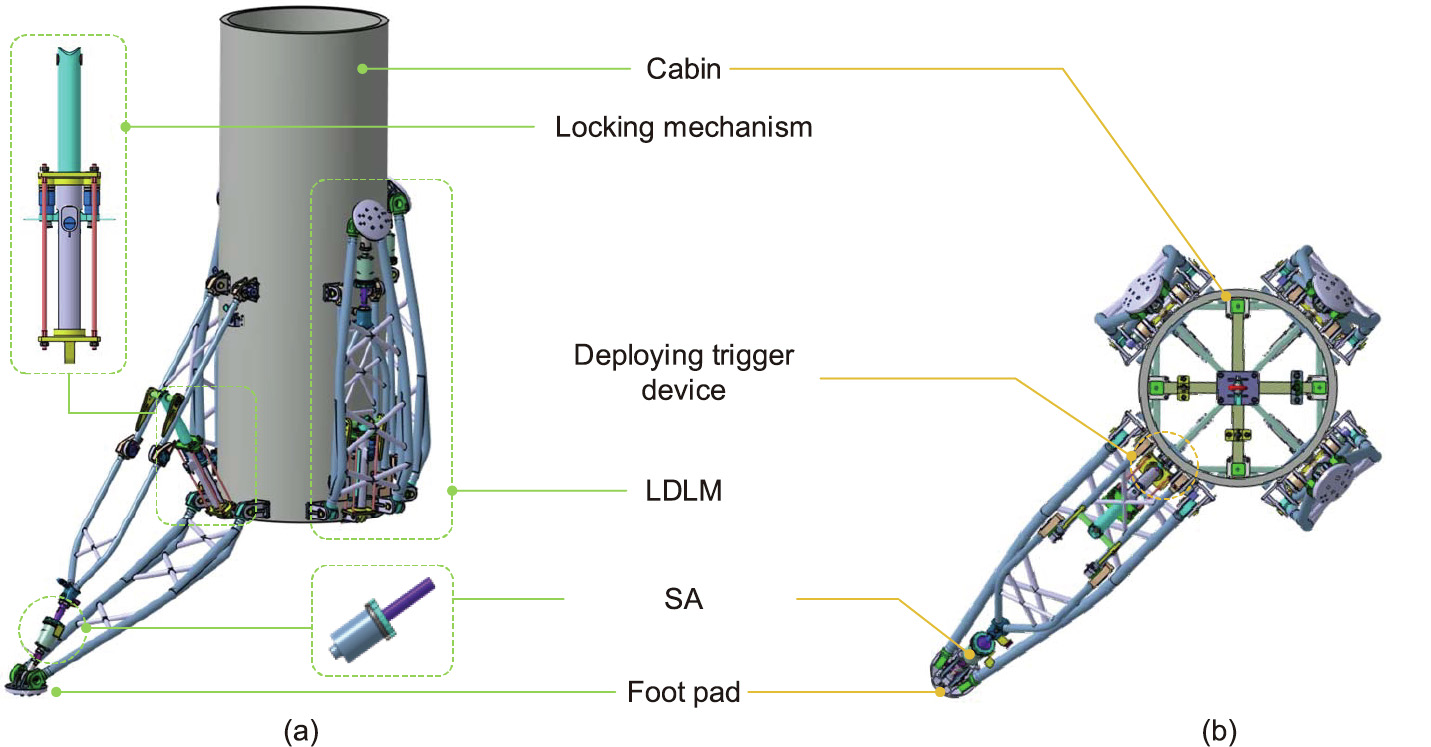
Fig. 1. Structure of the Watt-II 6-bar linkage-based LDLM for the RLV with key components. (a) 3D model; (b) top view.
The details of the deploying trigger device and the locking mechanism are shown in Figs. 2(a) and (b), respectively. Each leg was equipped with a pneumatic driven trigger device wherein the Watt-II 6-bar linkage-based LDLM was released from the initial position locker to facilitate deployment under the impulsive thrust generated by the air cylinder. Thereafter, the locking mechanism was enabled when the leg was fully deployed. Subsequently, the nested cylinder structure was applied in this scenario, wherein the upper cylinder uniaxially extended along the inner cavity of the lower cylinder during the deploying process. A two-stage spring-pin locking mechanism was devised to guarantee the reliability of the locking functionality. The primary locker restricted the fully extended upper cylinder from rebound towards the end of deployment, and the secondary locker was subsequently enabled to fix the dowel of the primary locker, thereby providing dualbackup guarantee to maintain the ultimate leg configuration when fully deployed.
《Fig. 2》
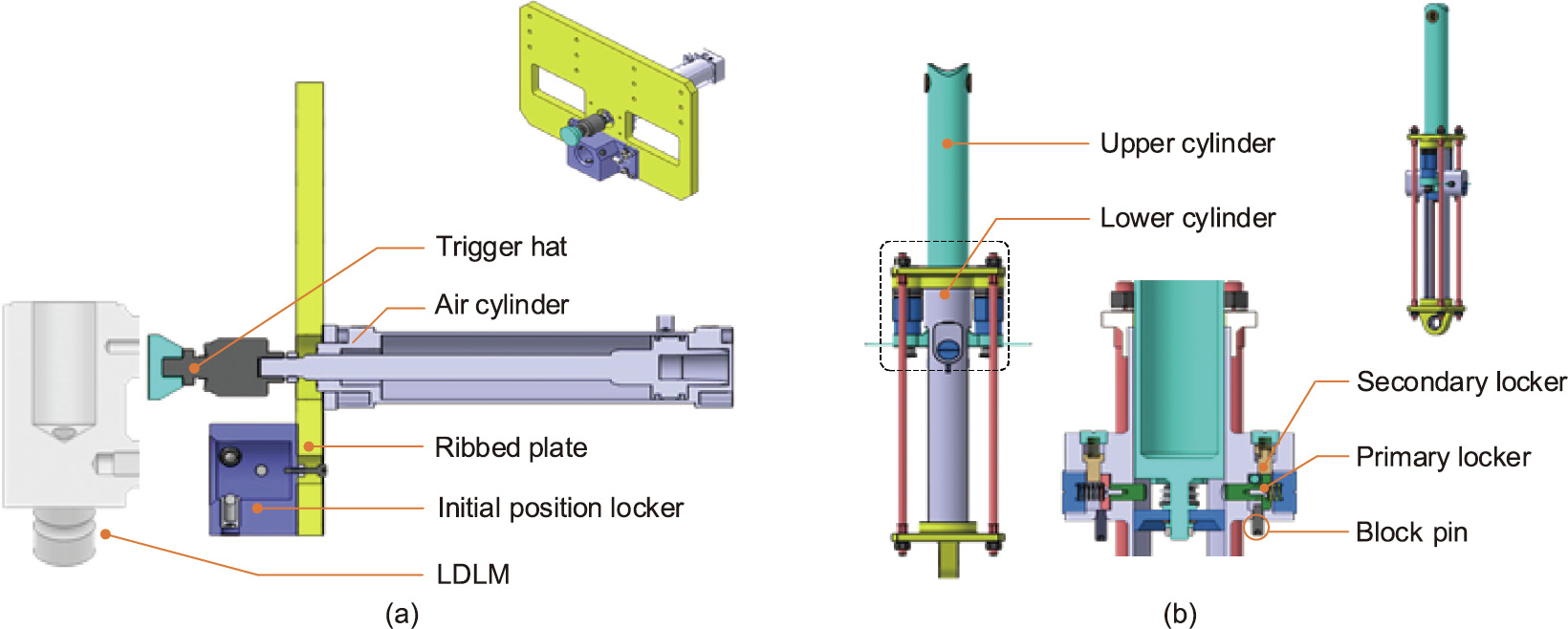
Fig. 2. Components of (a) the deploying trigger device and (b) the locking mechanism of the LDLM.
《2.2. Working principle》
2.2. Working principle
The primary working modes of the LDLMs were the deploying and locking modes. In the former mode, each leg was pneumatically triggered with initial actuation for release. When the footpad reached the bottom extreme position, the leg immediately changes into the latter mode, wherein the two-stage spring-pin locking mechanisms were entirely engaged, awaiting the sequential RLV command for vertical landing. The details of these aforementioned working modes are illustrated in Fig. 3, where the working status of the relevant auxiliary components during the entire deploying process is revealed chronologically.
《Fig. 3》
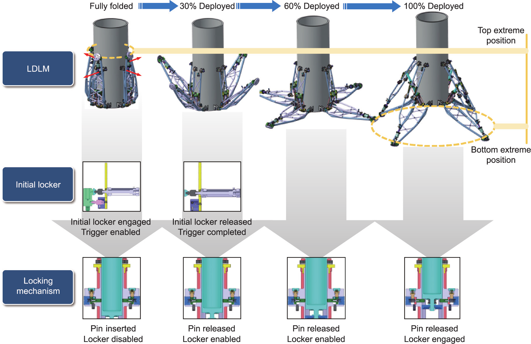
Fig. 3. Deployment process of the LDLM with the corresponding status of the key components.
《3. Development of the LDLM》
3. Development of the LDLM
《3.1. Optimization design of the Watt linkage-based landing LDLM》
3.1. Optimization design of the Watt linkage-based landing LDLM
Considering the optimization design of the landing mechanism, Fig. 4 shows the outline of the entire optimization design. The landing support region, lightweight, and low linkage internal forces properties were considered, which transformed the current design task into a multi-objective optimization problem. The procedure began with the topology selection wherein the preferred topology scheme was selected based on the evolution of the synthesis of the Watt-II mechanism template. Subsequently, the selected topology of the LDLM was parameterized to further formulate the optimization paradigm with multiple-objective functions and essential constraints. The acquired optimal scale parameters forming the fundamental configuration of the singleleg was subsequently utilized as the blueprint to fabricate the LDLM prototype. The detailed procedure has been elaborated in subsequent sections.
《Fig. 4》
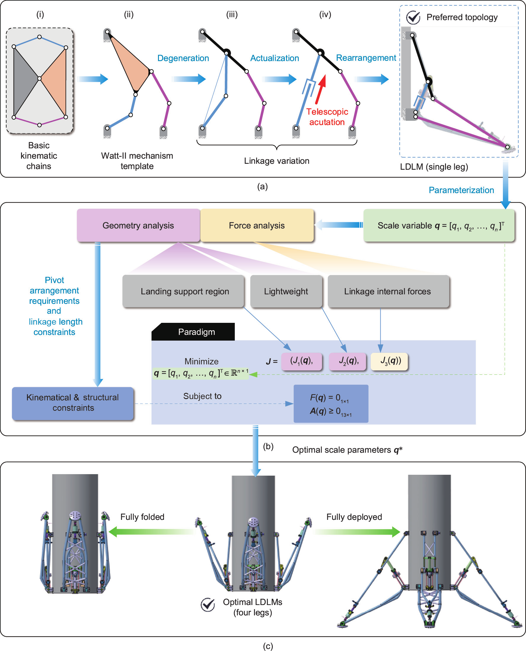
Fig. 4. Outline of the multi-objective optimization procedure for the LDLM. (a) Topology selection; (b) multi-objective optimization; (c) optimization result. q: scale vector; q1–qn: scale variables and n is the number of scale variable; q*: optimal scale parameter; J: multiple objective function vector; Ji(q): individual objective indicator (i = 1, 2, and 3); F(q): equality constraint; A(q): the composite matrix for the nonlinear inequality constraints.
3.1.1. Topology selection
The topology selection began at the origination of the basic kinematic chains ((i) in Fig. 4(a)). In contrast to traditional fourbar mechanisms that possess merely three independent links (or equivalently design variables) for the function generation problem [17], the six-bar mechanisms (i.e., Watt-II, Stephenson-II and III types) can offer sufficient design possibilities to satisfy the working requirements of the LDLM through careful arrangement of the associated control points [18]. To simplify the synthesis of mechanism and ease implementation, the Watt-II mechanism, as shown in (ii) in Fig. 4(a), was selected as the fundamental template to generate the anticipated configuration for the LDLM. Furthermore, by executing the linkage variation, as shown in (ii)–(iv) in Fig. 4(a), the preferred topology scheme was obtained and subsequently parameterized with the scale vector 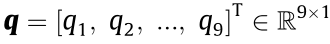 , as shown in Fig. 5.
The scale variables q1–q9 combined with three ground pivots (A, B, and C), three moving points (D, E, and F), and two auxiliary points (G and H), were utilized to represent the current topology of the to-be-designed linkage group at fully deployed condition, as shown in Fig. 5(a). To guarantee the success of the LDLM executing deploying action, the ideal configuration of the preferred WattII mechanism was set as shown in Fig. 5(b). Three additional auxiliary angular variables (α1, α2, and α3) were introduced to characterize the feasible linkage solution of the LDLM as fully folded up, whereas the angular variables (θ1, θ2, and θ3) were introduced to ease formula derivations in Section 3.1.2. Fig. 5(c) shows the landing support region of the LDLM on scheduled flat surface. Herein the diameter of the inscribed circle of the support polygon formed by four landing footpads, regarded as a generic tool to quantitatively assess the walking stability of legged robots [19–21], was employed to further evaluate the static stability margin of the LDLM when fully deployed.
《Fig. 5》
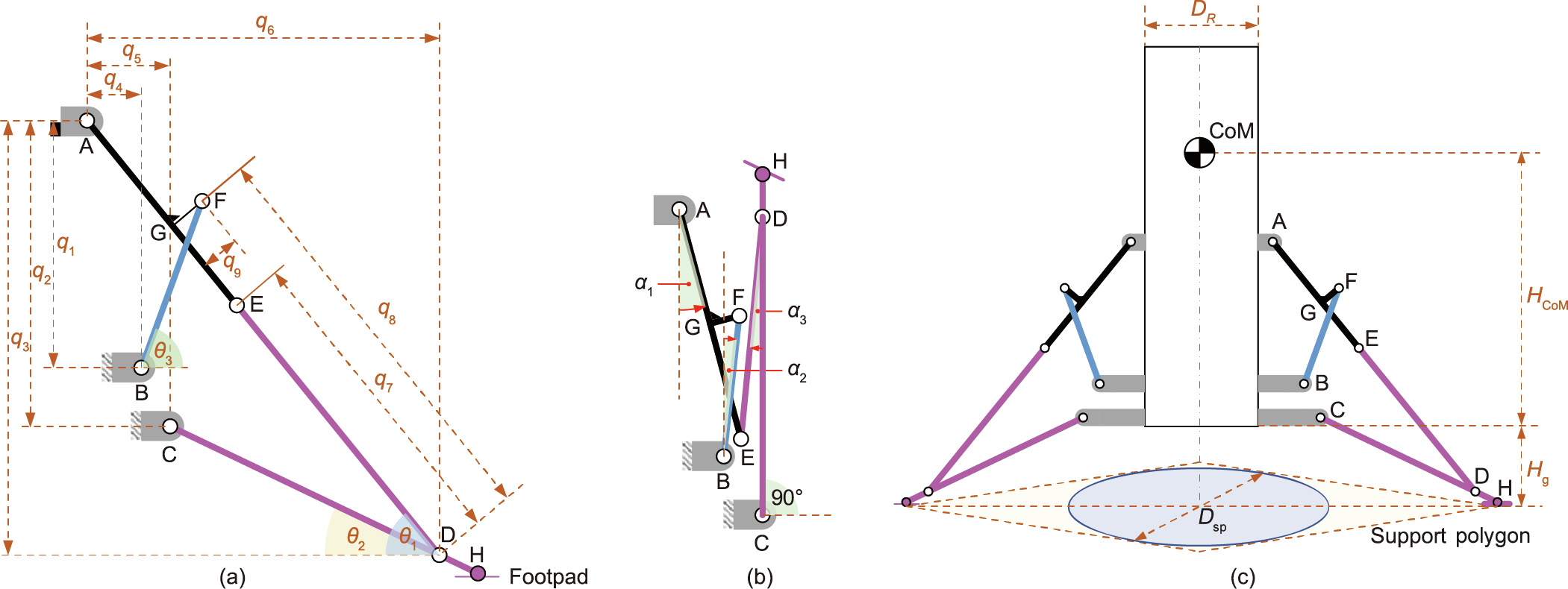
Fig. 5. Parameterization of the preferred topology of the LDLM. (a) Fully deployed; (b) fully folded, the red arrows indicate the positive angular direction for α1–α3; (c) landing support region. CoM: center of mass; A, B, C: ground pivot; D, E, F: moving point; G, H: auxiliary point; α1, α2, α3: vertical dip angle of the link AE, BF, and HE, respectively; h1: tilt angle of the link AD,θ1 = atan2(q3, q6); θ2: tilt angle of the link CH, θ2 = atan2(q3 – q2, q6 – q5); θ3: tilt angle of the link BF, θ3 = atan2(q1 – q3 + q8sinθ1 + q9cosθ1, q6 – q8cosθ1 + q9sinθ1 – q4); DR: diameter of the cabin, DR = 1200 mm; HCoM: CoM height of the cabin, HCoM = 1800 mm; Hg: ground clearance of the fully deployed LDLM, Hg = 1144 mm; Dsp: diameter of the inscribed circle of the support polygon.
3.1.2. Optimization paradigm
The optimization design of the LDLM primarily covers the following targets. Foremost, the LDLM should provide sufficiently large support region to enhance the static stability of the RLV by exploiting the deployable Watt-II mechanism. Second, the overall linkages that constitute the single leg of the LDLM should be lightweight from the perspective of geometric scale by optimally allocating connecting rod lengths of individual linkage components. Finally, the internal forces amongst individual linkages should be suppressed at landing to avoid structural damage from excessive impulsive load. These aforementioned targets were transferred into the scalars of the optimal variables q1–q9 to compose the optimization objective function.
In case of the first target, the support region of the LDLM at landing is quantified by the diameter of the inscribed circle of the support polygon, as shown in Fig. 5(c). According to the geometry relationship, this objective indicator can be expressed in a dimensionless format.
where DR is the diameter of cabin; Dsp is the diameter of inscribed circle of the support polygon; Hg is ground clearance of the fully depolyed LDLM; J1(q) is the objective indicator referring to the static stability of the RLV; LDH is the length bias of the footpad, LDH = 120 mm; LCD is the Euclidean distance between the points C and D, and is expressed as

For the second target, an equivalent mass method [22] that introduces the equivalent linear density of linkage was employed to simplify the complex linkage mass calculation into a planar link length accumulation problem. Assuming that the linkage components are homogeneous and isotropous, the total mass of the Watt-II linkage MWatt can be estimated as
where ρ is the unified equivalent linear density of the linkage; Lj is the length of the jth link in the LDLM; and S is the link family with S = {AD, BF, CD, FG}. In particular, the length  can be directly derived as follows.
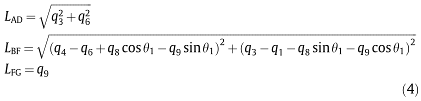
where LAD, LBF, and LFG are the length of link AD, BF, and FG, respectively; θ1 is the tilt angle of the link AD.
Subsequently the dimensionless objective indicator for the second target can be defined as follows:

where MCabin = 634 kg is the cabin mass that was introduced to scale the mass of the Watt-II linkage such that the scalar function (Eq. (5)) was comparable with the other objective functions.
Finally, regarding the third target, a quasi-static force analysis, as shown in Fig. 6, was implemented via the addition of the maximum landing impulsive load at the footpad of the LDLM to determine the internal forces amongst individual linkages. The impulsive load Fadd vertically exerted at footpad is formulated as Fadd = Fmagδ(t) with δ(t) being the standard Dirac-δ function (t is time) and Fmag being the magnitude of the impact. Under a certain level of the impulsive load Fadd, the internal forces amongst individual linkages were conveyed in terms of the pivot net forces, resulting in the sagittal force formulation as below.

where  is the coefficient matrix of the pivot net forces;
  is the vector of the pivot net forces of the LDLM with Fpivot = [FAx, FAy, FBx, FBy, FCx, FCy, FDx, FDy, FEx, FEy, FFx, FFy]T , and
  is the external force vector that collects the gravitational forces and the impulsive load. The expression of the vector D(q) and Q(Fadd, q) are detailed in Part I in Appendix A. The maximum of the impulsive load Fadd can be represented according to International Organization for Standardization (ISO)/ technical specification (TS) 15066 [23] as follows.

where  is the vertical landing velocity of the RLV with = 1.98 m·s–1 (equivalent to freefalling height of 0.20 m); MRLV and Mgnd are the mass of the RLV and the ground, respectively; and kcontact = 2.4 ×10⁵ N·m–1 is the equivalent stiffness between the RLV and the ground. Particularly, Mgnd
  MRLV holds such that
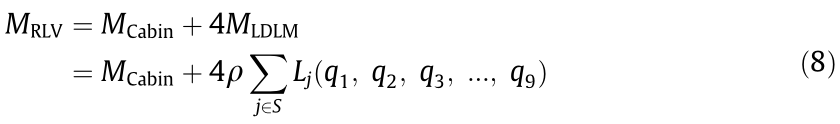
  can be ignored in Eq. (7). Furthermore, MRLV is the mass sum of the cabin and the four LDLMs, and is expressed as
Ultimately, the third objective function that minimizes Fpivot scaled by the cabin weight can be defined as follows:
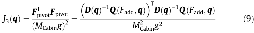
where g = 9.81 m·s–2 is the gravitational acceleration. The nonlinear constraints of the design variables q contain the equality constraint and the inequality constraints. For the former part, the ground clearance of the LDLM as fully deployed should be guaranteed to provide sufficient room for the engine exhaust nozzle (as a scale model from the launch vehicle archetype), which yields

where F(q) is the function for the equality constraint of the optimal variables.
《Fig. 6》
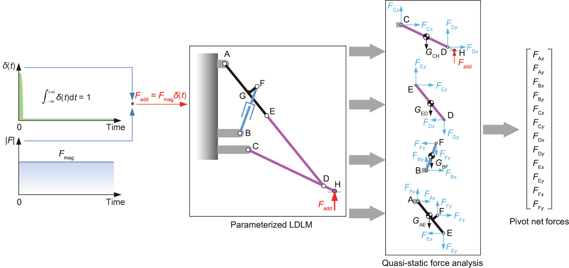
Fig. 6. Schematic of the quasi-static force analysis of the LDLM under a certain level of impulsive load Fadd. δ(t): standard Dirac-δ function and t is time; Fadd: impulsive load; Fmag: the magnitude of the impact; GCH, GED, GBF, GAE: the gravitational force of the link CH, ED, BF and AE, respectively.
For the latter part, three categories of the scale constraints were proposed to shape the Watt-II mechanism.
(1) Linkage length constraints. The linkage lengths of the Watt-II mechanism should be restricted to maintain the feasible configuration, thus generating the boundedness of the key linkage lengths as shown in Table 1.
《Table 1》
Table 1 Boundedness of the key linkage lengths of the Watt-II mechanism.

Rewriting the bilateral boundedness condition in Table 1 to derive the following nonlinear constraints in Eq. (11).
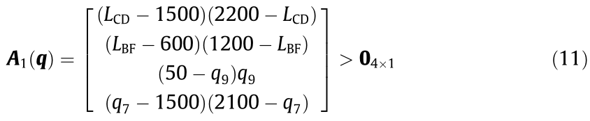
where A1(q) is the matrix for the bilateral constrains of the linkage lengths; LCD and LBF can be directly calculated using Eqs. (2) and (4).
(2) Linkage control point constraints. The linkage control points A–G should satisfy q8 > q7 > q9, q6 > q5 > q4, and q3 > q2 > q1 simultaneously, which can be reformed as follows.

where  is the coefficient matrix (detailed expression in Part I in Appendix A).
(3) Auxiliary angle constraints. At fully folded configuration, the auxiliary angles α1, α2, and α3 should be positive such that the LDLM can be deployed successfully without blocking, which leads to the following constraints.

where the intermediate variable σ is provided in Part I in Appendix A. Thus, by combining the multi-objective functions (Eqs. (1), (5), and (9)) and the nonlinear constraints (Eqs. (11)–(13)), the optimization paradigm can be formally constructed as

where A(q) is the composite matrix for the nonlinear inequality constraints with A(q)=[A1, A2, A3] T .
3.1.3. Main result
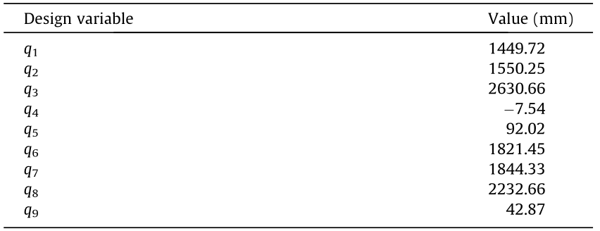
To solve the optimization problem Eq. (14), the NSGA-II evolutionary algorithm [24] was implemented on a personal computer (PC) (Intel core i7 processor of 3.2 GHz, 32 GB of random access memory (RAM)) to seek the Pareto-optimal front [25]. The values of the population size, Pareto fraction, and generation were set at 250, 0.3, and 300, respectively. The result of the non-dominated solutions with the Pareto-optimal set of 29 are shown in Fig. 7. On observing the tendency of the Pareto front set in Figs. 7(a)–(c), it is evident that the relationships between the objective function J1 and J2, J1 and J3 are contradicting to each other, Therefore, a trade-off preference amongst the static stability, lightweight, and linkage internal forces should be made. Upon determining the Pareto-optimal set, it is conventionally required to select the best compromise solution for further implementation.
《Fig. 7》
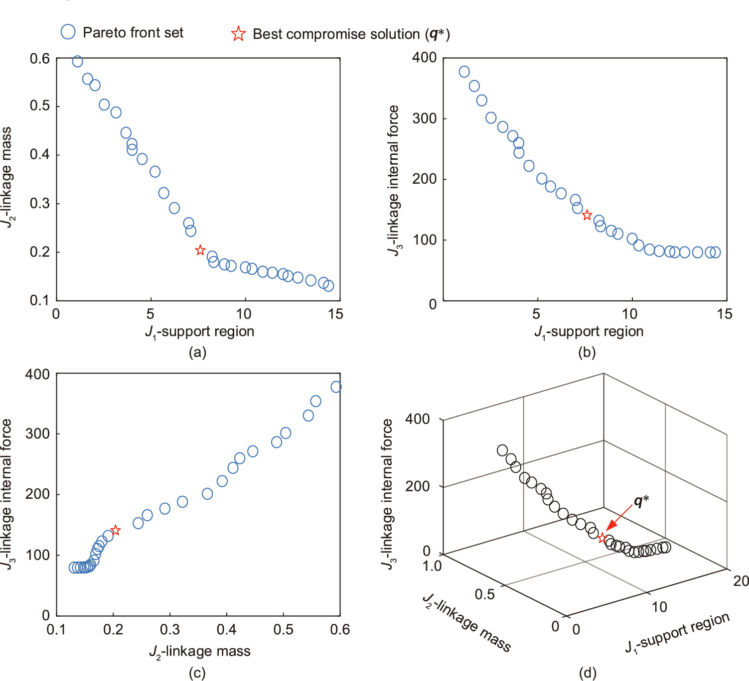
Fig. 7. Pareto-optimal set with NSGA-II in two- and three-dimensional objective space for the optimization problem (Eq. (14)). Red star indicates the best compromise solution obtained using TOPSIS method. (a–c) Two-dimensional objective space of J1 vs J2, J1 versus J3, and J2 versus J3, respectively; (d) three-dimensional objective space of J1, J2, and J3.
Herein, the technique for order preference by similarity to an ideal solution (TOPSIS) approach [26] was employed without recourse to additional experts’ knowledge, to find the best compromise solution to the optimization problem (Eq. (14)). Shannon’s entropy metric [27] was adopted to rank individual NSGA-II solutions based on comparisons of the relative closeness to the ideal solution. Consequently, the optimal parameter q* as the best compromise solution against the finite set of 29 Pareto-optimal solutions was obtained (further details on ranking procedure in Part II in Appendix A). Finally, q* presented in Table 2 was utilized as the reference length parameters for the physical design and fabrication of the LDLM.
《Table 2》
Table 2 Optimization results of the design variables of the LDLM.
《3.2. Gravity-governed deploying scheme》
3.2. Gravity-governed deploying scheme
Owing to its mechanical simplicity and durability, the pneumatic-driven system was equipped to trigger the LDLM from the fully folded position as mentioned in Section 2.2. As illustrated in Fig. 8, four air cylinders (AirTAC SC-50-200-S) were manipulated via the flow control valves (AirTAC PSL802A) with a unified synchronization command that enabled the solenoid valves (AirTAC 4V2108B). In practice, the input air pressure is set at 0.6 MPa to provide a neat shoot of each cylinder, thus propelling each LDLM at the bursting speed of 0.5 m·s–1 to release from the initial positioning locker. Furthermore, the power consumption for single pneumatic trigger system was approximately 753.98 W for the initial push of each LDLM. Immediately following the release of the initial locker, the LDLM exhibited passive gravity-governed deploying behavior. Moreover, the center of mass (CoM) of the LDLM at fully folded configuration was located anterolateral to the main pivot C such that a slight deviation of the CoM subsequently incurred falling to facilitate unfolding action.
《Fig. 8》
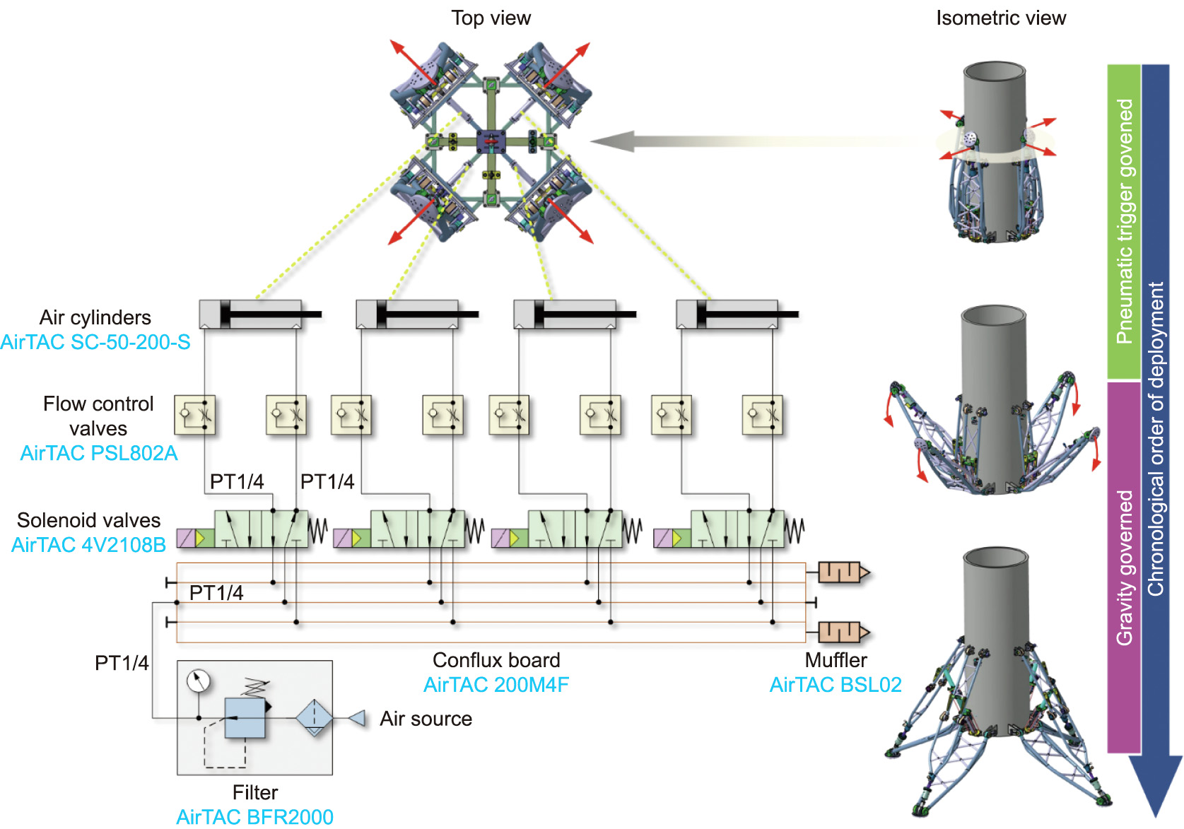
Fig. 8. Schematic of the pneumatic trigger system. PT1/4: pipe thread size of 1/4 in (1 in = 2.54 cm).
《3.3. SA with multistage honeycomb》
3.3. SA with multistage honeycomb
The main challenge of devising an SA is the manner in which to absorb sufficient energy with preferred structure or deformable material in a condensed cavity. To this end, a crushing-type SA with multistage aluminum honeycomb core was adopted in this scenario. The basic composition of the SA is shown in Fig. 9, where the specimen details of customized honeycomb cores are presented. The dummy plate located in–between the primary and secondary honeycomb cores divided the inner cavity into disconnected parts, thereby providing a smooth crush to the secondary honeycomb core while the push rod compressed the primary honeycomb core. Seeking the worst landing condition is crucial for devising an SA. Considering the worst landing condition that a single leg touches the ground to absorb impact ahead of other legs, the maximum estimate of the overall energy (OE) can be calculated by combining the kinetic energy of the system at landing-instant and the gravitational potential energy from the CoM position variation of the RLV caused by the length shortening of SA, which implies.

where EOE = 1.8 ×10³ J is the maximum estimate of the energy to be absorbed for single-leg in the worst landing condition; MRLV = 1.12 ×10³ kg is the total mass of the RLV;  = 1.98 m·s–1 is the landing velocity of the RLV’s CoM (equivalent to freefalling height of 0.2 m);
  = 132 mm is the maximal permissible descent height of the RLV’s CoM caused by the length shortening of SA; μ is the scale factor of the absorbed energy for single-leg, and μ = 0.5 indicates that 50% of EOE ought to be absorbed by the SA of the single-leg first to contact ground.
《Fig. 9》
Fig. 9. Structure of the SA unit with multistage aluminum honeycomb cores.
To fulfill the energy absorption requirement of EOE and provide a smooth landing behavior with attenuated peak acceleration of the RLV’s CoM, the parameters of the primary and secondary honeycomb cores were elaborately devised with the specifications presented in Table 3. Moreover, to reveal the mechanical properties of the applied material in the SA, both the simulation and experiment were conducted, and the results are shown in Fig. 10. In the simulation, a finite element analysis (FEA) of the prescribed aluminum hexagonal honeycombs was employed in ANSYS/LSDYNA. In the physical experiment, the customized honeycomb specimen was fabricated and placed on the Instron Universal Tester (5969, Instron, USA) to conduct bare and stabilized compressive tests.
《Table 3》
Table 3 Specifications of the multistage aluminum honeycomb cores.

《Fig. 10》
Fig. 10. Experimental and finite element analysis (FEA) simulation results of the multistage aluminum honeycomb core. (a) FEA simulation and physical test; (b) mechanical properties.
Similar deformation patterns of the honeycombs were observed in both the FEA and experimental results, as shown in Fig. 10(a). Furthermore, similar tendency of the stroke distance–crush force curves was observed when comparing the simulation and experiment results in Fig. 10(b). The crush plateaus were exhibited in both primary and secondary honeycomb, which provided stable and smooth reaction force of the SA. The statistical representations for the crush plateaus in physical test were (6.38 ± 0.35) and (10.90 ± 0.15) kN for the primary and secondary honeycombs, respectively. According to the partition of the energy absorber zone, the valid energy absorbed by the multistage honeycomb cores was over 1822 J, which implies that the customized SA satisfies the energy absorption requirement against the worst landing condition. In addition, the initial peak force that emerged in the elastic deformation stage from Fig. 10(b) was observed in both the primary and secondary honeycomb and should be eliminated to prevent exacerbation of impact effect. In practice, the pre-compression treatment is enforced for all the honeycomb specimens before they can be mounted inside the sleeve of the SA, thus offering ameliorative plateau behavior of mechanical performance.
《4. Experiments and results》
4. Experiments and results
《4.1. Experiment setup》
4.1. Experiment setup
The arrangement of the experiments is shown in Fig. 11. To verify the functionality and performance of the devised LDLM for the RLV, deployment and soft-landing tests were conducted with multi-sensory sampling. The detailed information of the sensors adopted in the experiments are described in Table 4. The central computer combined with the auxiliary data acquisition (DAQ) system control the releaser triggering, system monitoring, and sensor sampling task.
《Fig. 11》
Fig. 11. Experimental setup for the RLV prototype with key sensors. Dist.: distance; DAQ: data acquisition; IMU: inertial measurement unit.
《Table 4》
Table 4 Sensors adopted in the experiments.
《4.2. Deployment test》
4.2. Deployment test
In this scenario, the RLV was overhung vertically with the LDLM fully folded and the initial locker engaged. When simultaneously triggered by the pneumatic cylinders, the LDLMs began to execute deploying action, as indicated by the recorded snapshots shown in Fig. 12. In general, four LDLMs were successfully deployed following their release from the initial locker. When the individual legs reached the bottom extreme position, as illustrated in Fig. 3, the locking mechanism of each LDLM was completely engaged, thereby providing reliable support to stiffening the deployable mechanism into firm structure for landing.
《Fig. 12》
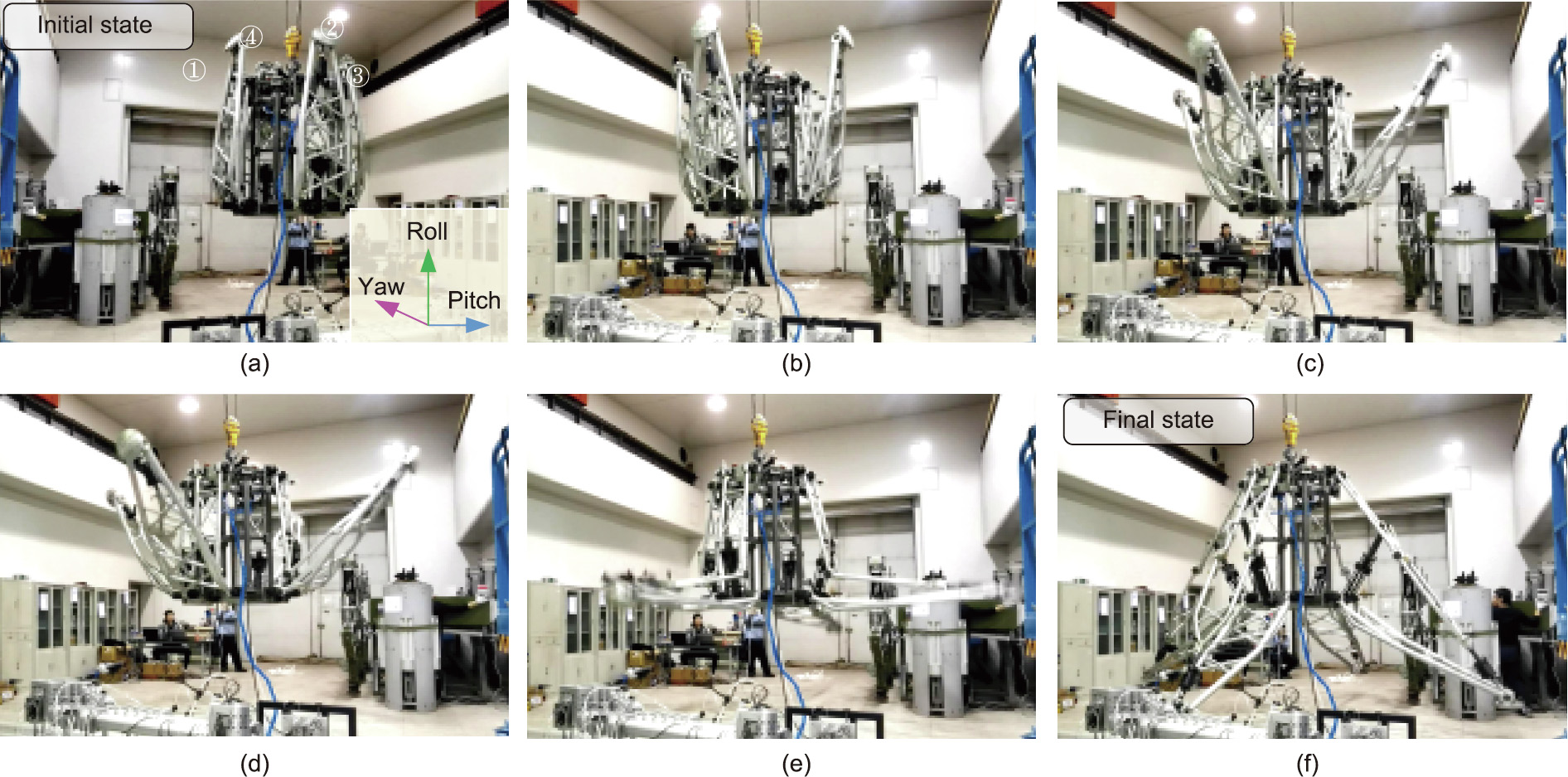
Fig. 12. Snapshots of the deploying process of the LDLMs from static overhead hanging. Initial and final states are highlighted in blue and yellow for clarity, respectively. Recorded time t is (a) t = 0 s; (b) t = 0.41 s; (c) t = 0.62 s; (d) t = 0.75 s; (e) t = 0.89 s; (f) t = 1.20 s. Numbers in (a) indicate the labels of the corresponding LDLMs, inset image illustrates the orientation of the cabin body.
To further investigate the deploying performance of the LDLMs, the joint movements of the key pivots from four LDLMs are plotted in Fig. 13(a), which indicates the actual deploying process of each leg. The time occupation for deploying was roughly less than 1.5 s. It is evident that the four LDLMs governed by gravitational forces exhibited synchronized movements at the deploying stage. By observing the peak stroke of each LDLM (partial view in Fig. 13(a)), the maximum time delay of individual legs approaching the fully deployed state was found to be 0.052 s and it occurred between the diagonal pairs LDLM1 and LDLM3. The main reason for these slightly inconsistent actions is that there exists certain discrepancy of dynamic properties amongst individual legs owing to fabrication and assembly errors, which cannot be self-adjusted by the leg gravitational forces themselves during deployment. This phenomenon can be ameliorated by further introducing semi-active control to manipulate the movement of each LDLM with compensation on the inconsistency of dynamic characteristics.
Fig. 13(b) also shows the posture angles of the cabin body during the deployment test. According to the recorded data of the applied IMU at sampling rate of 500 Hz, the largest fluctuation values in pitch and yaw angles in the deploying stage are 0.46° and 0.55°, respectively; however, they reached 5.72° and 3.94°, respectively, throughout the tests. This increase in the posture angles after the fully deployed state was caused by the residual waggle around the hanging point and was gradually attenuated as the RLV restored stability. Thus, endowing the advantages of high deployed/folded ratio and large landing support region, the devised LDLM displayed smooth deploying movement without inducing remarkable posture disturbance to the cabin body, which benefits the attitude control of the real RLV when approaching to landing.
《Fig. 13》

Fig. 13. Experimental results of the deployment test for the LDLM. (a) Joint angle of the pivot A; (b) posture angles of the cabin body. Fully folded, deploying, and fully deployed regions are highlighted in grey, green, and yellow, respectively.
《4.3. Soft-landing test》
4.3. Soft-landing test
In this scenario, the RLV connected by the wireless releaser was vertically hanged with a ground clearance of 200 mm (equivalent to a landing speed of 1.98 m·s–1 ). When the wireless command triggered the releaser, the RLV experienced free fall, with the snapshots of the soft-landing shown in Fig. 14. In the test, the accelerometers were distributed and arranged on the footpad, cabin bottom section, geometry center (GC), and apex to synchronously measure the overload acceleration of the RLV. They shared a comprehensive view of the routine that the landing impact traversed. As shown in Fig. 15(a), the landing impact at the footpad approached 75.20g (737.71 m·s–2 ) when the RLV touched the ground. However, after experiencing the buffering from individual SAs, the peak value dramatically reduced to 14.51g (142.34 m·s–2 ) and 9.38g (92.02 m·s–2 ) at the cabin bottom and the GC, respectively. This indicates that the devised SA with multistage aluminum honeycomb cores effectively absorbed the impact energy, providing guaranteed safe condition for the RLV at landing.
《Fig. 14》
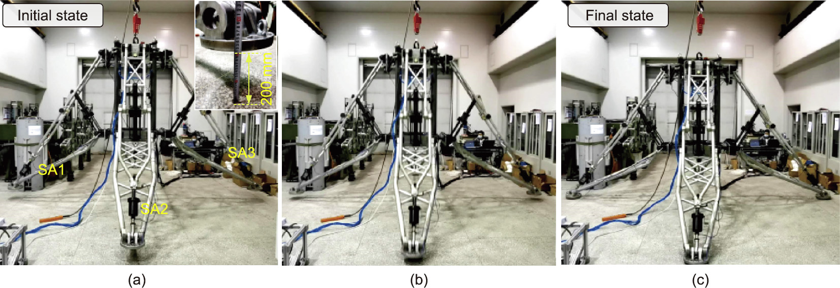
Fig. 14. Snapshots of the soft-landing process of the RLV. (a) t = 0 s; (b) t = 0.13 s; (c) t = 0.20 s. Inset image in (a) shows the ground clearance (200 mm) with respect to the footpad and numbers indicate the labels of the corresponding SAs.
《Fig. 15》
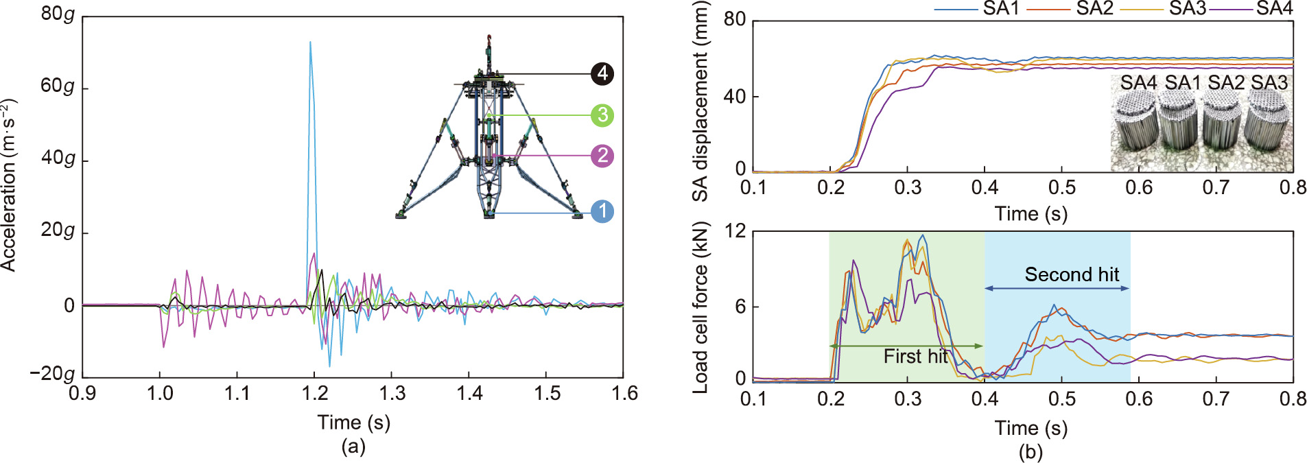
Fig. 15. Soft-landing test results of the RLV with the multistage aluminum honeycomb cores. (a) Overload accelerations measured via distributed accelerometers on the RLV; (b) SA displacement and load cell force data for four legs throughout the test. Inset image shows the final shapes of the cores after landing. Regions corresponding first hit and rebound are shaded in green and blue, respectively.
According to the sampled data from the laser distance sensors and the corresponding load cells, the SA displacements and crush forces of four LDLMs are shown in Fig. 15(b). Similar plateau stages were observed in the SA1, SA2, and SA3, which is consistent with the mechanical properties mentioned in Section 3.3. Furthermore, the SA displacements also revealed the landing sequence of four legs. However, SA4 maintained the crush plateau-I stage at the first hit region rather than experiencing dual-plateau stages as observed in the SA1–SA3, implying that the primary energy was absorbed by the anterior legs before the SA4 entered the plateauII stage. Moreover, the second hit of all four legs were observed to handle the residual impact effect (approximately 21% of the OE at landing). Fig. 16 shows the deformation results of individual honeycomb cores with pre-compression amounts of 4.68 mm (6.5% of the original thickness) and 6.25 mm (5% of the original thickness) for the primary and secondary stage, respectively. Thus, the proposed multistage honeycomb scheme rapidly suppressed the early landing impact using the primary honeycomb with relatively low crush plateau, and subsequently absorbed a large proportion of the landing energy using both the primary and secondary honeycombs. Furthermore, the experimental results confirmed that the devised SA could provide satisfactory buffering performance for the RLV at landing.
《Fig. 16》
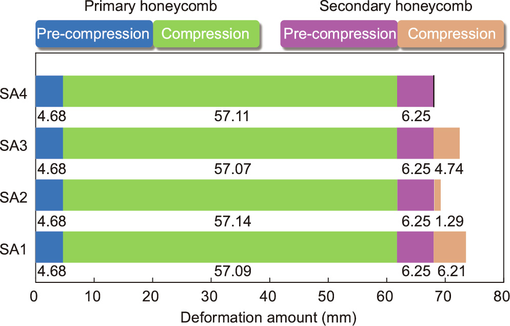
Fig. 16. Extent of deformation of individual honeycomb cores in the soft-landing test. Pre-compression treatment is applied for both primary and secondary honeycombs in each SA.
《5. Discussion》
5. Discussion
The experimental results demonstrated that the developed LDLM can display rapid and smooth deploying with mild posture fluctuation and effectively attenuating landing impact. This is a result of the unique landing mechanism working in conjunction with the proposed the gravity-governed deploying scheme and the multistage honeycomb-based SA. In contrast to the existing landing gears adopting telescopic (Falcon-9) and parallel (New Shepard) configuration, the most conspicuous feature of the developed LDLM is the optimized Watt-II six-bar configuration that offers advantages of large landing support region, lightweight, and reasonable linkage internal forces. Moreover, the merits of the proposed deploying scheme were twofold. First, only a slight pneumatic initial push is required to trigger the LDLM instead of high-pressure helium resource. Second, it avoids full-range hydraulic/pneumatic actuation, thus exhibiting gravity-governed passive unfolding behavior to facilitate deploying process.
However, substantial studies need to be conducted to further improve the performance and practicability of the proposed LDLM to achieve integration with full-sized RLV. First, the performance consistency issue between the developed scaled LDLM prototype and the full-sized archetype should be considered. The optimized Watt-II configuration is more complicated in structural style than the existing telescopic and parallel mechanisms. This phenomenon will be reflected and amplified in the mass/inertial specifications of the landing gears in full-sized archetype wherein lightweight highstrength material with well-behaved mechanical property is anticipated to fabricate landing gears. However, considering that various materials utilized in fabrication might violates the homogeneous assumption in Eq. (3), the mass estimation Mwatt can be thereby altered using linear density-weighted cumulative sum of linkage length to update the original optimization paradigm. In addition, the deploying duration measured in Section 4.2, wherein the cabin was statically suspended, may change when applying on the full-sized RLV at descent stage owing to the scale effect and cabin state discrepancy.
Second, the successful implementation of the gravity-governed deploying is dependent on repeatable unfolding smoothness of individual hinge joints in the devised LDLM. Any stuck or retardant motion in rotatory/prismatic joints will directly deteriorate the deploying process or even lead to failure. For the selected Watt-II six-bar mechanism with rich hinge joints, such non-smooth behavior is more likely to emerge in prismatic joints, such as the cylinder-type kinematic pair adopted in the devised locking mechanism in Fig. 2(b) particularly applied on the full-sized archetype. From a practical perspective, self-lubricating antifriction material with thermal protection arrangement is a potential solution in fabricating rotary joints to enhance unfolding smoothness and reliability of the LDLM executing deploying action. Furthermore, the lightweight sliding mechanism with radial ancillary shoring can be integrated into the telescopic locking mechanism to improve bending strength and axial guidance of the cylinder-type kinematic pair provided that the space occupation is permitted.
Third, the passivity nature of the developed landing gear when displaying gravity-governed deploying is an intrinsic limitation to achieving strict synchronization amongst four LDLMs. Owing to lack of coordination tools from both mechanical system and control approach, the inevitable asynchronization induced by initial pneumatic push and dynamics discrepancy of individual LDLMs cannot be overcome and compensated for in such a scenario. This problem can be mitigated as follows. On the mechanical level, compact coupling synchronizer unit can be mounted inside the cabin to passively coordinate the deploying process of the four LDLMs. On the control level, a synchronization control strategy with semi-active adjustable damper can be implemented to fulfill closed-loop deploying control for the LDLMs.
Finally, the reliability and maintainability of the developed LDLM should be further improved before it can be adopted in full-sized RLV archetype. Although the key performances including deployment and shock absorption have been experimentally validated, further investigation considering wear, corrosion, fatigue, and mechanism degradation is required. Systematic evaluations over critical failure modes, causes of unreliability as well as recyclability that help to reveal the serviceability limit of the proposed LDLM in future applications must be provided.
《6. Conclusions and future work》
6. Conclusions and future work
In this study, a novel LDLM for RLV was proposed. Adopting the Watt-II six-bar mechanism as the fundamental configuration template, the LDLM was devised using multi-objective optimization including landing support region, lightweight, and linkage internal forces. In addition, a fully-functional scaled prototype featuring gravity-governed deploying, dual-backup locking, and multistage shock absorbing was fabricated. The experimental results demonstrated that the devised LDLM can achieve rapid and smooth deployment (duration and posture fluctuation less than 1.5 s and 6°, respectively) while exhibiting satisfactory landing impact attenuation with an acceleration peak less than 10g in the 0.2 m freefall landing test. In a future study, the current optimization approach will be extended from planar linkages to spatial linkage group, offering numerous configurations of deployable mechanisms with more favorable intrinsic properties. Further, active deploying control to generate synchronized unfolding action that minimizes momentum disturbance to the posture stability of RLV will be focused upon. Finally, the reliability and maintainability of the proposed LDLM should be systematically evaluated and improved to enhance applicability in future RLV archetype.
《Compliance with ethics guidelines》
Compliance with ethics guidelines
Haitao Yu, Baolin Tian, Zhen Yan, Haibo Gao, Hongjian Zhang, Huiqiang Wu, Yingchao Wang, Yuhong Shi, and Zongquan Deng declare that they have no conflict of interest or financial conflicts to disclose.
《Appendix A. Supplementary data》
Appendix A. Supplementary data
Supplementary data to this article can be found online at https://doi.org/10.1016/j.eng.2022.05.015.


 京公网安备 11010502051620号


