
《1. Introduction》
1. Introduction
Residual stress is a fundamental property of materials [1], and the distribution of residual stress within materials can be represented as residual stress fields. The residual stress field affects the material strength [2], machining accuracy, geometric and dimensional stability, fatigue life [3], and natural aging deformation [4] of a part. Therefore, it is important to analyze residual stress field in the design, manufacture, and service processes of high-value products in fields such as the aerospace and nuclear industries, where parts are large and extremely costly, and have complex functions [5]. To meet the performance and safety requirements for high-value products and/or equipment, measuring the residual stress field of large parts with high accuracy while leaving the parts undamaged is an indispensable step in the manufacturing process [6]. The manufacturing quality of large structural parts for aerospace products, especially the final accuracy in terms of size, form, and position, faces great challenges due to an inability to accurately measure or predict the residual stress field. Moreover, it is difficult to ensure the assembly state of components. Therefore, the designed comprehensive performance of the products—such as dynamic performance, fatigue life, and stealth—cannot be guaranteed.
《1.1. Existing methods and technologies》
1.1. Existing methods and technologies
Many residual stress measurement methods and technologies have been proposed and developed; these can be divided into two approaches: destructive and non-destructive methods. In destructive methods, residual stress is calculated by measuring the strain in a local area caused by the released residual stress of the destructed material. The local destruction of the material is realized by cutting holes [7], slits [8], contours [9], and surfaces [10] on different layers of the material, as shown in Fig. 1(a). Therefore, to measure the residual stress field, the whole workpiece must be destructed. Moreover, the stress-releasing process for the measurement of strain leads to stress redistribution and error accumulation.
《Fig. 1》
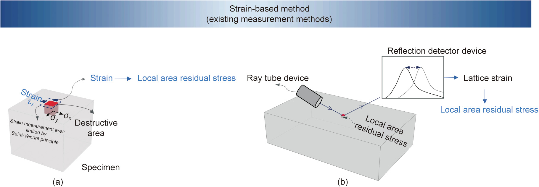
Fig. 1. Examples of existing strain-based methods. (a) Destructive methods; (b) non-destructive methods. εx: strain in x direction; σx: residual stress in x direction; σy: residual stress in y direction.
To avoid damaging the workpiece, non-destructive methods measure properties influenced by strain without destructing the material, by means such as the diffraction measurement method, thermoelastic residual stress measurement method [11], and indentation method [12]. However, these methods also have limitations due to the large quantity and low efficiency of measurements. For example, the X-ray diffraction method [13] is widely used in industry [14–16], but it can only measure the residual stress on the workpiece surface, as shown in Fig. 1(b). The neutron diffraction [17] and synchrotron radiation methods [18], which have powerful penetration depth, hold potential to measure residual stress fields without damaging the workpiece. However, they require highly specialized and complex equipment [19], and great improvement is needed in their measurement efficiency and accuracy for industrial applications. Normally, the residual stress is calculated based on changes in the lattice strain in comparison with a ‘‘zero stress” reference sample. The measurement accuracy of nondestructive methods is affected by the ‘‘zero stress” reference sample, which is difficult to realize. Furthermore, diffraction methods have a high measurement error for metal materials with textures, such as aluminum alloys and titanium alloys, which can result in a measurement difference as high as 50 MPa or even 100 MPa compared with destructive methods [20].
Existing methods are ‘‘strain-based;” that is, their purpose is to measure the strain in order to calculate residual stress. However, according to Saint-Venant’s principle [21], the load only has an effect on the generated stress distribution near the force action area; thus, only the strain near the measurement area can be measured for calculating the residual stress. Therefore, it is inevitably necessary to measure the local residual stress at numerous points in order to construct the residual stress field, which results in low accuracy due to the destruction of the whole workpiece in destructive methods, or, in non-destructive methods, requires highly specialized and complex equipment and a measuring time that extends over days and weeks [8]. To sum up, existing residual stress measurement methods have the following main disadvantages: the strain measurement areas are limited by SaintVenant’s principle; the parts being measured are destroyed; and the measurement efficiency is low. With increased product function and quality requirements, and in more digitalized intelligent manufacturing systems, new challenges are added to internal residual stress field measurement and prediction, including the following:
(1) High accuracy and resolution. High measurement accuracy and resolution of the residual stress field are required. Especially for large parts, a rough estimation of the distribution of the residual stress field can no longer meet the needs of precision manufacturing. Thus, residual stress values must be obtained in more areas of the part.
(2) Avoiding damage to the part. Due to the high cost of large and high-precision parts, it is necessary to infer or measure the residual stress field of every part without damaging the part.
Therefore, existing measurement methods cannot satisfy the requirements of high-quality process control in the context of digital and intelligent manufacturing, due to their low efficiency and accuracy.
《1.2. The proposed deformation-force-based non-destructive method》
1.2. The proposed deformation-force-based non-destructive method
In the material removal process, an unbalanced residual stress field is characterized by the changes in forces at the fixturing and clamping points (or surfaces), which are defined as deformation forces, as illustrated in Fig. 2. Thus, we propose a new idea for inferencing the residual stress field: using a deformation-forcebased residual stress field inference method via an established mechanical model based on the principle of virtual work. Compared with the hole-drilling destructive method, the prediction error of the validation index is reduced by 86.2% for the case of aluminum alloy structural parts used in aircraft, which satisfies the strict requirements guiding the process optimization of highprecision part machining.
《Fig. 2》

Fig. 2. The proposed deformation-force-based method for inferencing the residual stress field. M: global volume coefficient matrix; σ0: residual stress vector;  : deformation forces;
  : inferenced residual stress;
  : optimized parameter; K: regularization matrix;
  : measured deformation forces;
  : deformation force of first fixture in x, y, and z direction, respectively;
  : deformation force of second fixture in x, y, and z direction, respectively.
In this study, it is possible to monitor and obtain the deformation forces of a part during the normal manufacturing process as planned, without the need to carry out separate measurements. In contrast, in existing methods, it either is necessary to damage a part in order to measure the residual stress in different points within the part, or takes a very long time to measure and requires highly specialized equipment. Another advantage of the proposed method is that the deformation forces can be monitored after each material removal process while the workpiece is still fixtured and clamped, which provides the possibility of inferencing the in situ residual stress field of the workpiece in its initial and aftermachining states. The residual stress of each workpiece can be inferred with flexible resolution as required, with high accuracy, and with no unnecessary damage of parts, which is important for the manufacturing of large and high-requirement parts and lays a foundation for high-quality process control in modern industries.
《2. Mechanical mechanism of the deformation-force-based residual stress inferencing method》
2. Mechanical mechanism of the deformation-force-based residual stress inferencing method
《2.1. Mechanical relationship between the deformation forces and the workpiece residual stress field》
2.1. Mechanical relationship between the deformation forces and the workpiece residual stress field
An unbalanced residual stress field in a workpiece will cause workpiece deformation after each material removal process. Deformation force is defined as a group of surface forces, and is equivalent to the influence of the residual stress field on deformation [22]. In an actual manufacturing environment, the finite deformation force can be obtained by measuring the changes in the reactions at all the constraint points in the x, y, and z directions on the part that are caused by the changes in the residual stress field after the material removal process when the workpiece is still fixtured and clamped, as illustrated in Fig. 2. It should be noted that this method is under the assumption of linear elasticity. Moreover, the local deformation of the material should remain unchanged or be negligible during the material removal process by the constraint system (fixtures), in order to ensure that the residual stress field of the remaining material remains unchanged after the material removal process. Under these conditions, the layout of the constraint points for measuring the deformation forces does not affect the results of the inferred residual stress field.
A workpiece (that is still fixtured and clamped after machining) containing both the reactions of the deformation forces and an unbalanced residual stress field is in an equilibrium state. According to the principle of virtual work, the work done by the external force—that is, the deformation force—on the virtual displacement is equal to the work done by the internal force—that is, the residual stress field—on the virtual displacement. The equilibrium equation considering the volume force can be represented as follows:

where  is the virtual displacement of the element nodal;
  is the lth deformation force conducted in the element nodal;
  is the virtual strain of the element;
  is the stress of the element, which is subtracted by generated stress
  and residual stress
  ; g is the volume force; Vn is the geometric state after the nth material removal process; and Ve is the element volume.
The virtual strain  satisfies
  , where
  is the element geometry matrix. This equation transforms the virtual strain into the virtual displacement. Therefore,

Furthermore, the equilibrium equation of the deformation forces and the residual stress is

where  is the volume matrix of geometry Vn and
  , in which
  represents the extent of the influnce of the stress of an element on a particular element node);
  is the residual stress vector;
  is the system stress vector;
  is the element nodal force vector added by influence of the residual stress field and the volume force, according to the linear superposition principle, and is composed of the deformation force of the monitored node and the zero value of the non-monitored node.
《2.2. A residual stress field inferencing method based on deformation forces》
2.2. A residual stress field inferencing method based on deformation forces
Eq. (3) represents the relationship under a geometric state with a limited number of deformation forces and a large number of in the residual stress field. By considering the boundary conditions and ingoring volume force,  can be eliminated to get
  . To infer the residual stress field, enough deformation force equations can be established, based on the geometric changes caused by material removal from the workpiece in the actual manufacturing process, which forms a global equation with a total number of
  geometric states:

where M is the global volume coefficient matrix, with M = [M1 , M2 , …,  ] T ; and
  is the deformation force vector measured of all the constraint points in all the machined geometry states, with =
  . In the volume coefficient matrix M,
  refers to the influence of
  the ith residual stress in
  , on deformation force
  in geometric state ; it is decided by the eometry and constraints, and does not change with the value of
  It could can be obtained by using the finite finite-element method, considering the boundary conditions.
Eq. (4) establishes the relationship between the residual stress field and the deformation forces measured during the whole material removal process. The influence of the residual stress field distribution on the deformation force in complex geometry can be considered to be the result of the integral of the stress effect in different areas. This makes it possible to infer the residual stress field of the remaining material areas by removing some of the material areas during the part machining process and to infer the residual stress field for large parts with no additional material damage.
Inferencing the residual stress field is an inverse problem, and the volume coefficient matrix M is an ill-conditioned matrix, which is influenced by the part geometry and the measurement position of the deformation forces. When the deformation forces measured with the noise, as illustrated in Eq. (5), the accuracy of the residual stress field solution will be influenced.
To address this issue, an enforced regularization method based on Tikhonov regularization (TR) using the proposed regularization matrix is used to solve the equation by constraining the magnitude and stability of the solution. The generalized cross-validation (GCV) method is used to select the appropriate regularization parameter, as shown in Eqs. (6) and (7).

where  is measured deformation force;
  is the measurement noise of the deformation force;
  is the optimized parameter; I is identity matrix; and
  is the obtained solution of the residual stress field. K is the proposed regularization matrix according to the prior distribution of the residual stress field, where
  is the element depth of qth reisudal stress
  in the workpiece and kqq is the element of K. The regularization matrix adjusts the variance and bias of the inference, improving the stability of the inference and reducing the lower bound of the error. Tr refers to the trace of the matrix.
  is the replacement of M –1 .
In theory, if there are enough deformation forces, the residual stress of each element could be calculated, resulting in high resolution. However, the number of measured deformation forces is limited by the workpiece material removal process. Thus, a feasible way of calculating residual stress by limited deformation forces data is to make reasonable assumptions or introduce prior knowledge regarding the distribution of the residual stress field according to the actual machining environment.
In summary, the workpiece requiring an inferenced residual stress field is constrained by the constraint system (i.e., the fixtures), where the local deformation of the workpiece should remain unchanged during the material removal process. Then, with the material removal processes, the unbalanced residual stress field causes action forces on the constraint points, generating deformation forces in different geometric states. According to the material removal processes and boundary conditions, the volume coefficient matrix M is obtained. Finally, the residual stress field can be calculated by means of the enforced regularization method.
《3. Validation and results》
3. Validation and results
The proposed method was theoretically verified and then validated using the actual experimental environment. A typical aviation structural part (i.e., a long beam part with complex geometries) made of aluminum alloy was used as the workpiece for validation. The part size was 640 mm × 180 mm × 25 mm. Its residual stress field was divided into 52 areas by merging some volume coefficients of the elements, considering the number of measured deformation forces and the distribution pattern of residual stress field. This improves the resolution of residual stress field inference in comparison with the resolution of traditional residual stress measurement methods for large parts. The material of the part was 7075-T6 aluminum alloy. The Young’s modulus of the material was 71.7 GPa, and the Poisson’s ratio was 0.3. The residual stress field was divided into 52 areas—that is, four areas in each x– y plane and 13 layers in the z direction, as illustrated in Figs. 3(a) and (b). In the z direction, the depth of layers 1–12 was 2 mm, and the depth of layer 13 was 1 mm. Each area contains residual stress in x direction (σx) and residual stress in y direction (σy); the residual stress in z direction (σz) and shear stress could be ignored in this pre-stretching aluminum alloy material, as illustrated in Fig. 3(a). Therefore, the residual stress field was a combination of 104 residual stress values distributed in the 52 areas. The part was constrained by three fixed fixtures and four deformation force monitoring fixtures, with force sensors in the z direction, considering the main deformation force direction of the part material. According to the requirement of the machining process, the three fixed fixtures were used to constrain the six degrees of freedom of the part to ensure the machining locating criterion, as illustrated in Figs. 3(a) and (b).
《Fig. 3》

Fig. 3. Details of the experimental environment. (a) Illustration of the aircraft part divided into seven pockets and 11 layers of material removal (later, layers 12 and 13 were the remaining material); (b) the part divided into four areas of residual stress field in the actual experiment, fixtured and clamped with force sensors ready for machining.
The material of the seven pockets on the part, which are indicated as A, B, C, D, E, F, and G in Fig. 3(a), was machined to 22 mm in depth, and the depth of cut of each machining operation (i.e., each layer) was 2 mm; thus, 11 layers of material were removed. The 12th and 13th layers were the remaining material. Therefore, in total, 77 material removal operations were carried out for the seven pockets. In this experiment, the material removal method was milling, and the strategy used in the material removal method was ‘‘layer priority,” which means that the material at the same depth (i.e., in the same layer) in different pockets was removed sequentially before machining the material in the pockets at the next layer. The material removal sequence of the seven pockets in the same layer is illustrated in Fig. 3(a) from A to G. For each layer of material removed from one pocket, four deformation forces were obtained by the four sensors installed in the four clamping positions. Thus, 308 deformation forces were obtained during the experiment, which were generated in the four force sensors during 77 material removal operations. The scale of the full volume coefficient matrix M11 obtained by the finite-element method in this experiment was 308 × 104. Some deformation force data was selected to infer the overall residual stress field according to the verification requirements. For example, the deformation force data obtained in the first ten layers of machining operations was used to infer the residual stress field. Thus, the scale of M10 is 280 × 104, where 208 deformation forces are generated in four force sensors during 70 material removal operations for the first ten layers.
As mentioned in the previous section, the volume coefficient matrix M is obtained via finite-element modeling (FEM), and the boundary conditions are the same as the constraints of the fixtures in the actual experimental environment. The part geometry model comes from the nominal design model of the part, and the residual stress field areas of the part are the same as the pre-set areas. The volume coefficient matrix M is composed of the coefficients of the residual stress in different directions in the corresponding area, which are obtained by applying the unit residual stress.
《3.1. Theoretical verification》
3.1. Theoretical verification
The purpose of the theoretical verification was to verify the properties of the inverse problem and the regularization method, in which a theoretical residual stress field (i.e., stress distribution within the part) was referenced using data from published work [23] for the same part shown in Fig. 3, for comparison in a simulated environment, and the residual stress field was similar to the actual environment and was expressed as an equation related to depth in z direction. Thus, the residual stress distributions of σx and σy were sampled from the equation of the residual stress field. The distribution curve was an ‘‘M” shape (as shown in Fig. 4), which is a typical characteristic of the pre-stretched aluminum alloy plate. To verify the prediction accuracy for the complex residual stress field, the residual stress distributions in the four areas were multiplied by the different factors 0.8, 1.0, 1.2, and 1.5, respectively.

First, the deformation forces calculated in the simulated environment with a theoretical residual stress field were used to verify the correctness of the proposed method. There are a total of 104 unknown residual stress field values. According to the above description, the deformation force data was enough when the sixth pocket in the fourth layer was machined. Thus, the volume coefficient matrix related to these deformation forces was adopted to infer the theoretical residual stress field. The calculated results are illustrated in Fig. 4. It can be drawn from the results that, based on the current hypothesis of the residual stress field, when there was enough deformation force data, the corresponding residual stress field could be obtained. This demonstrated that the deformation forces could be used to infer the residual stress field.
《Fig. 4》

Fig. 4. Residual stress field inference results for four areas with enough deformation force data. The results of respective areas: (a) area 1; (b) area 2; (c) area 3; (d) area 4.
To verify the regularization method in the inverse problem of residual stress field inference, a more complex environment with measurement errors was introduced. An external noise of 2% and 5%, respectively, was introduced for the measured deformation forces, to maintain an environment close to reality (where measurement errors always exist). For each noise type, 50 groups of measurement data with pre-set errors were generated randomly, and the deformation forces in the material removal process for the first ten layers were used to infer the unknown residual stress field. The inference results of area 1, the root mean square error (RMSE), and the logarithmic probability of the results are shown in Fig. 5.
《Fig. 5》

Fig. 5. Theoretical verification analysis. (a) Residual stress field inference results for area 1 using deformation force data for ten layers, with 2% and 5% noise; (b, c) RMSE of the inferred results in the areas without removed materials, areas with removed materials, and all areas for (b) σx and (c) σy; (d) logarithmic probability of the inference result.
For the group with 2% noise, the inferred errors are about 2.0 MPa for all areas; for the 5% noise group, the inferred error is 4.2 MPa. In comparison with σy, σx is closer to the real values and has a smaller standard deviation. In addition, the residual stress field inference results in the first ten layers—that is, the areas with removed materials—are more accurate than those for the areas without removed materials, as illustrated in Figs. 5(b) and (c). Nevertheless, all areas have a high probability—that is, the inferred results have high credibility—as shown in Fig. 5(d).
To demonstrate the above conclusion, we first analyzed the characteristics of the volume coefficient matrix, as shown in Fig. 6(a). The measurement noise mainly influenced the areas with unremoved material in the y direction, according to the reconstruction error of singular values (see Note A in Appendix A for more details). Then, we analyzed the variance and bias of the proposed regularization method. It can be concluded from Figs. 6(b) and (c) that the residual stress field results for the areas with removed material have smaller variance and bias than those for the areas without removed material. The proposed regularization method adjusted the distribution of variance and bias to make the inference more accurate (Note B in Appendix A provides more analysis and detailed comparison with the TR method).
《Fig. 6》

Fig. 6. Characteristics analysis of the volume coefficient matrix. (a) Volume matrix reconstruction errors with singular values; (b) analysis of the characteristics of the variances; (c) analysis of the characteristics of the bias.  : the covariance of ith inferenced residual stress
  ; Bias() : the bias of ith inferenced residual stress ;
  : unit weight variance;
  : real deformation force without noise.
The theoretical verification and analysis showed that the proposed method has accurate inference results in the areas with removed material and reliable inference results in the areas without removed material.
《3.2. Experimental validation》
3.2. Experimental validation
An experiment was carried out with an actual aerospace part, as shown in Fig. 3, to validate the proposed method. Because there is no ground truth for validation in the actual experiment case, the deformation forces generated in the subsequent machining operations of the part after inferring the residual stress field and the deformation after all machining operations were used as the validation indexes compared with the monitored deformation force and deformation. For example, the deformation forces monitored in the machining operations of the first ten layers were used to infer the residual stress field, and the deformation forces in the machining operation of the 11th layer were predicted using the inferred residual stress field, which was compared with the deformation forces obtained in the actual machining operation of the 11th layer.
In the actual machining process, the aircraft part was machined on a DMG 80P machine tool. A method based on previous research [22,24,25] was used to measure the deformation forces of the part, as shown in Figs. 3(a) and (b). The experimental equipment was a combination of three fixed fixtures used to ensure the locating criterion in six degrees and four intelligent fixtures with force sensors set at the corners of the workpiece, forming simply supported constraints to measure the deformation forces in the z direction. The layout of the fixtures mainly considered the requirements of the part machining process and the deformation force measurement. The part machining process required accurate positioning and stable clamping of the workpiece with respect to the defined machining datum. For the measurement of deformation forces, it was necessary to constrain the deformation of the workpiece and to measure the deformation force accurately. Therefore, for the fixture layout in this paper, three fixed clamping devices were used to restrict the six degrees of freedom of the workpiece in the machining process and to ensure the machining locating criterion. Four deformation force measurement fixtures were located at the four ends of the workpiece to limit its deformation and to measure the deformation force. Each deformation force measurement fixture was composed of a force sensor, a zero-positioning clamping device, a device that allowed multiple degrees of freedom compensation movements, and an active adjustment device. To ensure that the initial force of the force sensor was 0, the part was clamped with zero-positioning clamping devices; active adjustment devices were then used to drive the multiple degree of freedom compensation movements so that the part was fixed in the free state. This maintained a stress-free clamping of the workpiece, which ensures that the clamping forces introduced into the workpiece are negligible. Details of one of the intelligent fixtures are shown in Fig. 3(b). The force sensors equipped in the fixtures were based on the strain principle, with a measurement range of 2 kN and a resolution of 1 N. Their good temperature compensation capacity ensured that the sensors could work for a long time under stable conditions. After the material of the pockets was removed for each layer, the changes in the deformation forces were recorded sequentially from the four force sensors, as shown in Fig. 7(a).
《Fig. 7》

Fig. 7. The actual experimental environment. (a) The part after all machining operations; (b) the hole-drilling (destructive) method for comparison; (c) the X-ray diffraction (non-destructive) method for comparison.
The results of the experiment on the actual part using the proposed method were compared with the results of existing residual stress measurement methods, including a destructive method (i.e., the hole-drilling method shown in Fig. 7(b)) and a non-destructive method (i.e., the X-ray diffraction method shown in Fig. 7(c)). In the experiment using the hole-drilling method, a 100 mm × 100 mm × 25 mm-sized specimen of the same batch material was used to measure the residual stress field. Each hole was drilled to a depth of 2 mm. The measured residual stress was set to the result of the current layer. Then, 2 mm of the material of a pocket was removed by chemical milling, allowing the residual stress of the next layer to be measured. In the experiment using the X-ray diffraction method, the same specimen with a size of 100 mm × 100 mm × 25 mm was sampled from the same batch material, and was used to measure the residual stress. After measuring the residual stress of one point in the surface at one layer, material with a depth of 1.95 mm was removed by wire cutting, and the remaining 50 μm of material was removed by chemical milling to minimize the impact of machining on the residual stress measurement of the next layer.
《Fig. 8》

Fig. 8. The inferred (a–d) σx and (e–h) σy results for the residual stress field using the proposed method, compared with the results from the existing methods.
The residual stress field results obtained using the proposed method, the hole-drilling method, and the X-ray diffraction method are compared in Fig. 8. The σx distributions inferred by the proposed method in the four areas are close to an ‘‘M” shaped curve. The σy distributions of areas 3 and 4 also have shapes similar to an ‘‘M” shaped curve. It is an advance for inferring an ‘‘M” shaped curve in the machining environment, which is the same as the simulation result of material forming process. The result measured by the hole-drilling method has a similar magnitude to the results inferred by the proposed method, while the result measured by the X-ray diffraction method differs significantly. The reason for this difference may be the influence of the textured microstructure of the material and the difference between the zero-stress sample in the X-ray diffraction measurement process and the actual measured material. Moreover, the X-ray diffraction method focuses on the residual stress determined using the crystal plane distance, which is suitable for measuring the stress at a single point of the surface, while the deformation of large parts depends more on the average stress in an area.
To validate the reliability of the residual stress field inference results, we first calculated the differences between the residual stress field results inferred by the deformation force data of the first eight, nine, and ten layers, and the results inferred by all the measured deformation forces—that is, the data of all 11 layers—respectively, as illustrated in Figs. 9(a) and (b). It can be seen that, with an increase in the quantity of inferenceusing data, the differences begin to converge; areas with removed material have a stable error, as in the conclusion obtained from Figs. 5(b) and (c) and Fig. 6(a). Second, we estimated the confidence level of the inferred results using the data of the first ten layers, as illustrated in Figs. 9(c)–(j), which confirms the conclusion from Fig. 6(b) and shows that the inferred results are reliable.
《Fig. 9》
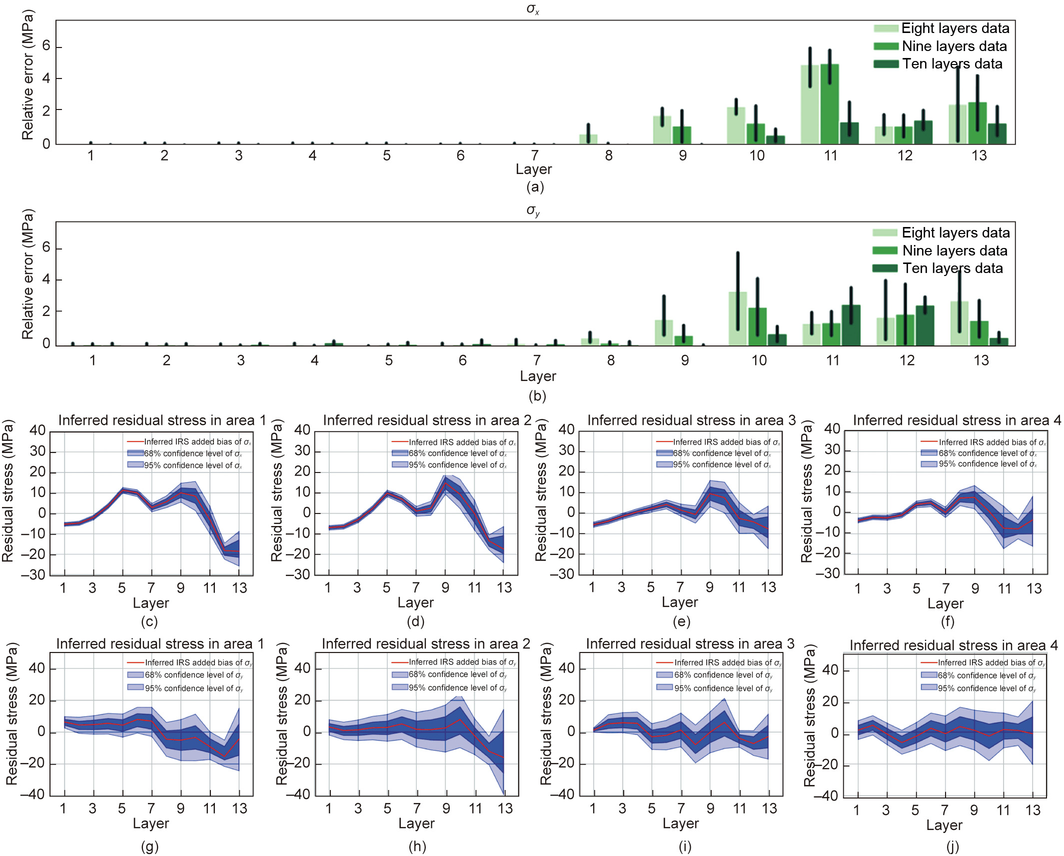
Fig. 9. Validation of the inferred results. (a, b) Inferred residual stress field difference between the data for the first eight, nine, and ten layers and the data for all 11 layers (baseline); (c–j) confidence level of the residual stress field in (c–f) the σx direction and (g–j) the σy direction. RSF: residual stress field.
To validate the accuracy of the inferred residual stress field, the subsequent deformation forces and final deformation were predicted as the validation indexes. The predicted deformation forces and deformation are shown in Figs. 10 and 11. It can be seen that the trends in the residual stress measured by the other two existing methods are similar to the trend in the residual stress field, but the measurement values are not accurate. Fig. 11(f) compares results from the proposed method with the other two existing methods, as shown in Figs. 10(e)–(h). The RMSE of the X-ray diffraction method is the largest. The RMSEs of the hole-drilling method are 25 times greater than those of the proposed method, which are 53.05 and 2.31 N, respectively. Moreover, the proposed method has a smaller maximum prediction error of 6.57 N, compared with 77.44 N for the hole-drilling method. This evidence indicates the stability of the proposed method for residual stress field inference. More prediction results and the inferred probability of the residual stress field are provided in Note C in Appendix A.
《Fig. 10》

Fig. 10. Validation of the deformation forces caused by residual stress field. (a–d) Fitted deformation forces by the destructive and X-ray diffraction methods; (e–h) comparison of the predicted deformation forces.
《Fig. 11》
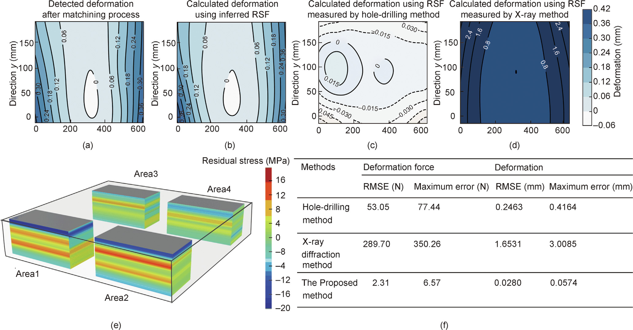
Fig. 11. Validation of deformation caused by the residual stress field. (a–d) Detected deformation after the machining process and calculated deformation using the residual stress field obtained by three methods; (e) inferred residual stress field; (f) comparison of the predicted deformation forces and deformation results by the three methods.
The deformation of parts caused by the residual stress field was also analyzed. The deformation of the part that was detected after machining was compared with the calculated deformation according to finite-element methods using the inferred residual stress field. The deformation contours are illustrated in Figs. 11(a)–(d), and the inferred residual stress field is shown in Fig. 11(e). It can be seen that the deformation trend calculated using the residual stress field inferred by the proposed method is consistent with the actual detected deformation. Moreover, in the comparative error analysis, as illustrated in Fig. 11(f), the RMSE of the proposed method is 0.0280 mm and the maximum error is 0.0574 mm, both of which are smaller than the errors of the other two existing methods. We also carried out experiments on more actual aircraft parts, which are provided in Note D in Appendix A. The experimental results all demonstrated that the deformation forces and deformation obtained from the residual stress field inferred by means of the proposed method were closer to the real situation. It can be concluded that the proposed residual stress inference method is more accurate and stable than the existing methods.
《4. Discussions, conclusions, and further work》
4. Discussions, conclusions, and further work
The factors affecting the inference accuracy of the residual stress field include the accuracy of the measurement of deformation forces and the zoning strategy of the residual stress field according to prior knowledge of the residual stress field distribution. The accuracy of deformation force measurement is affected by the residual stress caused by machining and gravity (especially for large parts). For the aluminum alloy used in the experiments, the residual stress caused by milling was small and could be ignored; however, for difficult-to-cut materials such as titanium alloys, the residual stress caused by machining operations could be considered in the matrix M. In the experiment, the influence of chips and cutting fluid on the deformation force measurement was reduced by means of instant cleaning during the material removal process. The factors affecting the resolution of the inferred residual stress field mainly include the size of the parts and the number of deformation force measurements required by different machining processes. A higher resolution can be obtained by measuring more deformation forces for a smaller part. In addition, the proposed method requires changing the geometry of the parts through certain machining operations so as to result in an unbalanced residual stress field and deformation forces. This requirement can be met by obtaining deformation force data during the normally planned manufacturing operations, without the need for carrying out additional separate measurements or experiments—unlike existing destructive or non-destructive methods.
In conclusion, this paper introduced a new residual stress field inference method using deformation force data obtained from sensors installed in fixturing and clamping equipment during a real machining process. The proposed method improves the accuracy, reliability, and resolution of residual stress field inference for large high-value parts using area partitioning and online deformation force monitoring data. It was validated using a part manufactured in our laboratory and parts from industry. We demonstrated its application for aircraft structural parts with accurate and reliable residual stress field results. This method also has potential application for residual stress measurement in additivemanufacturing. Accurate inference of the residual stress field of individual parts is important to the whole life-cycle management of the residual stress of parts and will greatly improve current practices in the quality control of part machining and the fatigue life analysis of large parts. The principles of the proposed method provide an important reference for measuring and analyzing residual stress during real manufacturing via dynamic monitoring data, which is essential in today’s digital and intelligent manufacturing systems.
In our ongoing and further work, we will explore the application of this method for different parts and materials in the aerospace, nuclear, and ship-building industries. Other research will explore how to reduce the ill condition of the volume coefficient matrix M by optimizing the layout of the monitoring system for deformation forces and the sequence of material removal so that the overall residual stress distribution field can be accurately inferred while requiring less deformation force data to be obtained during the material removal process.
《Acknowledgments》
Acknowledgments
The reported research was financial supported by the National Science Foundation of China for Distinguished Young Scholars (51925505) led by Yingguang Li, and funding was obtained from the National Natural Science Foundation of China (52175467 and 51775278) led by Changqing Liu.
《Compliance with ethics guidelines》
Compliance with ethics guidelines
Zhiwei Zhao, Changqing Liu, Yingguang Li, and James Gao declare that they have no conflict of interest or financial conflicts to disclose.
《Appendix A. Supplementary data》
Appendix A. Supplementary data
Supplementary data to this article can be found online at https://doi.org/10.1016/j.eng.2022.07.018.


 京公网安备 11010502051620号


