《1. Introduction》
1. Introduction
In vitro tissue models such as those based on cellular spheroids have attracted increasing interest in cellular biology, tissue engineering, regenerative medicine, and drug-screening applications [1−4]. Cellular spheroids are three-dimensional (3D) aggregates of multi-cells, which usually scale from tens to hundreds of micrometers. It is widely accepted that cells in cellular spheroids behave and respond to changes in microenvironment cues in a much more natural manner than those on traditional two-dimensional (2D) culture plates [5,6]. In addition, cellular spheroids are inherently scaffold free as compared to scaffold-based 3D models; this property may help cellular spheroids to avoid biocompatibility issues [7]. Different types of cells have been engineered into cellular spheroids, including normal [8,9], cancerous [10,11], and stem cells [12,13], as well as a mixture of cell types [14,15]. In particular, the introduction of chip technologies has recently inspired the emergence and prominent development of tissue/organ-on-a-chip technology, which is believed to hold great promise in biomedical fields [16−18].
Various methods have been developed for generating cellular spheroids by exploring the fluidic and self-assembly abilities of cells [19]. A facile method is to culture cells on non-adherent substrates [20], where the cell-cell interaction is stronger than that of cell-substrate, resulting in the aggregation of cells. To promote the assembly of cells, gravitational and magnetic forces have been explored, leading to the development of the hanging-drop [21] and magnetic-levitation methods [22], respectively. Microwells have also been widely used to confine the growth space of cells with the benefit of forming cellular spheroids with controlled and uniform size [11]. Among these methods, microwells have attracted increasing attention; especially those with concave structures, due to advantages such as easy operation, good controllability, and high-throughput capacity [23,24]. However, almost all of the current microwell methods require the manual seeding of cells after the preparation of a microwell plate, which may be cumbersome and can cause cell loss and non-uniform cell seeding [25]. In addition, special templates and a careful molding process are required to obtain well-defined concave microwells, which limits their accessibility. Therefore, there is still an urgent need for a flexible manufacturing method for fabricating cellular spheroids, particularly those with the potential for engineering tissues on chips.
In this study, we developed a bioprinting-based method for fabricating concave wells and generating cellular spheroids in situ on a chip. A custom-built bioprinting system was first constructed and applied in order to generate cell-laden sacrificial gelatin arrays. These cell-laden gelatin arrays were subsequently used as templates for fabricating concave wells and forming cellular spheroids on a non-adhesive hydrogel substrate. The method is facile and, to the best of our knowledge, represents the first use of biocompatible hydrogels as templates for fabricating concave wells with in situ cell-seeding ability for cellular spheroid formation.
《2. Materials and methods》
2. Materials and methods
《2.1. Set-up and improvement of the bioprinting system》
2.1. Set-up and improvement of the bioprinting system
To get high controllability for the droplet generation of gelatin sol, a pressure-assisted value-based bioprinting system was applied. This system was custom built, and is shown in Figure 1(a). The system was set up in a vertical laminar-flow clean workbench, with the main components being a three-axis motion stage (KDT180-100-LM ( XY) and MT105-50-LM ( Z), Feinmess Dresden GmbH, Dresden, Germany), a solenoid valve ejector (Model G100-150300, TechElan, Mountainside, NJ, USA), and a digital signal generator (Agilent 81101A, Test Equipment Connection, Lake Mary, FL, USA). All of these components were controlled using a computer.
《Fig. 1》
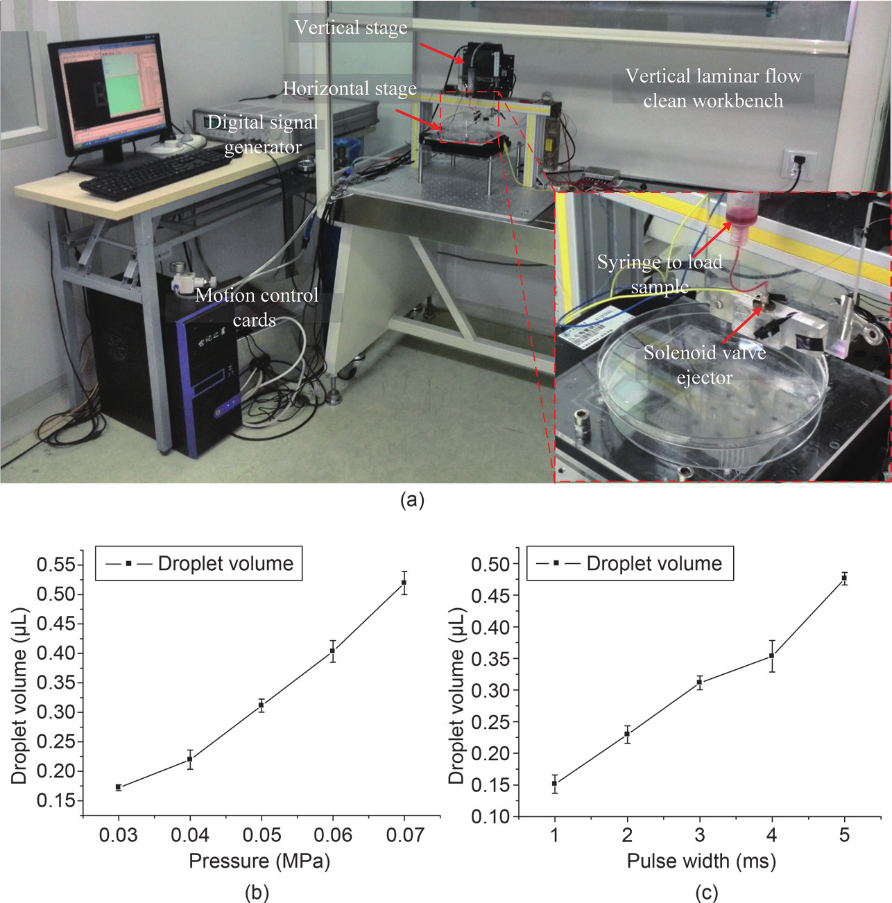
Fig.1 Bioprinting platform. (a) Image of the bioprinting platform; (b) mean droplet volume as a function of pneumatic pressure, and the valve-opening duration is 5 ms; (c) mean droplet volume as a function of valve-opening duration, and the pneumatic pressure is 0.05 MPa. Error bars represent standard error ( n = 5).
《2.2. Bioprinting-based fabrication of sacrificial gelatin arrays》
2.2. Bioprinting-based fabrication of sacrificial gelatin arrays
Gelatin was chosen for the sacrificial hydrogel arrays due to its biocompatibility and its injectable and reversible gelling abilities under mild temperature conditions. To fabricate the gelatin arrays, porcine-skin gelatin powder (gel strength 300, Type A, Sigma-Aldrich, St. Louis, MO, USA) was added to a phosphate-buffered saline (PBS) solution at a concentration of 3% (w/v) and gently stirred at 50°C until fully dissolved. The sol solution was then water-bathed to 37°C, transferred to the sample-holding syringe, and printed onto a culture petri dish coated with a polytetrafluoroethene (PTFE) membrane. The PTFE membrane was used because it is physically hydrophobic and chemically inert, as well as easy to use. The temperature of the gelatin solution in the syringe was kept at 37°C during printing. The assisted printing pressure and pulse width of the signal were adjusted to control the printed volume of the gelatin droplet and thus the size and shape of the gelatin arrays. The petri dish with the printed gelatin arrays was immediately transferred to a refrigerator and cooled at 4°C for 5 min in order to gel the gelatin precusor.
《2.3. Gelatin-array templated fabrication of concave wells》
2.3. Gelatin-array templated fabrication of concave wells
Polyethylene glycol (PEG)-based hydrogels were used to mold concave wells from gelatin arrays due to their biocompatibility, photocrosslinkability, and cell-nonadhesive properties. These hydrogels have also been used by others to fabricate wells for the formation of cellular spheroids [26−28]. In our experiment, PEG-dimethacrylate (PEG-DMA, MW 1000, Polysciences, Inc., Warrington, PA, USA) was dissolved in a PBS solution at a concentration of 20% (w/v) and then cooled to 4°C. After being poured onto the petri dish with the gelatin arrays, the PEG-DMA solution was exposed to 365 nm ultraviolet (UV) light with a power of 2.9 mW.cm−2 (Model XLE-1000 A/F, Spectroline, Westbury, NY, USA) for 20 s for gelling. During the photocrosslinking, 2-hydroxy-2-methylpropiophenone (TCI Shanghai Development Co., Ltd., Shanghai, China) was used as the photoinitiator at a concentration of 0.1% (w/v). After incubation at 37°C for 24 h, the gelatin arrays redissolved into a sol phase and concave wells formed on the PEG-DMA substrate.
《2.4. Characterization of gelatin arrays and concave wells》
2.4. Characterization of gelatin arrays and concave wells
The gelatin arrays were imaged with an inverted fluorescence microscope (Olympus IX 81, Olympus, Irvine, CA, USA) before molding with PEG-DMA. To image the wells, the PEG-DMA substrate was gently detached from the PTFE-covered petri dish, and swelled to equilibrium in a PBS solution. After being taken out of the PBS solution, the excess PBS solution on the PEG-DMA substrate surface and in the wells was gently removed with blotting paper. To capture a cross-section of the wells, the PEG-DMA substrate was carefully cut through the wells with a razor blade and images were immediately taken with an IX 81 microscope. The images were analyzed with Image-Pro Plus (IPP, version 6.0, Media Cybernetics, Silver Spring, Rockville, MD, USA) to quantify the sizes of the gelatin arrays and wells on the PEG-DMA substrate.
《2.5. In situ cell seeding and cellular spheroid formation》
2.5. In situ cell seeding and cellular spheroid formation
We used MCF-7 human breast cancer cells to verify the in situ cell-seeding ability of our method for the high-throughput fabrication of cellular spheroids on a chip. Cells were cultured in RPMI 1640 medium (HyClone, South Logan, UT, USA) and supplemented with 10% fetal bovine serum (Gibco Industries, Inc., Big Cabin, OK, USA) in a humidified 5% CO2 incubator at 37°C. Before the experiment, the cells were digested with trypsin (EDTA 1×, Mediatech, Inc., Manassas, VA, USA) and centrifuged, and the liquid supernatant was removed. The cells were then resuspended in the culture medium. The prepared cellular suspension was then gently mixed with a pre-filtered gelatin solution at a final cell density of 5 × 10⁵ cells.mL−1 to 1 × 10⁶ cells.mL−1 and a gelatin concentration of 3% (w/v) at 37°C. The cell-gelatin mixture was then loaded into the syringe for the fabrication of the gelatin arrays and wells as described in Sections 2.2 and 2.3. The petri dish cover was removed after incubation for 1 h and the cell culture medium was changed daily. Phase-contrast images of the cellular spheroids were observed with an Olympus IX 81. Confocal fluorescence images (LSM700, ZEISS, New York, NY, USA) were observed after the spheroids or aggregates were stained using a live/dead viability/cytotoxicity kit (Invitrogen, Washington, DC, USA). The kit stained live cells green with calcein AM and dead cells red with ethidium homodimer-1. Cell viability was quantified from confocal slices using IPP.
《3. Results and discussion》
3. Results and discussion
The bioprinting system we constructed is shown in Figure 1(a). High controllability of the bioprinting system for producing droplets of nL volume was demonstrated; this controllability can be achieved by changing the pneumatic pressure or the valve-opening duration, as shown in Figure 1(b) and Figure 1(c), respectively. The optimized concentration of the gelatin sol solution was found to be ~3% (w/v), below which the gelatin arrays were too soft to be used as templates and above which valve blocking and solution ponding occurred.
The bioprinting system was then applied to produce controlled gelatin arrays for fabricating concave wells and in situ cellular spheroid formation, as illustrated in Figure 2. First, gelatin arrays of different sizes were created on a hydrophobic PTFE-covered petri dish, as shown in Figure 3(a−c). After molding, concave wells were formed on the PEG-DMA substrate with almost the same size as the gelatin-array templates, as shown in Figure 3(d−f), demonstrating the high molding fidelity and thus the feasibility of using gelatin arrays as templates. By tuning the volume of the printed gelatin droplets from 0.1 μL to 0.48 μL, gelatin arrays with a radius ranging from 420 μm to 530 μm and a depth ranging from 230 μm to 550 μm can be easily obtained, as shown in Figure 3(g). This method led to the formation of concave wells with a radius ranging from 480 μm to 530 μm and a depth ranging from 250 μm to 550 μm, as shown in Figure 3(h). The droplet volume can be easily tuned by adjusting either the printing pressure or the pulse width of the digital signal. Since high pressure may lead to cell damage and an unwantedly forceful impact between the gelatin droplet and the substrate, we only tuned the pulse signal width to control the gelatin droplet volume. Wells with a high depth may have the advantage of avoiding cell loss during the medium exchange. We expect that wells with a much more controlled size and a higher molding fidelity could be fabricated by optimizing the production of the gelatin arrays, which may be achieved by improving the gelatin droplet hydrophobic angle by use of more hydrophobic substrates.
《Fig. 2》

Fig.2 Schematics of concave-well fabrication and in situ cell seeding for cellular spheroid formation. (a) Cover the petri dish with a film layer of hydrophobic PTFE; (b) print gelatin and cell solution onto PTFE-covered petri dish; (c) cell-encapsulated hydrogel array forms when cooled at 4°C; (d) pour the cold PEG-DMA solution onto the cell-encapsulated gelatin array and (e) expose it to UV light for crosslinking; (f) turn it over and incubate at 37°C to liquefy the gelatin and release cells onto the well bottom; (g) cellular spheroids form during further culture.
To prove the in situ cell-seeding ability of our method for cellular spheroid formation on a chip, we first mixed MCF-7 cells with a gelatin precursor at a density of 1 × 10⁶ cells.mL−1 and printed the mixture at a volume of 0.48 μL per droplet. After molding and incubation at 37°C for 1 h, the gelatin arrays reversed to the sol phase and the cells, encapsulated in gelatin, were released and deposited onto the bottom of wells formed on the PEG-DMA substrate. During the subsequent culture, the cells proliferated, huddled together, and finally self-assembled into compacted cellular spheroids on the 7th day, as shown in Figure 4(a). We observed very few dead cells throughout the process, as shown in Figure 4(b). Cellular spheroid formation with a printed volume of 0.23 μL and the same cell-seeding density (i.e., 1 × 10⁶ cells.mL−1) was also studied. Although cellular aggregates were observed after 7 days of culture, these were not as compacted as those in the 0.48 μL group, as shown in Figure 4(c). The observed cellular aggregates did not change notably even after 14 days of culture (results not shown here). The horizontal cross-sectional confocal fluorescence image in Figure 4(b) shows that there is a black central domain without stained cells, which may be induced by diffusion limitation of the live/dead solution in compacted cellular spheroids. This central domain is not observed in Figure 4(d), indicating that the formed cellular aggregates with a printed gelatin volume of 0.23 μL may be in a disk shape. From Figure 3(f) and Figure 3(h), we know that the fabricated wells with printed gelatin volumes of 0.23 μL and 0.48 μL per droplet have radiuses of 480 μm and 530 μm, and depths of 390 μm and 550 μm, respectively. Thus, it seems to us that well depth may play an important role in the formation of compacted cellular spheroids.
《Fig. 3》

Fig.3 Controlled fabrication of hydrogel concave wells. (a) Overall view of printed gelatin arrays of different sizes on a PTFE-covered petri dish; (b) top-view microscope image of the gelatin arrays; (c) side view of two typical gelled gelatin droplets; (d) overall view of concave wells formed on PEG-DMA; (e) top-view microscope image of PEG-DMA wells; (f) side view of the cross-section of the concave wells; (g) controllability of the sizes of gelatin arrays; (h) controllability of the sizes of concave wells. Scale bars in (b), (c), (e), and (f) are 0.5 mm. Error bars in (g) and (h) represent standard deviation ( n = 5).
We further investigated the influence of initial in situ cell-seeding density on the formation of cellular spheroids. The results clearly showed that much smaller cellular spheroids were formed at a cell-seeding density of 5 × 10⁵ cells.mL−1, as shown in Figure 4(e)−(h), compared to a density of 1 × 10⁶ cells.mL−1, as shown in Figure 4(a)−(d). Therefore, it is possible to control the size of cellular spheroids by adjusting the in situ cell-seeding density. Figure 4(i) shows that high cell viability was maintained during cellular spheroid formation. In addition, cell loss was effectively avoided with the in situ cell-seeding ability. Moreover, uniform distribution of seeded cells between wells was achieved due to the controllability of the bioprinting system. Morphologically speaking, cellular spheroids can better mimic the structure of organoids and thus the microenvironment of cancer cells in vivo than can traditional 2D culture plates. It is therefore expected that MCF-7 may behave similarly in cellular spheroids and in vivo. To demonstrate this, further studies including a drug test are needed; these will be our next work. Although we only tested MCF-7 cells here, we believe that other cell types can be used, since gelatin has been widely applied for cell encapsulation and since a polyethylene glycol (PEG) hydrogel-based well plate has been successfully used for producing cellular spheroids of various cell types, including embryonic stem cells [29,30].
《Fig. 4》
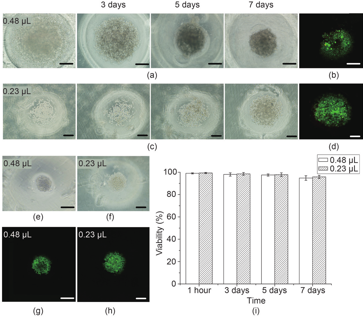
Fig.4 Cellular spheroid formation in hydrogel concave wells. (a) Phase-contrast images of cellular spheroid development and (b) calcein and ethidium bromide staining of cells after 7 days of culture in wells made of 0.48 μL gelatin droplets and with a cell-seeding density of 1 × 10⁶ cells·mL−1; (c) phase-contrast images of cellular spheroid development and (d) calcein and ethidium bromide staining of cells after 7 days of culture in wells made of 0.23 μL gelatin droplets and with a cell-seeding density of 1 × 10⁶ cells·mL−1; (e, f) phase-contrast images of cellular spheroid formation after 7 days of culture in wells made of (e) 0.48 μL and (f) 0.23 μL gelatin droplets, with a cell-seeding density of 5 × 10⁵ cells·mL−1; (g, h) live/dead fluorescence images corresponding to (e) and (f), respectively; (i) cell viability during cellular spheroid formation. Scale bars in (a)−(h) are 200 μm.
Several researchers have demonstrated the use of molded or printed gelatin sacrificial elements for fabricating microfluidic hydrogels. In this work, we employed gelatin arrays as templates for the first time to generate concave wells for cellular spheroid formation. Although other templates, including solid resin mold, SU-8, polydimethylsiloxane (PDMS), and ice array, have been developed for fabricating concave wells, these methods suffer from either cumbersome mold preparation or destructive demolding operations [23,31−33]. In addition, the post manual cell-seeding step may cause cell loss and non-uniform cell distribution. Here, by using a biocompatible and temperature-reversible cell-laden gelatin-array template, we provide a possible solution to overcome the above limitations. Moreover, the use of a custom-built bioprinting system may enable us to fabricate cellular spheroids in situ on a chip in a controlled and high-throughput manner, which will be of great help in engineering tissues on chips.
《4. Conclusions》
4. Conclusions
This work demonstrated the fabrication of concave wells molded from a hydrogel array with in situ seeding of cells for cellular spheroid formation on a chip. The use of a custom-built bioprinting approach endows the method with high controllability and a high-throughput capacity. The integration of bioprinting and in situ cell seeding with gelatin may enable highly programmed fabrication of cells/tissues on chips, and thus holds great promise for tissue engineering, regenerative medicine, and drug-screening applications.
《Acknowledgements》
Acknowledgements
This work was financially supported by the National Natural Science Foundation of China (11372243, 11532009, and 11522219), the China Postdoctoral Science Foundation (2013M540742), the Doctoral Program of Higher Education of China (20130201120071), the Natural Science Basic Research Plan in Shaanxi Province of China (2014JQ1004), and the Fundamental Research Funds for the Central Universities.
《Compliance with ethics guidelines》
Compliance with ethics guidelines
Kai Ling, Guoyou Huang, Juncong Liu, Xiaohui Zhang, Yufei Ma, Tianjian Lu, and Feng Xu declare that they have no conflict of interest or financial conflicts to disclose.


 京公网安备 11010502051620号


