
《1.Introduction》
1.Introduction
Membrane gas separation is a technology that is now widely accepted in industry. Examples of successful applications include the treatment of natural gas, oxygen/nitrogen (O2/N2) separation, hydrogen (H2) separation, reactant ratio adjustment, and the separation of volatile organic compounds from permanent gases. Among the benefits of membrane separation systems, their small footprint, ease of operation, and avoidance of potentially harmful solvents such as amine absorbents are of particular interest. Many years of successful operation of gas separation units in the aforementioned applications make this concept feasible for use in very sensitive areas where the stability of the membrane separation system is the key issue. This means that any membrane and membrane units aimed at practical application are tested scrupulously under the conditions of possible use, including some events of low probability. One such application is the separation of carbon dioxide (CO2) from the flue gases of fossil fuel-fired power plants, which represent one of the most challenging types of gas stream to be treated by membrane technology. In fact, the separation of greenhouse gases such as CO2 from dilute emissions was identified by Sholl and Lively [1] as one of the seven chemical separations that would change the world. The necessity of this type of separation is supported by numerous publications that report the increase of CO2 concentration in the atmosphere due to human activity, and the need for greenhouse gas emissions reduction [2]. In his recent article, Hawking [3] drew public attention to the issues of environmental preservation: “We face awesome environmental challenges: climate change, food production, overpopulation, the decimation of other species, epidemic disease, acidification of the oceans.”
The need to preserve the environment for future generations calls for the optimization of energy use in existing technological solutions and for the development of new processes employing regenerative feedstocks, which would relieve humanity from its dependence on fossil fuels. Unfortunately, fossil fuels will remain a major source of energy for transportation and industry for years or decades to come, due to their very attractive energy density and resource availability. This consideration justifies the investments of major funding bodies into research on CO2 removal from various industrial sources and into the search for methods of CO2 utilization— or, in a worst-case scenario, for underground CO2 storage. It must be noted, however, that current estimates for CO2 utilization predict that only a small fraction of the CO2 available from point sources can be employed in this way.
The process of CO2 removal from industrial off-gas sources is one of the least favorable separations for membrane technology. All of the sources originating from, for example, fossil fuel-fired power plants, the cement industry, or the steel industry are characterized by low pressure, low CO2 content, high humidity, and large amounts of aggressive gaseous and even solid impurities. For example, the off-gas of a hard coal-fired power plant, which is considered to be one of the most interesting application possibilities for membrane gas separation, contains about 13–15 vol% (on a dry basis) of CO2, traces of sulfur oxides (SOx) and nitrogen oxides (NOx), and dust (mostly gypsum crystals); it is also water vapor saturated. The amount of off-gas produced by a more-or-less standard power block of 600 MW is in the range of 1.5 × 10⁶ m3(STP)·h−1 [4]. In order to treat this enormous low-pressure gas stream, it is necessary to develop huge membrane units together with new types of vacuum pumps to provide the driving force for the separation process.
The technologies that are competing with membranes are developed or are under development, and include absorption and adsorption processes. One of the most attractive of these processes is carbonate looping, in which carbonates are formed during the contact of off-gas with metal oxides. Chemical absorption processes that utilize newly developed amine-based absorption liquids are also attractive for the separation of CO2 from flue gases[5].
This publication provides a summary of the development and testing of a carbon dioxide/nitrogen (CO2/N2) selective membrane based on a poly(ethylene oxide)-poly(butylene terephthalate) (PEOPBT) block copolymer, which has been trademarked under the name PolyActive™.
《2.Polymers》
2.Polymers
The separation process under consideration defines the materials that are suitable for the selective layer and the protection and support layers of the membrane. The separation of CO2 from flue gas is to be carried out at low feed/permeate pressure ratios (approx. 1 bar (1 bar = 105 Pa) feed and, in the best case, 10 mbar but most probably 50–200 mbar permeate pressures) [6], moderate temperatures (different concepts are considered [7], but the temperature range will most likely be 30–50 °C), high humidity, and substantial solid particle content. Pre-filtering on the feed side of the gas separation unit is essential, but the other separation conditions define clear requirements for the choice of selective material.
Since the kinetic diameters of CO2 and N2 are similar (3.3 Å and 3.64 Å, respectively), diffusion selectivity is considered insufficient to be used as the driver for the solution-diffusion mechanism separation; thus, it is necessary to look for materials with high affinity toward CO2 and to establish the separation mostly based on solubility selectivity. Rubbery polymers and polymers with functional groups that are able to provide a facilitated transport mechanism are the primary candidates for the separation under consideration. At the same time, some newly developed glassy polymers, which act primarily as diffusion selectivity-controlled media, offer extremely high permeability coefficients with relatively moderate CO2/N2 selectivity. These materials can be considered suitable for the first stage of a multi-stage separation, in which CO2 will be concentrated from 10–14 vol% in the flue gas to approximately 50 vol% in the permeate. Taking into account the low pressure ratio available for the first separation stage, a CO2/N2 selectivity of approximately 20 can be sufficient. Hence, by utilizing the high permeability of polymers that have similar gas transport properties to PIM-1, it will be possible to drastically reduce the required membrane area. Unfortunately, high free-volume glassy polymers are well known for fast and strong ageing, which thus far forbids the widespread use of these materials in practical membrane gas separation applications [8–10].
Membranes utilizing a facilitated transport mechanism for the separation of CO2 from various gas streams have been widely studied, but have not yet found practical application. The advantage of facilitated transport membranes is their high CO2/N2 selectivity, in some cases exceeding 140, which could allow single-stage enrichment of the CO2 from a diluted source to the 95 vol% that is required for liquefying CO2. However, extremely high feed/permeate pressure ratios are required for the realization of this high selectivity in practical applications. Drawbacks for this type of polymer include the poisoning of functional groups with impurities from the gas stream and a necessarily high humidity level for the “initiation” of effective and selective CO2 transport. Nevertheless, membranes working according to the facilitated transport mechanism have been successfully studied on a pilot plant scale [11,12] and showed interesting properties.
Polymers that are in a rubbery state under separation conditions and that do not have a significant specific interaction with CO2 , but rather a high affinity toward it, include poly(ethylene oxide) (PEO) and block copolymers containing PEO; these materials are of special interest as membrane materials[13].
Polymers consisting solely of ethylene oxide and block copolymers with a high content of PEO have been intensively studied since the 1980s for gas separation properties. The works of Kuehne and Friedlander [14] and Kawakami et al. [15] were among the first attempts to utilize a high solubility selectivity of CO2 over other gases in gas separation membranes. In the early 1990s, the membrane separation of CO2 from various gas streams began to be associated with climate issues. In these studies, PEO played an important role as a material in supported liquid membranes [16,17]. The use of PEO as a selective part of a block copolymer was studied by Okamoto et al. [18]. These studies showed the major potential of block copolymers for the separation of CO2 -containing gas mixtures, where the selectivity of the membrane material is mainly controlled by the solubility selectivity.
Very important advances in understanding the mechanism of transport through PEO-containing block copolymers were made by Bondar et al. [19] on an example of a poly(ether-b-amide) segmented copolymer, and by Metz et al. [20] on copolymers with very narrow molecular weight distributions of PEO blocks in a PEO-PBT block copolymer. Further thorough investigation of selective CO2 transport in polymers, along with certain guidelines on polymer structure selection, can be found in Lin and Freeman [21], among other sources. The permeabilities of all block copolymers were considered to be insufficient for an efficient gas separation process. Many attempts have been aimed at the improvement of PEO-containing polymers by physical blending with low molecular weight PEOs, or by forming an interpenetrating PEO-based network within the matrix polymer [22–24].
Among the successful attempts to develop polymeric gas separation membranes with PEO-containing selective layers, at least two membranes should be mentioned, both of which reached pilot plant testing. These are the Polaris™ membrane, which was developed by Membrane Technology and Research, Inc. [25,26], and the PolyActive™ multilayer composite membrane, which was developed at HZG (short for Helmholtz-Zentrum Geesthacht, formerly GKSS Research Center Geesthacht GmbH) [27,28]. Both membranes are thin-film composite flat sheets that demonstrate high CO2 permeances, accompanied by selectivities that are very close to the intrinsic selectivity of the selective layer material.
The group of polymers that is distributed under the tradename PolyActive™ has been studied extensively for post-combustion membrane separation applications [29–31]. PolyActive™ polymers are block copolymers consisting of a rigid block that provides mechanical stability to the polymer and a rubbery block that is responsible for the selective transport of gases. The rigid block material, poly(butylene terephthalate) (PBT), is soluble in a variety of organic solvents, thus making it possible to choose the solvent for the preparation of the membrane. The rubbery block material, PEO, provides a reasonable CO2 permeability coefficient and CO2/N2 selectivity in its rubbery, non-crystalline state. The length of the PEO block can be varied; thus, the permeability coefficient can be varied according to the content of the PEO block in the block copolymer [32]. The solubility of PolyActive™ polymers in various solvents gives a clear advantage to this type of polymer compared with other options such as Pebax® MH 1657, which is soluble in just a few solvents and solvent mixtures that are suitable for membrane fabrication.
Fig. 1 [33] presents the gas transport properties of PolyActive™ polymer types and of some other polymers. The single-gas permeation behavior of polymer films of a thickness of approximately 100 µm was investigated. It is clear that the CO2 permeability of the presented polymers increases with temperature, while the CO2/N2 selectivity decreases significantly. All PolyActive™ polymers have a CO2/N2 selectivity that is similar to that of Pebax® MH 1657, but they exceed this polymer in terms of CO2 permeability. Of the Pebax polymer family, only Pebax® 2533 can compete with PolyActive™ polymers regarding the CO2 permeability; however, the former shows significantly lower selectivity than the latter. PolyActive™ polymers with PEO block molecular weights of 3000 g·mol−1 (PolyActive™ 3000) and 4000 g·mol−1 (PolyActive™ 4000) show a transition when heated, starting at 30 °C; that is, the PEO blocks change from a crystalline to an amorphous state. These polymers are very interesting in terms of their CO2 permeability, which is superior to that of PolyActive™ polymers with a PEO block of 1500 g·mol−1 molecular weight (PolyActive™ 1500). However, PolyActive™ 3000 and PolyActive™ 4000 types can only be used for gas separation at temperatures significantly higher than room temperature, which imposes certain limitations on their use as membrane material. A thorough investigation is currently underway regarding the behavior of polymers with high molecular weight PEO blocks serving as a selective layer of a thin-film composite membrane (TFCM).
《Fig. 1》
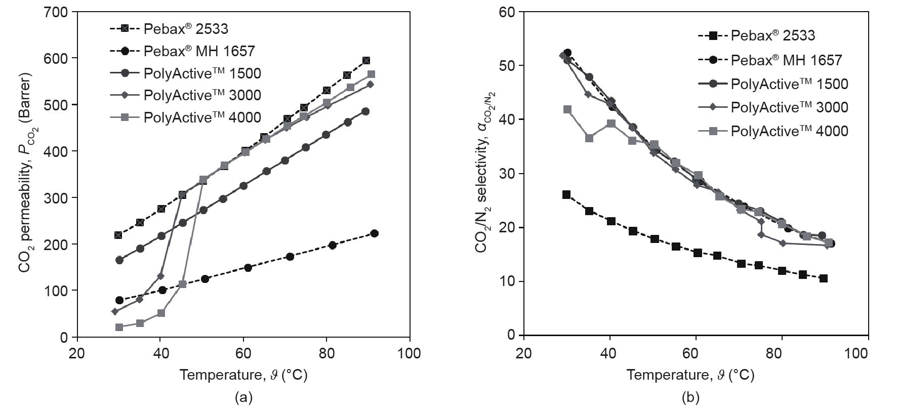
Fig. 1. (a) CO2 permeabilities (1 Barrer = 10-10 cm3 (STP)·cm·(cm2 ·s·cmHg)-1= 7.5006 × 10⁻¹⁸ m3 ·m·(m2 ·s·Pa) -1 ); (b) CO2/N2 selectivities of some PEO-containing block copolymers [33]. PolyActive™ 1500, 3000, and 4000 represent PolyActive™ polymers with PEO block molecular weights of 1500 g·mol−1, 3000 g·mol−1, and 4000 g·mol−1, respectively.
Fig. 2 [33] demonstrates significant differences in the PEOcontaining block copolymers’ behavior when they are employed as the material for the selective layer of a TFCM. The production of such membranes on a 100 m2 scale will be described in Section 3.1. The increase of the CO2 permeance above the PEO melting point is distinctively different for PolyActive™ 1500 and PolyActive™ 3000. The permeance of the Pebax® MH 1657-based TFCM is considerably lower than that of PolyActive™ polymers, whereas its selectivity exceeds that of PolyActive™ polymers at increasing temperatures. This behavior is in contrast to that observed for these polymers when they are studied as homogenous films with a thickness of approximately 100 µm; in the latter case, the selectivities of PolyActive™ polymers are similar to that of Pebax® MH 1657. At temperatures lower than the crystallization temperature, the TFCM with PolyActive™ 3000 as the selective layer shows a significant reduction in CO2/N2 selectivity, which is due to the formation of a dense crystalline phase in the PEO domains. This in turns leads to a loosened packing of PEO chains between crystallites.
《Fig. 2》
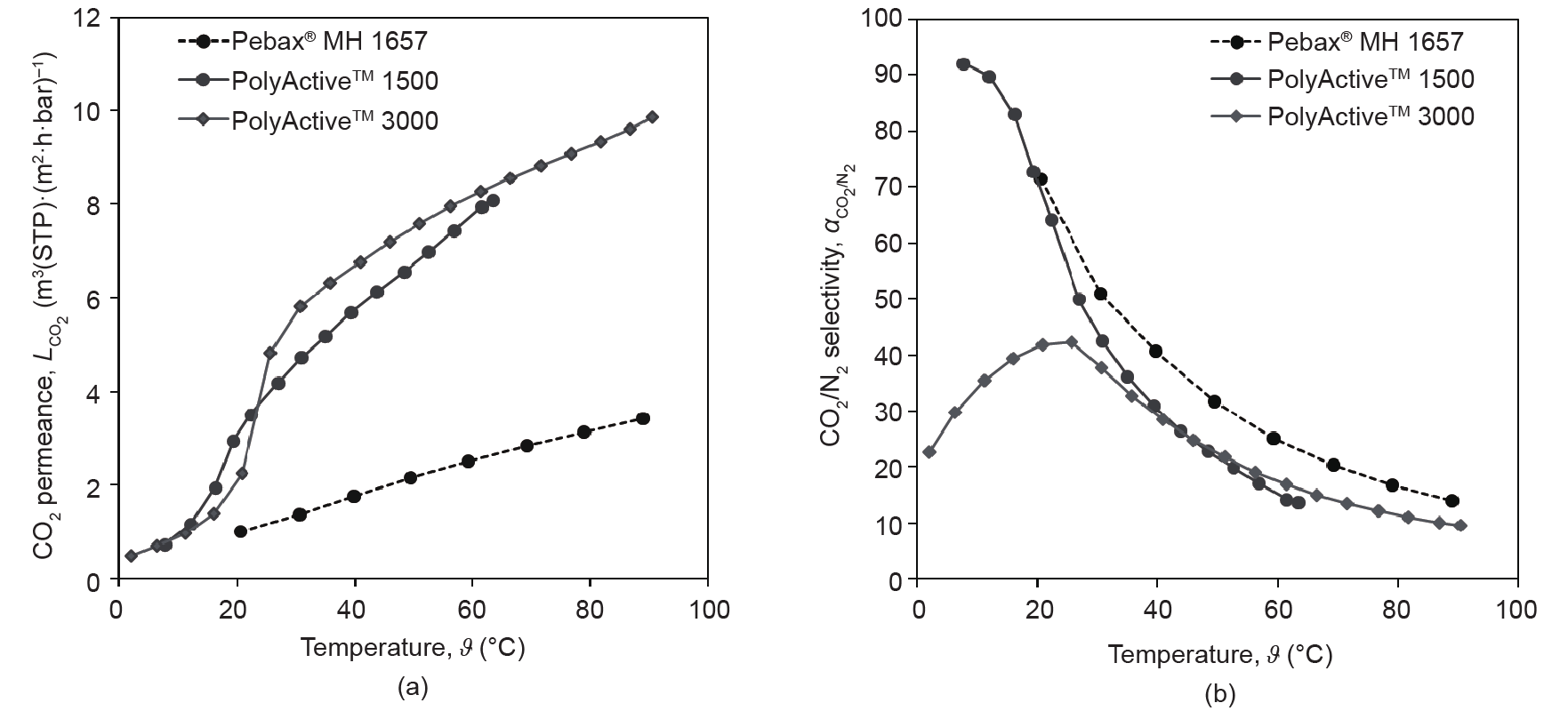
Fig. 2. (a) CO2 permeances and (b) CO2 /N2 selectivities of some experimental TFCMs with PEO-containing block copolymers as a selective layer. Membranes were prepared on a gutter layer membrane and were not coated with a protective layer [33].
Fig. 1 and Fig. 2 provide justification for employing PolyActive™ 1500 (referred to as PolyActive™ from this point on) as the selective layer material for TFCMs. Membranes based on this polymer can be used in a wide range of temperatures, and can be cooled down to ambient temperature during the shutdown periods of fossil fuelfired power plants, which are occurring more and more often due to large, non-continuous amounts of electric energy being fed into the grid from renewable sources.
《3.Transfer of membrane development to the technical scale》
3.Transfer of membrane development to the technical scale
《3.1. Membrane production》
3.1. Membrane production
Since 2008, numerous batches of PolyActive™ multilayer composite membrane have been produced as flat-sheet membranes, using the HZG pilot-scale membrane production infrastructure. This infrastructure consists of a membrane-casting machine for preparing the porous poly(acrylonitrile) support on polyester non-woven by phase inversion. The support is described by Scharnagl and Buschatz [34]. It has a thickness of approximately 40 µm, a mean pore size of 20 nm, and a surface porosity of 15%. After washing the support structure, the dense gutter, separation, and protection layers are applied by means of roller coating. These layers have typical thicknesses of 130 nm, 85 nm, and 150 nm, respectively. The membrane materials of the gutter and protection layers are poly(dimethylsiloxane)-based, whereas the material of the separation layer is PolyActive™. Fig. 3 [28] shows the structure of the support, gutter, and separation layers. The machines used are presented in Ref. [35], and details on the produced membranes can be found in Refs. [28,36,37]. Typically, rolls of 250 m in length and of either 0.3 m or 0.7 m in breadth are produced. The quality of such a batch was monitored with respect to selectivity and permeance, and was found to be satisfactorily uniform within the batch. The CO2 permeance of the membrane was increased from 2.7 m3(STP)·(m2·h·bar)−1 at 20 °C in 2008 to 4.0 m3(STP)·(m2·h·bar)−1 at 20 °C in 2016, with a CO2/N2 selectivity that exceeded 55 at this temperature in both cases. Fig. 4 shows the CO2/N2 selectivities and CO2 permeances measured along such a membrane. Since the produced membrane material was of high quality, it was employed to equip several membrane modules of different types.
《Fig. 3》
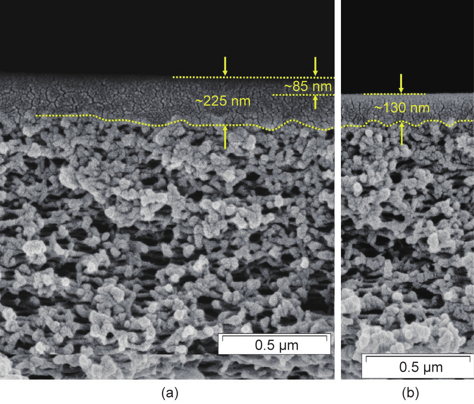
Fig. 3. TFCM structure: (a) porous support (poly(acrylonitrile)), gutter (poly(dimethylsiloxane)), and selective layer (PolyActive™); (b) porous support and gutter layer [28].
《Fig. 4》
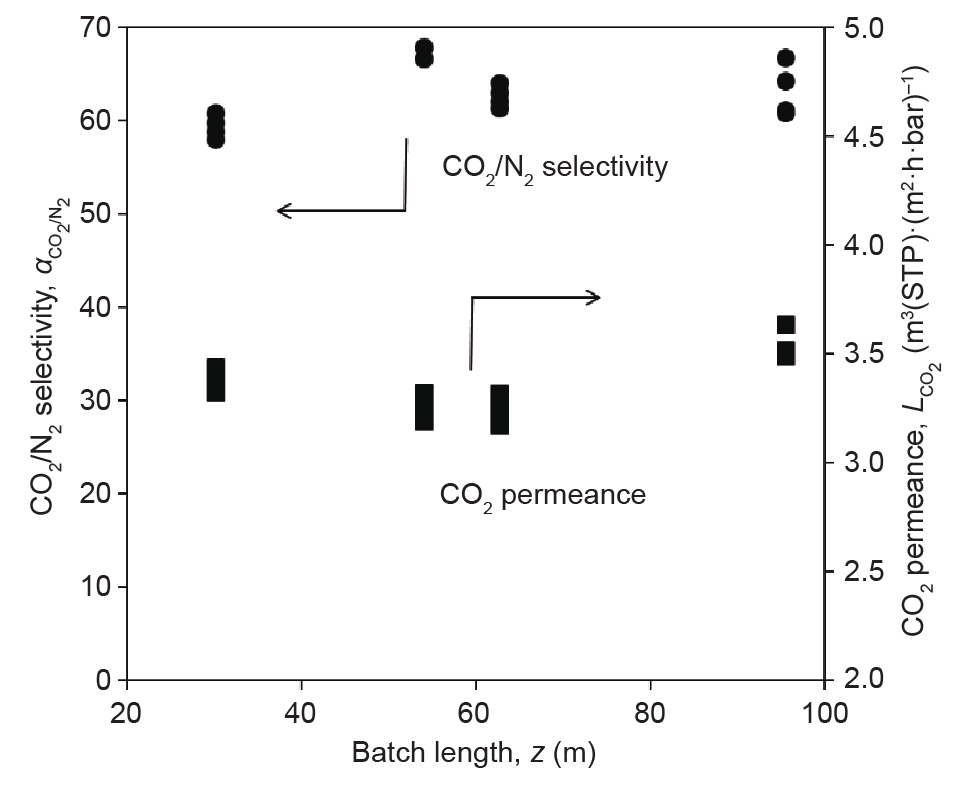
Fig. 4. CO2/N2 selectivities and CO2 permeances measured during quality control in the manufacture of a membrane batch. All values were determined from single-gas measurements at 3 bar or 6 bar feed pressure for CO2 and 11 bar feed pressure for N2 at 21 °C with a sample size of 34.2 cm2. The data is taken from current membrane production batches.
《3.2. Membrane modules》
3.2. Membrane modules
The classical membrane module for flat-sheet membranes is the spiral-wound module. The usage of this module type is widespread, not only in liquid-phase processing but also in membrane gas separation. The most significant use of this module type is for the separation of CO2 from natural gas [38,39]. Other modules, such as the envelope-type membrane module, are also suited for flat-sheet membranes. The envelope-type membrane module was developed by HZG and has been successfully employed in applications such as organic vapor recovery [40]. Its advantageous features include short permeate pathways and adjustable feed flow velocities, and it has a rather complex design when compared with spiral-wound modules. Hence, it is well suited for the application of modern high-flux membranes, especially in piloting scenarios, since negative effects such as concentration polarization and permeate side-pressure drops can be controlled. The maximum membrane area that can be installed is 75 m2 of the 310 mm type, where the packing density is up to 950 m2·m−3. Details on this membrane module can be found in Ref. [41], along with comparisons with the spiral-wound module and with a novel module type based on the envelope concept. The latter new type of module [42] was devised to allow the processing of extremely large flow rates at low pressures, which are typical for post-combustion applications in coal-fired power plants. At present, investigations with small-scale prototypes are underway in order to experimentally prove the viability of this module, after promising simulation results. It is envisaged that these envelopes will be housed in a 20 ft (1 ft = 0.3048 m) long container that will serve as the module and that will contain up to 15 000 m2 of membrane area. Fig. 5 [42] gives an impression of the design.
《Fig. 5》
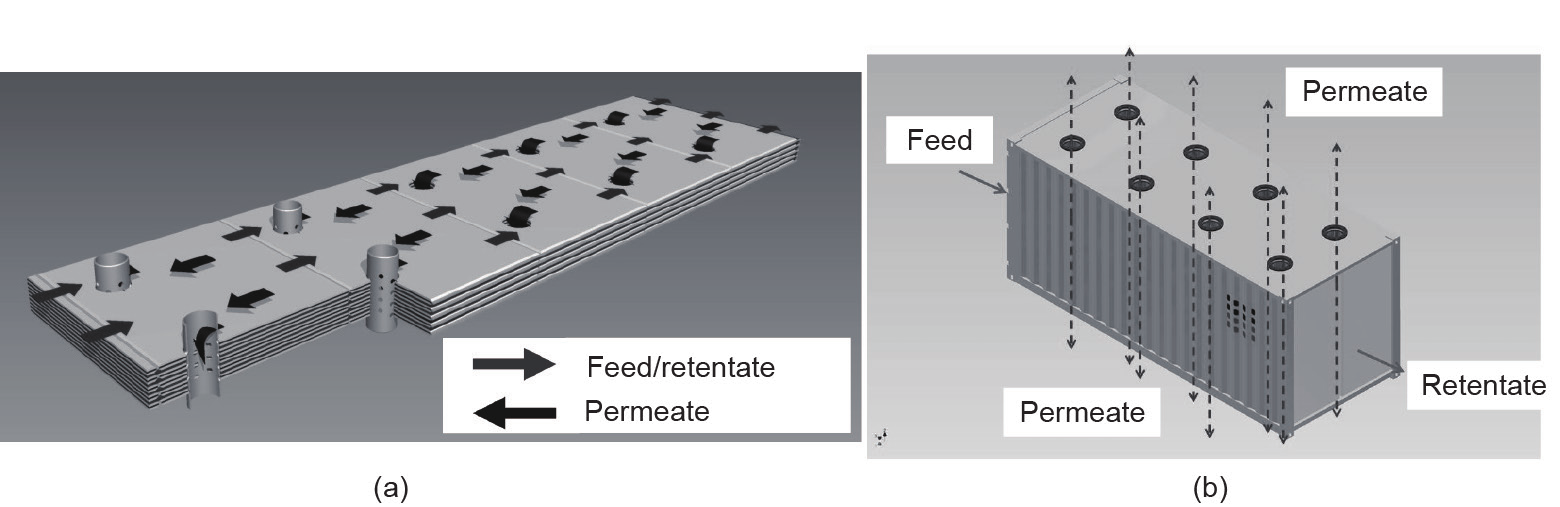
Fig. 5. The envelope-type membrane module concept for high-capacity, low-pressure applications. (a) Flow patterns on the feed/retentate and permeate sides of segmented rectangular membrane envelopes as well as permeate withdrawal via perforated pipes; (b) envisioned membrane module housing consisting of a 20 ft long container[42].
《3.3. Modeling membrane modules》
3.3. Modeling membrane modules
As implied in the previous section, mathematical models are of major importance when devising new types of membrane module, since they are able to depict the flow patterns present in the module. These flow patterns are expressed using the differential balances for material, energy, and momentum[43].These balances are simplified, for example, to consider only one spatial direction at steady-state conditions, and are coupled with the appropriate boundary conditions, such as feed conditions in terms of flow rate, temperature, pressure, and composition in flow direction, as well as the transmembrane mass and energy transfer perpendicular to the main flow direction. The transmembrane mass transfer encompasses the actual selective permeation process through the membrane and the detrimental mass transfer resistances in the boundary layers or in the porous support structures of the membranes. In order to properly account for the transmembrane mass and energy transfer, the permeate pressure at the permeate outlet of the module must be defined. Pressure drops are commonly accounted for by friction factor approaches. The solution of the resulting system of differential (or partial differential, if more than one spatial dimension and/ or dynamic scenario is considered) and algebraic equations requires numerical tools, such as those that are implemented in equationoriented process simulators. Examples of this process for flat-sheet membrane gas separation are shown in Refs. [41,44]. Brinkmann et al. [41] showed that when used for envelope-type membrane modules, this model very accurately predicts the experimental data col-
lected in a gas separation pilot plant for the separation of CO2 from N2 in the presence of water vapor for a 9.5 m2 membrane module. Fig. 6 [41] shows this model being used to determine the simulated CO2 retentate side mole fraction along the membrane surface for different flow rate and pressure conditions, and compares it with a value that was experimentally determined using gas chromatography.
Other important uses of the simulation models include the evaluation of experimental results, for example, since a comparison of the predictions of a validated model permits the detection of membrane failure. In addition, they are extremely useful for designing new processes, de-bottlenecking or expanding existing processes, making economic estimates, conducting life-cycle analyses, controlling the process, comparing process alternatives, and investigating possible operating failures.
《Fig. 6》
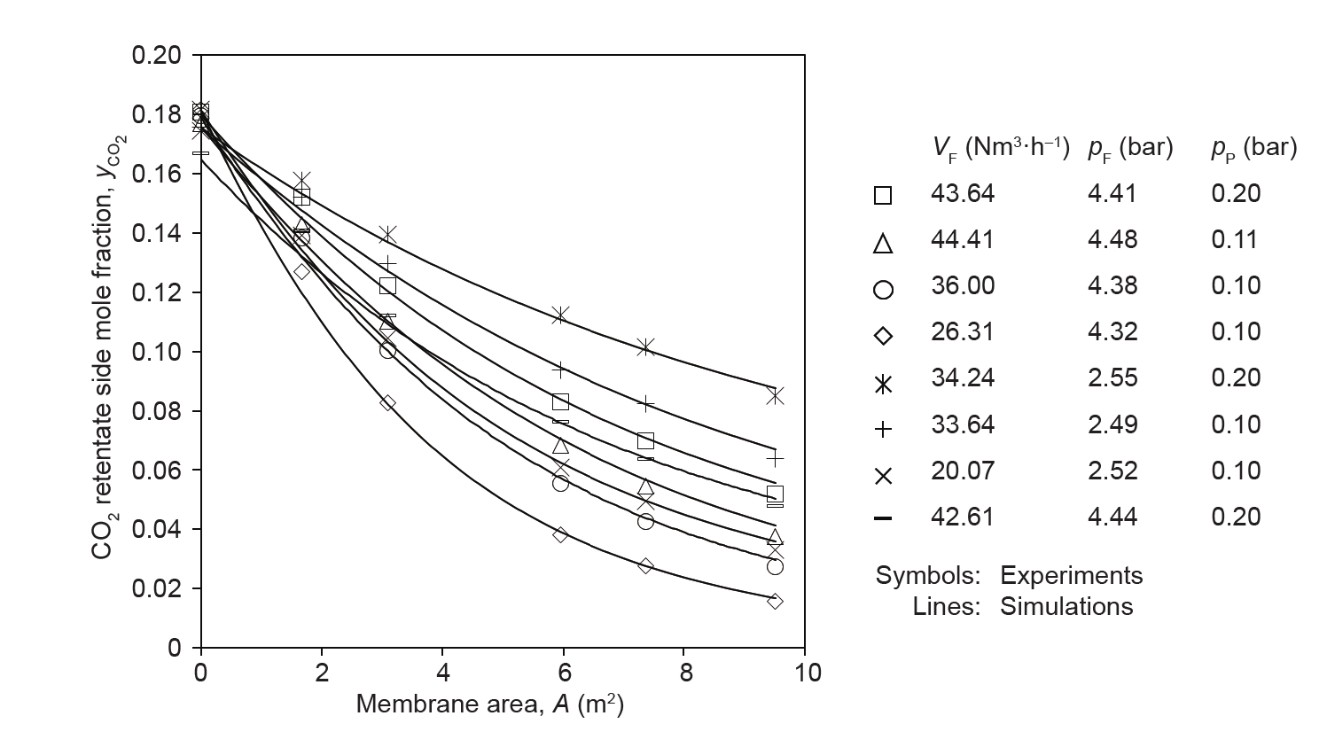
Fig. 6. Measured and simulated CO2 retentate side mole fractions along the surface of a PolyActive™ multilayer composite membrane installed in an envelope-type membrane module, investigated in a pilot plant with synthetic CO2/N2 mixtures that were water vapor saturated [41]. VF: volumetric feed flow rate; pF: feed pressure; pP: permeate pressure.
《3.4. Separation performance》
3.4. Separation performance
The development of the PolyActive™ multilayer composite membrane is clearly aimed at post-combustion processes in fossil fuel-fired power plants, heating systems, small-scale combined heat and power plants, and steel and cement plants. CO2/N2 separation is representative for these applications. However, in addition to its excellent selectivity for this separation, the PolyActive™ multilayer composite membrane was found to show a preferential permeation of CO2 compared with methane (CH4), C2 hydrocarbons, and H2. The latter is particularly interesting because H2 remains on the high-pressure side of the membrane. Table 1 [36] shows the selectivity values that were determined from single-gas experiments for a typical PolyActive™ multilayer composite membrane. The values are presented for a temperature of 30 °C in order to permit the inclusion of water vapor. Furthermore, the high water vapor permeance allows simultaneous CO2 separation from and water vapor dew-pointing of the retentate.
fuel-fired power plants, heating systems, small-scale combined heat and power plants, and steel and cement plants. CO2 /N2 separation is representative for these applications. However, in addition to its excellent selectivity for this separation, the PolyActive™ multilayer composite membrane was found to show a preferential permeation of CO2 compared with methane (CH4 ), C2 hydrocarbons, and H2 . The latter is particularly interesting because H2 remains on the
high-pressure side of the membrane. Table 1 [36] shows the selectivity values that were determined from single-gas experiments for a typical PolyActive™ multilayer composite membrane. The values are presented for a temperature of 30 °C in order to permit the inclusion of water vapor. Furthermore, the high water vapor permeance allows simultaneous CO2 separation from and water vapor dew-pointing of the retentate.
《Table 1》
Table 1 Selectivities of CO2 compared with other gases i  for PolyActive™ multilayer composite membranes at 30 °C [36].
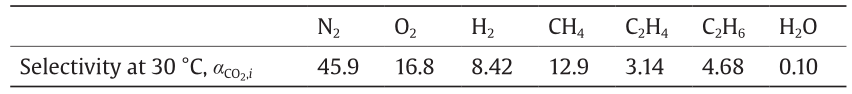
The selectivities were calculated from single-gas experiments. The CO2 permeance was 4 m3 (STP)·(m2 ·h·bar)−1 .
The temperature dependencies of the single-gas permeances can be expressed well using an Arrhenius-type relationship [36]. During these measurements, hardly any dependence on pressure was detected in the ranges investigated, that is, up to a pressure of 1.3 bar. Hence, swelling and components influencing each other in mixed gas permeation were neglected. Fig. 6 [41] shows that this assumption was justified, since single-gas permeation data was used to calculate the permeation behavior of the membrane, and the simulation gave an excellent representation of the experimental results. The permeation behavior at higher pressures, that is, those exceeding 10 bar, could no longer be predicted using single-gas permeation data on its own [36]. High-pressure permeation behavior is the subject of current research work.
《4.Process examples》
4.Process examples
《4.1. Small-scale utilization of CO2 contained in heating system flue gas》
4.1. Small-scale utilization of CO2 contained in heating system flue gas
As part of the international building exhibition in Hamburg in 2014, an apartment house equipped with algae bioreactors as facade elements was built. The CO2 required for the algae photosynthesis is provided by the flue gas of the natural gas-fired heating system of the building. For safety reasons, it is necessary for the algae solution to come into contact with the flue gas in order to dissolve the CO2. However, since the flue gas contains only 9 vol% CO2, the necessary CO2 concentration in the liquid phase for algae growth cannot be achieved by direct contact with the flue gas. A PolyActive™ membrane unit is therefore employed to increase the CO2 content to above 45 vol% in the permeate, which is sufficient to supply the required amount of CO2 to the algae [45]. The feed flow rate to this unit is 10–15 m3(STP)·h−1. It is supplied via a blower at ambient pressure and temperature to an envelope-type membrane module containing 11 m2 membrane area. A permeate pressure of 180 mbar is applied by a vacuum pump. The permeate is further compressed to 3.5 bar and is fed to a buffer vessel, from whence it is supplied to the saturator, operating at a pressure of 2 bar. The unit is operated intermittently; it starts when the pressure in the buffer vessel drops to 2 bar and stops when the pressure increases to 3.5 bar. This results in four or five 1 h operating periods per day. The retentate gas stream, which still contains 4–5 vol% CO2, is discharged. The unit was run in the described operating mode for more than one year, at which point the algae bioreactors were put into a planned revision period. Afterwards, the unit was restarted. Within the one-year period, the employed PolyActive™ multilayer composite membranes did not show any performance decline, as was proven by a comparison of the experimental results with those of the process simulation of the membrane unit. When describing the separation behavior of the module, the permeation performance of the PolyActive™ multilayer composite membrane was solely described using the single-gas permeation data of the production batch that was measured prior to installation into the module. Fig. 7 [45] shows the pilot plant and the comparison between the measured and simulated CO2 mole fractions.
《Fig. 7》

Fig. 7. Separation of CO2 from heating system flue gas for utilization in algae bioreactors. (a) The pilot plant; (b) the comparison between the measured and simulated CO2 mole fractions [45].
《4.2. Separation of CO2 from the flue gas of coal-fired power plants》
4.2. Separation of CO2 from the flue gas of coal-fired power plants
One typical post-combustion application of a PolyActive™ multilayer composite membrane unit is the separation of CO2 from the flue gas of coal-fired power plants. The separation of CO2 from the flue gas of a hard coal-fired power plant was an important topic investigated in the project METPORE II, which was funded by the German Federal Ministry for Economic Affairs and Energy[37]. The pilot plant was installed in a 20 ft long container and was equipped with a membrane stage for an envelope-type membrane module containing 12.5 m2 of PolyActive™ multilayer composite membrane. The feed was taken directly from the flue gas of the EnBW Rheinhafen-Steam power plant in Karlsruhe, Germany. It was supplied to the pilot plant by means of a blower at flow rates of 50–80 m3(STP)·h−1. The temperature and humidity levels were adjusted by a cooler/condenser followed by a superheater, such that feed temperatures between 25 °C and 50 °C were investigated at 5–10 K above dew point. The driving force was generated by applying a permeate side vacuum of 50–200 mbar by means of a liquid ring vacuum pump. Under the selected reference conditions (i.e., 70 m3(STP)·h−1 feed flow rate, 35 °C feed temperature, 25 °C feed dew point, 13 vol% CO2 in the feed, and 50 mbar permeate pressure) in the one-stage process that was investigated, a CO2 composition of 68.2 vol% was measured reproducibly in the recompressed permeate at the exhaust of the vacuum pump, with a CO2 recovery of 42.7%. Another important result of this study was the development of an operating strategy allowing for frequent startups and shutdowns of the membrane unit under the conditions imposed by the German energy-supply scenario. This energy supply is characterized by the integration of ever-increasing amounts of renewable energy at irregular intervals and loads. The study also included a thorough investigation of the removal of acidic condensates and of the removal of the humidity contained in flue gases in general. Fig. 8 shows the pilot plant and the CO2 composition profiles for the feed and permeate that were recorded over a total operating period of 750 h. The figure also provides a comparison between simulated and measured CO2 compositions in the permeate, again exemplifying the accuracy of the simulation model. The frequent startups and shutdowns are apparent in the graph.
《Fig. 8》
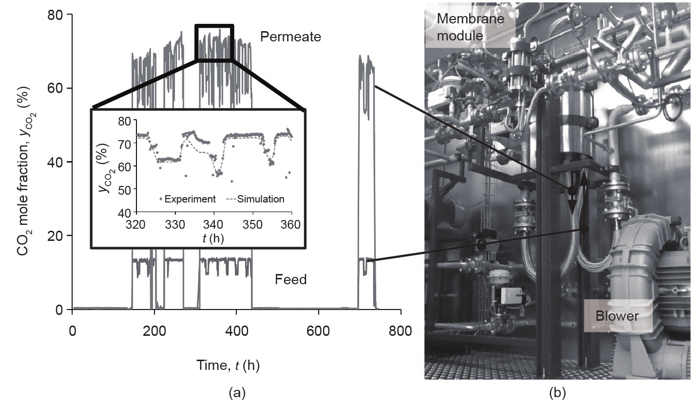
Fig. 8. Separation of CO2 from coal-fired power plant flue gas. (a) The CO2 composition profiles for the feed and permeate; (b) the pilot plant.
《4.3. Separation of CO2 from biogas》
4.3. Separation of CO2 from biogas
Another possible application is the separation of CO2 from biogas [36]. For this separation, which is represented by the binary CO2/ CH4 separation, the selectivity of PolyActive™ multilayer composite membrane is low, as shown in Table 1, when compared with those of other materials such as polyimides [46]. However, the permeance of PolyActive™ multilayer composite membranes is an order of magnitude higher than that of the flat-sheet membranes made of glassy polymers that are typically employed for this separation, such as Matrimid® [47]. Very compact one-stage units can be devised that achieve a CH4 mole fraction that meets pipeline specifications in the retentate with simultaneous water vapor dew-pointing. However, the permeate would still contain roughly 35–40 vol% CH4, which would render the whole process thoroughly uneconomical. If a consumer such as a boiler or gas engine is available onsite, however, the situation may change, since the permeate gas can be usable for energy generation. Fig. 9 [36] shows such a scenario, employing a gas engine. The power generated can be used to drive compressors, or can be fed into the electrical grid. The co-produced heat can be used for onsite heating purposes, such as to keep the fermenters at the required temperature. A pilot plant investigation at an operating biogas plant showed that such a membrane separation stage is feasible and can be operated with reproducible results over a period of several months [36]. The envelope-type membrane module was equipped with 7.4 m2 of PolyActive™ multilayer composite membrane. A typical operating point was a biogas feed flow rate of 45 m3 (STP)·h-1 containing 64 vol% CH4 compressed to 9 bar at 20 °C. The retentate contained 95 vol% CH4, whereas the permeate contained 35 vol% with a stage cut of 51%.
《Fig. 9》
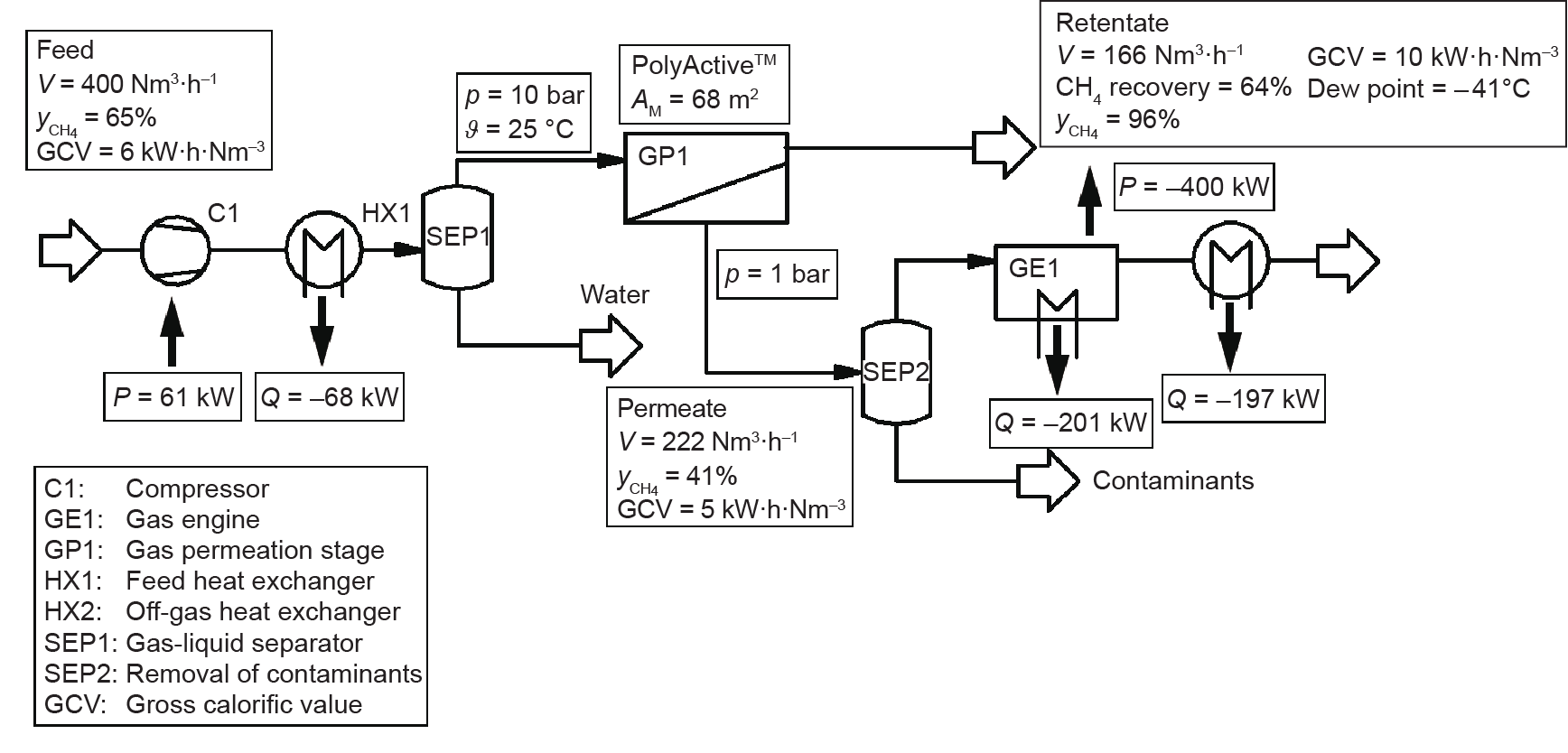
Fig. 9. Design study showing a combined CO2 separation from biogas using single-stage membrane gas separation and onsite energy generation [36]. V: volumetric flow rate; yCH4 : mole fraction of CH4; p: pressure; ϑ: temperature; AM: membrane area; P: power; Q: duty.
In addition to the investigations presented here, several other applications are possible. For example, PolyActive™ multilayer composite membrane was installed in a small-scale, 100 mm diameter envelope-type membrane module aimed at the separation of CO2 from a reaction product containing ethylene, methane, and nitrogen [36]. Such separations are expected to become more important as the chemical industry moves toward alternative routes for the production of base chemicals, such as the oxidative coupling of methane [48]. Another possible application is the separation of CO2 from H2. This separation is even more important when the increasing demand for H2 in a changing energy and raw material supply scenario is taken into consideration. The great potential of PolyActive™ multilayer composite membrane for this process rests on the preferential permeation of CO2, leaving H2 on the high-pressure side of the process. Franz [49] examined this separation in the course of her research work on hydrogen production with micro algae.
《5.Conclusions》
5.Conclusions
In recent years, a CO2-selective TFCM employing the block copolymer PolyActive™ for the separation layer was developed and continuously improved. The flat-sheet membrane exhibits CO2 permeances of up to 4 m3(STP)·(m2·h·bar)−1 at CO2 /N2 selectivities of > 55 at 20 °C. Hence, it is one of the best membranes for CO2 separation from flue gas that has been reported to date. The membrane can be manufactured in 100 m2 scale with reproducible separation performance. Pilot plant trials showed its applicability for various separation tasks, such as separating different flue gases and biogas. In addition to these applications, PolyActive™ multilayer composite membrane is useful for separating CO2 from H2 or other gaseous mixtures, an application that may gain importance given the world’s changing raw material and energy supply scenarios.
《Acknowledgements》
Acknowledgements
Groundbreaking work in the initial development of the PolyActive™ multilayer composite membranes was carried out within the scope of the Helmholtz Alliance Mem-Brain funded by the Helmholtz Association of German Research Centers. The authors gratefully acknowledge the funding given by the German Federal Ministry for Economic Affairs and Energy to finance the research project METPORE II (03ET2016). In addition, the authors would like to thank the METPORE II project partners as well as SSC Strategic Science Consult GmbH and BORSIG Membrane Technology GmbH.
《Compliance with ethics guidelines》
Compliance with ethics guidelines
Torsten Brinkmann, Jelena Lillepärg, Heiko Notzke, Jan Pohlmann, Sergey Shishatskiy, Jan Wind, and Thorsten Wolff declare that they have no conflict of interest or financial conflicts to disclose.


 京公网安备 11010502051620号


