《1. Introduction》
1. Introduction
The stay cables of cable-stayed bridges are subject to aerodynamic excitation forces due to their oblique attitude against the wind. They sometimes exhibit large-amplitude vibration, not only under rain conditions but also under dry (no rain) conditions. The former is referred to as rain-wind-induced vibration (RWIV) [1] and the latter is referred to as dry galloping (DG); there are many studies [2,3] on their mechanisms. It is understood that both vibra- tions are related to the inherent instability of inclined cables; in particular, RWIV is caused by water rivulets running down the cable surface and DG is caused by the suppression of Karman vortices in the critical Reynolds number range together with an axial flow behind the cable. Considering their vibration mechanisms, some surface-modification cables were developed that included spiral protuberances [4], longitudinally parallel protuberances [5], and indentations [6]. In order to further improve cable performance, a new type of surface-modification cable with prefabricated spiral protuberances was recently developed [7]. For a surface modification, attention must be paid to the increase in the drag force coefficient (CD ). The newly developed spiral protuberance cable was tested for CD in an independent study and it was confirmed that the CD of the new cable was as low as that of the indented cable [7]. In this study, using a renovated wind tunnel with a rain simulator system, the performance of two
surface-modification cables, including the spiral protuberance and the indented cables, was investigated.
《2. Experimental facility》
2. Experimental facility
The RWIV was reproduced in the wind-tunnel facility with a rain simulator at the Yokohama National University. An old wind tunnel was renovated by replacing a working section and equipping water spray nozzles, as shown in Fig. 1. The working section with the rain simulator was placed just at the wind-tunnel exit, which was 1.3 m in width and 1.3 m in height. Water was sprayed from water spray nozzles on the ceiling of the working section, as shown in Fig. 2. The maximum wind speed was about 20 m·s -1 .
《Fig. 1》

Fig. 1. Rain-wind simulator.
《Fig. 2》

Fig. 2. Working section and rain simulator.
A cable model of 1.5 m in effective length was placed in the working section using a pipe frame, as shown in Fig. 3. The model was supported by coil springs with one vertical degree of freedom. The coil springs were attached in the direction normal to the cable axis. The flow yaw angle and the vertical angle could be adjusted by rotating and lifting/lowering one side of the pipe frame, respectively. There are some discussions on the “end effect” of a cable model. In this study, a whole cable model without end-effect treatment was exposed to a wind flow. This was done to avoid unknown effects due to the end-effect treatment, as the main objective of this study was a comparison among different cases.
The response of the model was measured by accelerometers placed on both ends of the model. Model vibration was measured with a sampling frequency of 100 Hz. The natural frequency of the model was 0.8–1.0 Hz, depending on the test cases. 《Fig. 3》

Fig. 3. Cable model setup.
《3. Reproduction of RWIV》
3. Reproduction of RWIV
In order to check the performance of the wind tunnel and rain simulator, a circular cable model of a 1.5 m long polyethylene pipe was tested to reproduce RWIV. Two different diameter models of 110 mm (D110 mm) and 158 mm (D158 mm) were tested. Figs. 4 and 5 show the response amplitude versus the wind speed for the D110 mm and D158 mm cases, respectively. The Scruton number (Sc) was set to small, from 3 to 11, in order to generate RWIV easily, as described in the figure caption. In this study, Sc is defined as follows:

where m is the mass per unit length, d is the structural damping of the logarithmic decrement, p is the air density, and D is the model diameter. Due to the model support mechanism, damping in small vertical angle cases tends to be small; therefore, Sc in those cases is relatively small. The vertical angle (a) was changed to 40° and 25° for the D110 mm case, and to 40°, 25°, and 9° for the D158 mm case. The flow yaw angle (b) was changed to 0°, 15°, 30°, 45°, and 60°.
《Fig. 4》
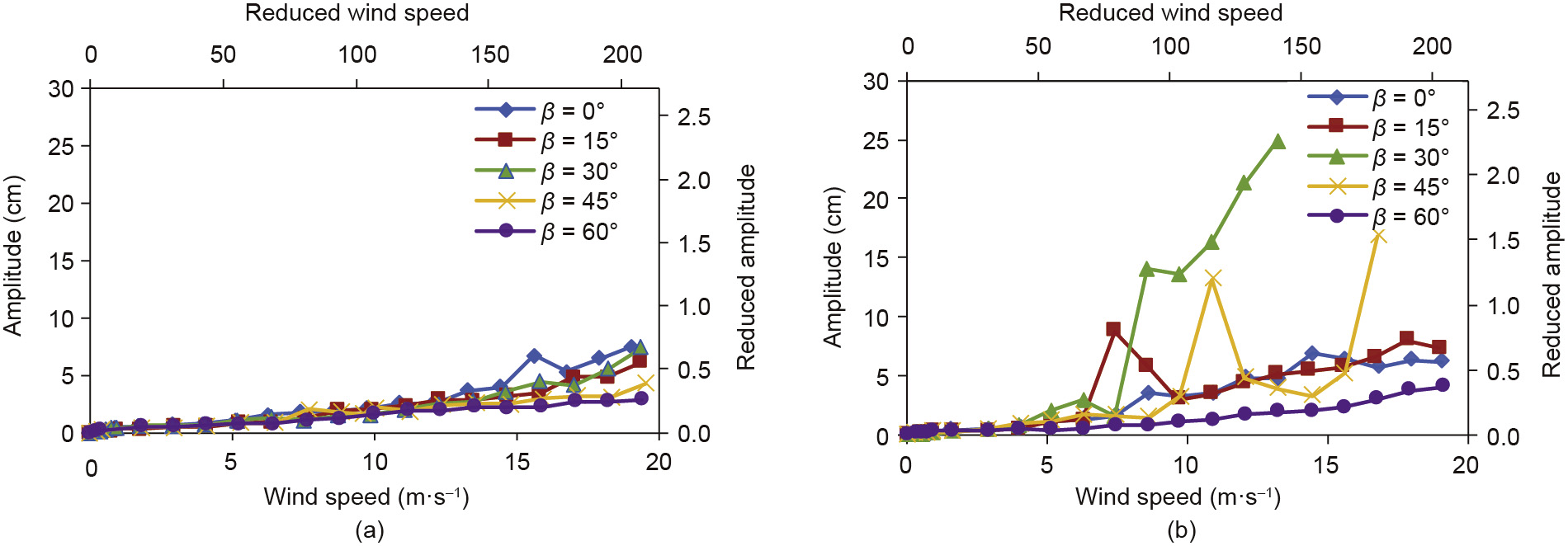
Fig. 4. Response amplitude of circular cable model vs. wind speed under rain conditions (D110 mm). (a) α = 40° (Sc = 10–11); (b) α = 25° (Sc = 9–11).
《Fig. 5》

Fig. 5. Response amplitude of circular cable model vs. wind speed under rain conditions (D158 mm). (a) α = 40° (Sc = 7–9); (b) α = 25° (Sc = 6–9); (c) α = 9° (Sc = 3–4).
Large-amplitude RWIV took place only at α = 25° with β = 15°, 30°, and 45°, as shown in Figs. 4 and 5. It did not take place at a = 40° and 9°. Measurement was stopped when the vibration amplitude reached around 25 cm in order to prevent supporting system failure. This large-amplitude vibration was observed in the case of α = 25° with β = 30°. On the other hand, vibration increased considerably at the wind speed of 16 m·s-1, even more after the first peak at 11 m·s-1 in the case of D110 mm, and α = 25° with β = 45°. The first peak was RWIV, while the second large vibration was caused by the mechanism of DG, since no water rivulet formed on the cable surface.
During RWIV, a thin-film-like water rivulet formed on the cable surface. The rivulet vibrated in the circumferential direction synchronously with the cable vibration. The characteristics of the RWIV and rivulet are quite similar to those observed in past studies [8]. The rain intensity during RWIV was 40–60 mm·h-1, which was heavy. The rain intensity was adjusted such that RWIV took place in this study. Although the effect of the rain intensity must also depend on cable length, a detailed discussion is not made here.
《4. Response of surface-modification cables under rain conditions》
4. Response of surface-modification cables under rain conditions
As already described, several surface-modification cables were developed for RWIV countermeasures. In this study, two types of surface-modification cable—spiral protuberance [7] and indented [6] cables—were tested for RWIV, as shown in Fig. 6.
The indentation geometry followed the prototype pattern (Fig. 6(c)) that was adopted for the Tatara Bridge, which was the first to use indented cables. Eight indented patterns are placed equally and circumferentially on the surface. The depth of the indentation is 1 mm.
《Fig. 6》
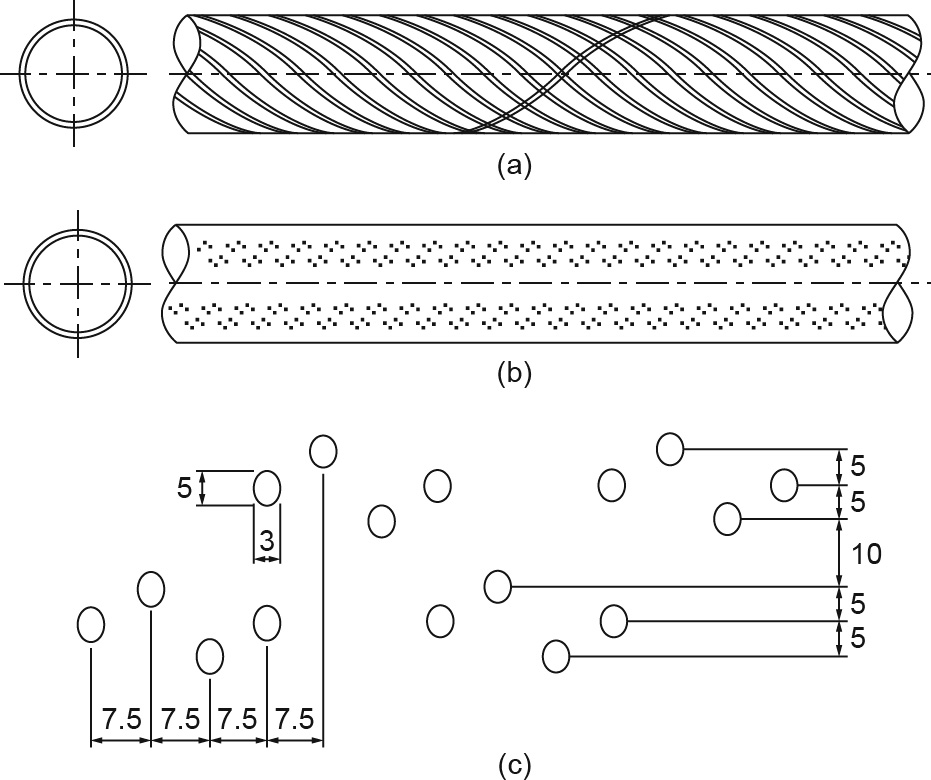
Fig. 6. Surface-modification cables. (a) Spiral protuberance cable; (b) indented cable; (c) dimensions of indentation (unit: mm).
In addition, some parameter tests for the spiral protuberance cables were conducted. The models were supported in the same manner as in the circular model case, as shown in Fig. 7. The Sc condition was also nearly the same as that of the circular model case, which is shown in the figure for each case.
《Fig. 7》
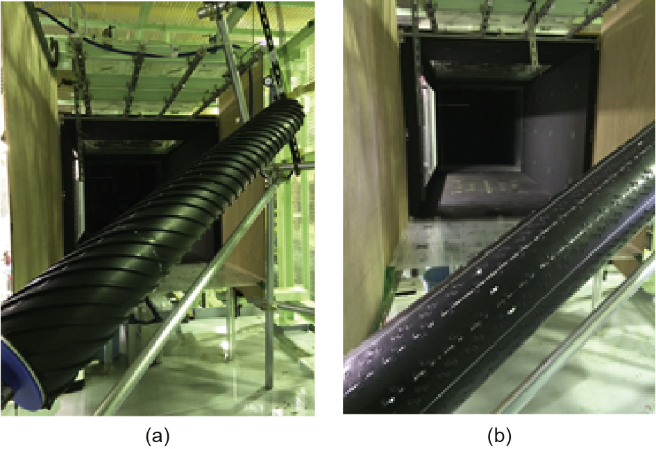
Fig. 7. Setup of surface-modification cable models. (a) Spiral protuberance cable;(b) indented cable.
《4.1. Response characteristics of spiral protuberance and indented cables》
4.1. Response characteristics of spiral protuberance and indented cables
Figs. 8 and 9 show the response amplitude of the spiral protuberance and of the indented cables with the diameter of 158 mm, respectively, under rain conditions. RWIV took place in the case of the indented cable at some angles. It was observed that some water rivulets passed over the indentations during RWIV. However, it is understood that the RWIV observed in this study was due to Sc being much smaller than in a full-scale condition. On the other hand, the spiral protuberance cable did not exhibit RWIV for all cases, but only for cases with small-amplitude random vibration.
《Fig. 8》

Fig. 8. Response amplitude of spiral protuberance cable model vs. wind speed under rain conditions (D158 mm). (a) α = 40° (Sc = 9); (b) α = 25° (Sc = 5–12); (c) α = 9° (Sc = 4).
《Fig. 9》

Fig. 9. Response amplitude of indented cable model vs. wind speed under rain condition (D158 mm). (a) α = 40° (Sc = 8–9); (b) α = 25° (Sc = 5–8); (c) α = 9° (Sc = 3–4).
《 4.2. Effects of spiral protuberance dimensions on response》
4.2. Effects of spiral protuberance dimensions on response
The dimensions of the spiral protuberance were decided based on a past study [7]. The original dimensions were optimized so as to keep Co low and to prevent water rivulet formation at the same time. The basic dimensions are: 12 circumferential protuberances of 5 mm in height and 7.5 mm in width, with a spiral angle of 27°. However, the effects of the spiral protuberance dimensions were only confirmed in a wind tunnel under dry (no rain) conditions for DG at that time. Therefore, it is desirable to confirm the effects of the spiral protuberance dimensions under rain conditions for RWIV.
A significant effect of the number of spiral protuberances is not observed as long as the 5 mm height is kept, as shown in Fig. 10(a). However, a slight increase in the amplitude is found in the case of two protuberances. In order to investigate the minimum height of the spiral protuberance, dimensions of 2 mm and 3 mm height were tested, while keeping 12 protuberances and a width of 7.5 mm. It was found that the 2 mm height case increased the vibration amplitude significantly, as shown in Fig. 10(b).
Further investigation on the effects of height and number of spiral protuberances was conducted. The 2 mm height increased the RWIV amplitude more than the basic 5 mm height case, even with 12 protuberances, as shown in Fig. 10(c). For 3 mm height, a decrease in spiral protuberance number affected the vibration amplitude, as shown in Fig. 10(d). The case of 12 protuberances only prevented an increase in the RWIV amplitude. Therefore, if the number of spiral protuberances is kept at the original number of 12, a protuberance height of 5 mm is desirable.
《Fig. 10》

Fig. 10. Response amplitude of spiral protuberances cable model vs. wind speed for different spiral protuberance dimensions under rain condition (D158 mm, α = 25°, β = 30°). (a) Number of spiral protuberances (5 mm height); (b) size of spiral protuberance (height × width) (12 protuberances); (c) number of spiral protuberances (2 mm height); (d) number of spiral protuberances (3 mm height).
《5. DG of surface-modification cables》
5. DG of surface-modification cables
In addition to RWIV, DG was tested for the surface-modification cable model. Fig. 11 shows the response amplitude of the spiral protuberance cable model under dry (no rain) conditions, compared with the circular cable model case.
《Fig. 11》
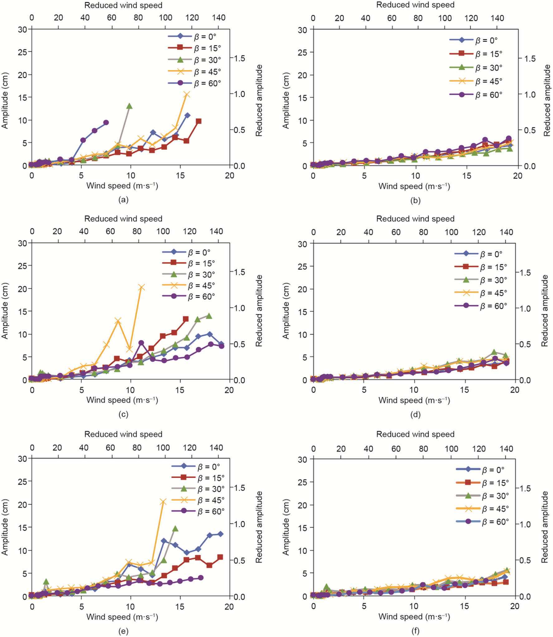
Fig. 11. Response amplitude vs. wind speed under dry (no rain) conditions (D158 mm). (a) Circular, a = 40° (Sc = 7–9); (b) spiral protuberance, a = 40° (Sc = 9); (c) circular, a = 25° (Sc = 6–9); (d) spiral protuberance, a = 25° (Sc = 5–12); (e) circular, a = 9° (Sc = 3–4); (f) spiral protuberance, a = 9° (Sc = 4).
The cause of DG was explained mainly in terms of the critical Reynolds number flow regime and the axial flow behind an inclined cable [3]. However, a large-amplitude vibration was also observed under dry (no rain) conditions at the subcritical range for the inclined stay cables of a full-scale bridge [2]. Therefore, this study also deals with divergent large-amplitude vibration under dry (no rain) conditions as DG in a broad sense.
The circular cable model exhibited large-amplitude DG, particularly with the flow angles of β = 30° and 45°. However, these vibrations occurred with a low Sc of up to 10, which is relatively lower than that of full-scale cables. It was confirmed that largeamplitude DG was suppressed below the reduced amplitude of 0.5 with an increase in Sc to around 60. On the other hand, the spiral protuberance cable model was completely stable and exhibited only small-amplitude random vibration.
《6. Conclusions》
6. Conclusions
In this study, the performance of two kinds of surfacemodification cables was investigated using a renovated wind tunnel with a rain simulator system. The following results were obtained.
RWIV was successfully reproduced in the wind tunnel. It was also observed that the water rivulet on the cable surface vibrated in the circumferential direction synchronously with the cable vibration. These characteristics coincide well with past studies.
The indented surface-modification cable showed good performance for both RWIV and DG, except under some particular conditions. However, the increase in Sc can suppress vibrations. The spiral protuberance cable showed thoroughly good performance for both RWIV and DG.
Finally, the effects of the spiral protuberance dimensions were clarified. Certain limits in the dimensions, such as height and protuberance number, are required in order to suppress RWIV.
《Compliance with ethics guidelines》
Compliance with ethics guidelines
Hiroshi Katsuchi, Hitoshi Yamada, Ippei Sakaki, and Eiichi Okado declare that they have no conflict of interest or financial conflicts to disclose.


 京公网安备 11010502051620号


