

《1.Introduction》
1.Introduction
Passive safety technology has developed rapidly and has become more mature in recent years, with the airbag system playing an important role in the protection of vehicular passengers. Traffic accident statistics show that using an airbag system alone can reduce the mortality rate in a collision by 32%, while using both an airbag system and a seatbelt can reduce the mortality rate by 67% [1]. However, an airbag gas generator will produce a tremendous amount of energy when it explodes, which brings a high risk of injury to occupants. One hazard is that the shell of a gas generator will easily deform and break due to the effect of high-temperature and high-pressure gas. As a result, the metal pieces may fly at lethal speeds into the head and chest of the vehicular occupant, which is one of the main reasons for the widespread Takata airbag recalls. Another hazard is that an airbag has a very large internal pressure, resulting in a strong impact force in the process of expansion. Occupants may have to bear this high impact force, which can cause fatal injuries, if they come into contact with the airbag before it is fully deployed [2,3]
Many studies have been carried out to reduce the risk of injury caused by airbag deployment, with positive results in two aspects: improving the gas generant and improving the mechanism of the gas generator. In efforts to improve the gas generant, some studies explored low-temperature and highly stable gas generants, including guanidine nitrate (GN) and ammonium nitrate (AN) formulations. Mendenhall and Taylor [4] added a quantity of metal aminotetrazole hydroxide to the GN gas generant formulation, which increased the burning rate by ensuring stable combustion and a low burning temperature. Halpin and Burns [5] improved the stability of the AN gas generant formulation by adding a little fumed silica. With regard to improving the mechanism of the gas generator, studies have mainly focused on a double-stage gas gen-erator, because it can release the energy of the gas generant twice. Wu [6] utilized a computer simulation method to study a double-stage gas generator airbag; the results showed that the airbag would have a better effect on occupant protection. Zhang et al.[7] set the parameters of a two-stage airbag and carried out a sled test, showing that the airbag could effectively reduce the risk of injury to the chest of female passengers.
Based on the design concept of a new automotive interior and occupant restraint system using a tubular airbag [8,9], this paper presents the design of a new tubular airbag from the perspective of reducing the dosage of gas generant; the aim is to decrease the explosion energy and thus lower the risk of injury to occupants caused by the airbag. By using multiple airbag tubes to form an energy-absorption space, the tubular airbag can substantially reduce the static volume yet ensure closely effective expansion volume compared with an ordinary airbag. Based on this premise, the stiffness and the protection performance of the tubular airbag are explored by computer simulation using different numerical dummies. Finally, a multi-objective optimization of the 50th percentile dummy is conducted. The results show that the dosage of gas generant is reduced and the airbag provides a good protective effect.
《2. Design of the new tubular airbag》
2. Design of the new tubular airbag
《2.1 Functional design of the airbag》
2.1 Functional design of the airbag
The design concept of the tubular airbag features multiple air-bag tubes that are used to form an energy-absorption space while relying on its own structural characteristics to withstand external forces. The new airbag will have a similar effective expansion volume as an ordinary airbag, which enables it to have a lower dosage of gas generant and lower explosion energy. The airbag maintains a high pressure due to its low-porosity material and by setting the vent hole at an appropriate location, which gives the tubular airbag better robustness than an ordinary airbag. In the future, a new process of seamless integration can be developed for mass production, which can ensure high quality in the design and manufacture of the tubular airbag. This paper mainly focuses on the feasibility of reducing the explosion energy of the new tubular airbag, ensuring that the airbag has an effective expansion volume with a smaller dosage of gas generant, and simultaneously ensuring a stable protective effect.
《2.2. Structural design of the airbag》
2.2. Structural design of the airbag
The new tubular airbag has a circular truncated cone shape and contains ring-shaped airbag tubes in the upper and lower parts, folded airbag tubes in the middle part, and two cushions. There are two ring-shaped airbag tubes at the bottom, three ring-shaped airbag tubes on the top, and four long airbag tubes in the middle part. Each tube in the middle connects the upper and lower parts from the bottom center of tubular airbag. The structural diagram of the new tubular airbag is shown in Fig. 1. The diameter of all the tubes is 38 mm; the diameters of the tube axes at the bot-tom are 160 and 290 mm, respectively; the corresponding diameters on the top are 147, 325, and 507 mm, respectively; and the overall height of the airbag is 330 mm. The upper and lower parts are sewed with a soft cushion.
《Fig. 1》
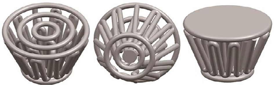
Fig. 1. The structural diagram of the new tubular airbag.
《2.3 Description of the process of airbag deployment》
2.3 Description of the process of airbag deployment
When the new tubular airbag is inflated, gas from the gas generator enters the gas storage chamber that connects the heads of the four middle tubes. Gas also enters the tubes and makes the airbag deploy rapidly to reach the designed thickness value in the Z direction (height direction), and then continues to inflate along the tubes so that the airbag expands in the X and Y directions to meet the design requirements. This design quickly spreads the gas energy to the XY plane and thus reduces the risk of injury to occupants during the deployment of the airbag.
《3. Protection performance analysis of the new tubular airbag》
3. Protection performance analysis of the new tubular airbag
This study focuses on a preliminary analysis of the driver protection that is provided by the new tubular airbag. An investigation of the protection provided to other occupants will be conducted in the future.
《3.1 Establishment and validation of the restraint system model》
3.1 Establishment and validation of the restraint system model
According to the size and physical properties of each part of the restraint system utilized in a Toyota Yaris (2006), a simplified driver-restraint system was established using HyperMesh, Primer, and LS-DYNA to improve calculation efficiency. The model con-sisted of a seat, a three-point seatbelt, an airbag, a steering wheel, and the floor. The corresponding connection modes were defined among the components in order to obtain physical properties that match the situation in a real vehicle.
The one-dimensional and two-dimensional elements of the three-point seatbelt model were simulated by using the keywords *MAT_SEATBELT and *MAT_FABRIC, respectively, and the re-tractor was defined by the keyword *ELEMENT_SEATBELT_RETRACTOR [10]. In addition, the loading and unloading curves of the re-tractor and the seat belt material were defined, thus making the physical properties of the sea tbelt more accurate.
For the finite element model of the airbag, the keyword *AIRBAG_HYBRID_JETTING was adopted in order to better simulate the airbag deployment and inflation characteristics. Next, the Belytschko-Tsay membrane element and the material MAT34 in LS-DYNA were chosen. The physical parameters of the airbag are shown in Table 1.
《Table 1》
Table 1 Physical parameters of the airbag.

In the process of establishing and verifying the restraint system, the Hybrid III dummy developed by Livermore Software Technology Corporation was used, and the dummy posture was adjusted to keep the dummy in a normal driving position. The contact surface between the dummy and the other components of the vehicle should be correctly defined in order to obtain the correct contact force [11], so the keyword *CONTACT_AUTOMATIC_SURFACE_TO_ SURFACE was defined for the contact characteristics between the dummy and the other components. The restraint system model that was established is shown in Fig. 2.
According to the frontal impact test results of the Toyota Yaris model, which was conducted by the United States New Car Assess-ment Program (US NCAP) at a speed of 56.3 km h-1, the filtered acceleration curve was obtained (Fig. 3), and then loaded into the established restraint system. The validity of the restraint system model was verified by adjusting the contact characteristics and friction coefficient.
《Fig. 2》

Fig. 2. The restraint system model.
《Fig. 3》

Fig. 3. Acceleration curve of vehicle. g = 9.8 m·s-2.
《3.2 Establishment and verification of the tubular airbag finite element model》
3.2 Establishment and verification of the tubular airbag finite element model
A three-dimensional model of the new tubular airbag was created using the modeling software UG; the model was then imported into Altair HyperMesh software to generate meshes, with a total of 37 921 nodes and 40 123 elements.
Liu et al. [12] proved that using an unfolded or partially folded airbag model did not significantly affect the validity of the simulation results, so this model could be used for belted occupants in a normal position. In the process of folding the airbag, the initial metric method [13] was adopted, and the airbag was simply scaled to obtain the initial meshes. The keyword *AIRBAG_REFERENCE_ GEOMETRY was used to define the fully expanded finite element model as the reference mesh. The element type, material, and key-word used to control the airbag deployment in the model were the same as those defined in the restraint system. Furthermore, the contact boundary of the airbag could be detected during the simulation process with the help of the keyword *CONTACT_AIRBAG_ SINGLE_SURFACE, which made the process of deployment more accurate and stable.
In order to verify the accuracy of the finite element model of the airbag, a prototype of the new tubular airbag was trial-produced; a static deployment experiment was then onducted sing a high-pressure inflator pump. The inflator, which could generate gas with a pressure of 0.6 MPa, connected the air intake at the bottom of the new tubular airbag. The process of airbag deployment was recorded with a high-speed camera that could take 1000 frames per second, for a comparison with the computer simulation results. It must be emphasized that the parameters of the simulation and those of the experiment were controlled to be similar.
《3.3 Preliminary study on the protective effect of the tubular airbag on the driver》
3.3 Preliminary study on the protective effect of the tubular airbag on the driver
Because the stature and weight of drivers vary in a wide range, the stiffness and the protection performance of the tubular airbag are critical factors for different drivers when using less gas gener-ant to deploy the airbag. In order to investigate the aforementioned issues, the 5th, 50th, and 95th percentile dummies (representing a small woman, an average man, and a large man, respectively) were chosen to represent occupant diversity with the established restraint system. Corresponding simulation experiments on an ordinary airbag were also carried out for comparison. The vent areas of an ordinary airbag and of the tubular airbag were set up as 1800 and 600 mm2, respectively. The physical parameters of other parts of the airbags were controlled to be the same as each other in order to compare the similarities and differences more accurately. A common gas mass flow rate curve for the simulation comparison is shown in Fig. 4.
《Fig. 4》
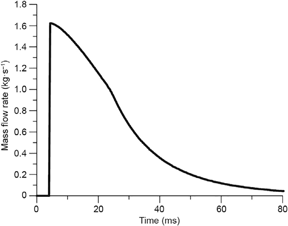
Fig. 4. Gas mass flow rate curve.
To evaluate the protective effect of the tubular airbag under different dosages of gas generant, two additional sets of simulation experiments were performed with a gas mass flow coefficient of 0.4 and 0.7, respectively. That is to say, four sets of simulation experiments were carried out corresponding to each type of dummy, and the protection of the head and chest was emphatically explored.
《4. Optimization analysis based on the 50th percentile dummy》
4. Optimization analysis based on the 50th percentile dummy
To further explore the potential of the tubular airbag in driver protection, an optimization analysis of the restraint system equipped with the tubular airbag was carried out, and the results were compared with the previous results before optimization.
《4.1 Selection of the objective function》
4.1 Selection of the objective function
The head injury criterion (HIC) and Chest G values are of critical importance in defining the degree of injury. The calculation method for the HIC value is shown in Eq. (1), where the time interval adopted in the equation is 36 ms. The rationale for the 3 ms acceleration criterion that was used to characterize the effect of the restraint system on the chest is that the acceleration load of the human chest cannot exceed 60g (g = 9.8 m s-2) when the duration exceeds 3 ms.

where a(t) is the resultant acceleration of the head, t1 and t2 are the moments that maximize the HIC value, and t2- t1 equals 36 ms in this paper.
In order to reasonably evaluate the contribution of head and chest acceleration to driver injury, the US NCAP index Pcomb [14] was chosen as the objective function, which could reflect the probability of passengers being injured above the Abbreviated Injury Scale (AIS) 4. The equations were as follows:

where Phead and Pchest are the probabilities of passengers’ head and chest being injured above the AIS 4, respectively. They can be calcu-lated by

《4.2 Selection of design variables》
4.2 Selection of design variables
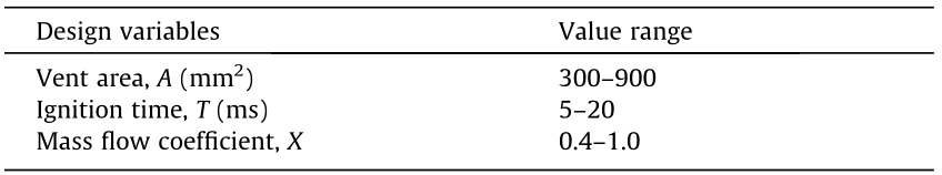
As this paper focuses on the stiffness and protective effect of the tubular airbag when reducing the dosage of gas generant, the vent area, ignition time, and mass flow coefficient were selected as optimization parameters. The ranges of design variables and parameters are shown in Table 2.
《Table 2》
Table 2 Design variables and value range
《4.3 Design of experiments and construction of a surrogate model》
4.3 Design of experiments and construction of a surrogate model
Referring to Ref. [15], a Latin square design of the selected three parameters was conducted using the multi-objective optimization software modeFRONTIER. The experimental design matrix was obtained after setting the number of data groups to 60. The LSDYNA software was subsequently used to simulate the output of head and chest injuries according to the parameters of the experimental matrix. Next, simulation data of the 60 groups were saved as a form file and imported into modeFRONTIER, and the DACEKriging method was used to construct a surrogate model that was derived from the global model and the local deviation represented by the stochastic process [16].
《4.4 Optimization calculation and analysis》
4.4 Optimization calculation and analysis
The multi-objective genetic algorithm II (MOGA-II) optimization method was used in this study in order to simultaneously minimize the HIC and 3 ms chest acceleration values. The genetic algebra of the MOGA-II method was set to 100, and the mathematical expressions of this problem were as follows:

《5. Results and discussion》
5. Results and discussion
《5.1 The new design of the tubular airbag》
5.1 The new design of the tubular airbag
As a result of the multiple-tube structure used by the tubular airbag, the ultimate effective expansion volume is 50 L while the static volume is about 20 L. This difference is sufficient to effectively reduce the dosage of gas generant and simultaneously guarantee enough stiffness.
《5.2 Validation of the restraint system and tubular airbag》
5.2 Validation of the restraint system and tubular airbag
For the restraint system, the peak value and the variation ten-dency of the injury index curve were proven to be similar in the results obtained by both the experimental simulation and real vehicle testing, as shown in Fig. 5. Therefore, the restraint system model was validated.
《Fig. 5》

Fig. 5. Comparisons of the injury index curves of the simulation and the test. (a) Comparison of head acceleration; (b) comparison of chest acceleration.
For the tubular airbag, comparisons of the corresponding moments during deployment are shown in Fig. 6. Due to the limitation of the computer simulation algorithm, the airbag approached its final shape prior to being inflated, which accounts for the deviations in the shapes of deployment. However, the deployment processes of the simulation and of the test were basically similar, and the validity of the airbag finite element model was preliminarily verified.
《Fig. 6》
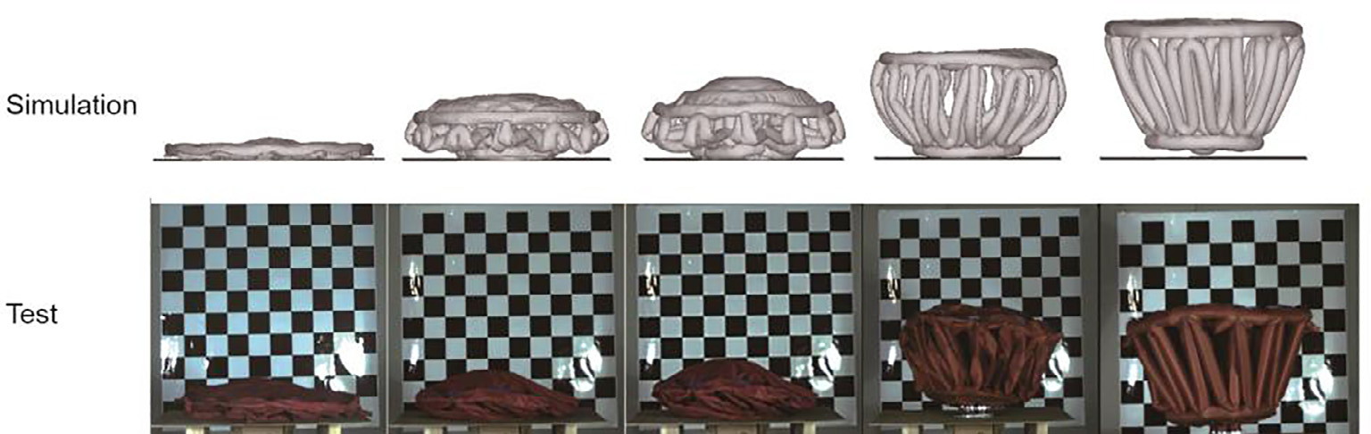
Fig. 6. Comparisons of the airbag deployment of the simulation and the test.
《5.3 Preliminary investigation of the tubular driver airbag》
5.3 Preliminary investigation of the tubular driver airbag
Considering intuitive observation of the dynamic response, the responses of the 50th percentile dummy are shown in Fig. 7 as an example. Based on the acceleration values measured in each direction in the simulation, the resultant acceleration curves of the head and chest were obtained, and acceleration comparisons of different dummies could be observed, as shown in Fig. 8.
《Fig. 7》

Fig. 7. The responses of the 50th percentile dummy.
《Fig. 8》

Fig. 8. Acceleration comparisons of different dummies: Head acceleration comparisons of the (a) 5th percentile dummy, (b) 50th percentile dummy, and (c) 95th percentile dummy; chest acceleration comparisons of the (d) 5th percentile dummy, (e) 50th percentile dummy, and (f) 95th percentile dummy.
The resultant acceleration of the head is an important index to measure the degree of injury [17]. For the 5th percentile dummy, the head acceleration curves in four sets showed similar trends based on simulation output, while the acceleration curve of the ordinary airbag reached the peak value earlier, as shown in Fig. 8(a). When the mass flow coefficients of the two kinds of air-bags were equal at 1.0, the peak value of the tubular airbag was smaller. In addition, as the mass flow coefficients of the tubular air-bag decreased to 0.7 and 0.4, the peak value declined accordingly, which indicated that less gas generant could soften the impact effect of the airbag on the occupants. This phenomenon was prob-ably due to the smaller stature and weight of the 5th percentile dummy. Using less gas generant could ensure enough airbag stiff-ness to provide an appropriate restraint force, while weakening the impact effect for good protection efficiency. For the 50th and 95th percentile dummies, it can be seen from Fig. 8(b) and Fig. 8(c) that the protective effect of the tubular airbag was almost the same when the mass flow coefficients were 0.7 and 1.0, respectively. These peak values were both smaller than that of the ordinary air-bag. However, the curve of the tubular airbag had a rather high peak value when the mass flow coefficient was 0.4, which showed that the stiffness of the tubular airbag failed to achieve the desired performance for these two types of body stature. In other words, a gas generant reduction of up to 60% could not allow the airbag to provide sufficient restraint force. Nevertheless, when the gas generant reduction was in a reasonable range (e.g., 30%), the tubular airbag could still achieve a good protective effect.
Resultant chest acceleration is a significant criterion to evaluate chest injury. For the 5th percentile dummy, when the mass flow coefficients of the tubular airbag were 1.0, 0.7, and 0.4, respectively, the curves were similar to each other with a low acceleration peak, as shown in Fig. 8(d). Comparatively, the acceleration caused by the ordinary airbag was larger, and the protective effect was correspondingly poorer. For the 50th and the 95th percentile dummies, the curves of both airbags had similar trends. When the mass flow coefficient of the two airbags was 1.0, the value of the curves was basically the same, resulting in a good protective effect. As the mass flow coefficient of the tubular airbag decreased to 0.7 and 0.4, the peak value of acceleration was also lower than that of the ordinary airbag, as shown in Fig. 8(e) and Fig. 8(f).
To further explore the quantitative differences between the ordinary airbag and the tubular airbag in terms of protective effect, HIC and 3 ms chest acceleration values were used as measuring standards. The injury data in Table 3 were calculated by processing the acceleration curves shown in Fig. 8. For head injury, when the mass flow coefficients of the tubular airbag were 0.4 and 0.7, the HIC values for the 5th percentile dummy were 322.92 and 418.55, respectively, which were lower than the two airbags when the mass flow coefficient was 1.0. When the mass flow coefficient was 0.4 for the 50th percentile and 95th percentile dummies, the HIC values reached 1026.07 and 924.81, respectively, due to the rather high peak value. With regard to chest injury, the Chest G values of the tubular airbags were similar for the three mass flow coefficients for each dummy, and these values were lower than those of the ordinary airbag. Therefore, the results of the quantitative and qualitative analysis were consistent with each other.
《Table 3》
Table 3 The injury values of dummies under different mass flow coefficients.
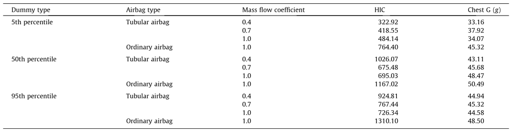
According to the qualitative and quantitative analysis results, it is possible for the 5th percentile dummy to have the dosage of gas generant reduced by 60% and meet the regulatory requirements for the HIC and 3 ms chest acceleration values. The dosage of gas generant can be reduced by at least 30% for the 50th and 95th percentile dummies and achieve the desired protective effect.
《5.4 Optimization analysis》
5.4 Optimization analysis
The results showed that the average standard errors of the HIC and 3 ms chest acceleration surrogate models were 1.5 ×10⁻¹³ and 3×10-14, respectively, while the R2 values of the two models both equaled 1, indicating a high degree of fit. Based on the above analysis, the surrogate model was able to accurately predict the response value in the design space, and thus replaced LS-DYNA as the basis of optimization.
The Pareto solution set of the objective functions in the design space was obtained by software calculation, as shown in Fig. 9. With regard to the multi-objective optimization problem, goodresults for all objective functions cannot be guaranteed [18]. Many points on the front of the Pareto solution set can be used as the solution to the problem, and these points need to be chosen artificially. Therefore, the Pcomb function was used to obtain the Pareto solution set in this paper. Optimization results showed that the Pcomb value was approximately 0.12, the corresponding HIC value of the head was 632.8, and the 3 ms chest acceleration value was about 41.4. The optimal parameter values from the optimization results were then put into LS-DYNA for calculation. The results showed that the Pcomb value was 0.13 with 8.5% error, the HIC value was 671.1 with 5.7% error, and the 3 ms chest acceleration value was 42.33 with 2.2% error. On the basis of the above data, all errors were determined to be within a reasonable range, which further confirmed the accuracy of the surrogate model. The optimized results were then compared with the previous simulation results, as shown in Table 4. It can be seen from the results that Pcomb was reduced by 22%, and that the protective effect on the driver was obviously improved after optimization. In addition, the optimal mass flow coefficient in the design space was 0.68, which showed that the dosage of gas generant could be reduced, thus reducing the static volume while still achieving better driver protection. By extending the design space, better parameter values could be explored. The above results show that the tubular airbag has great potential in the field of occupant protection.
《Fig. 9》

Fig. 9. The Pareto solution set of the new tubular airbag.
《Table 4》
Table 4 Comparisons of the tubular airbag before and after optimization.

《5.5 Limitations and future work》
5.5 Limitations and future work
Some limitations in the present study still exist. First, commercial software was used to investigate the protective effect, whereas future work will focus on experiments on the tubular airbag product to examine the safety performance. Second, the folded pattern of the new tubular airbag was not considered, and the static deployment experiment was not conducted in accordance with regulations. Future work will focus on improving the folded pattern and the shape optimizations of the tubular airbag. Third, this study only focused on the protection of drivers. In future studies it will be necessary to investigate the safety performance of the tubular airbag for other vehicular occupants. Last, one requirement in the design of the ordinary airbag is to balance the performances between small and heavy occupants; therefore, we assumed that the potential for reducing the dosage of gas of the ordinary airbag was not as big as that of the tubular airbag for small occupants. Future works are needed to prove our assumption.
《6. Conclusions》
6. Conclusions
The research described in this article was done in an effort to find a solution to the problem of excessive energy being released during airbag ignition. The design of a new tubular airbag was explored, its stiffness and protection performance was evaluated, and an optimization analysis was undertaken. Conclusions are as follows.
(1)The designed airbag is a circular truncated cone shape, and the main body contains multiple airbag tubes to form an energyabsorption space. The static volume is reduced substantially to 1/3 of the static volume of an ordinary airbag. However, the effective expansion volume is basically the same as that of an ordinary airbag. This allows for a decrease in the dosage of the gas generant and results in less explosion energy, thus lowering the risk of injury to occupants caused by the airbag’s deployment.
(2)Three different percentile dummies were chosen in the simulation process using the tubular airbag and an ordinary airbag. Based on the simulation results, it is possible for the 5th percentile dummy to have the dosage of gas generant reduced by 60% and meet regulatory requirements for HIC and 3 ms chest acceleration values. The dosage of gas generant can be reduced by at least 30% for the 50th and 95th percentile dummies and achieve the desired protective effect.
(3)According to the optimization results of the 50th percentile dummy, the value of Pcomb decreases by 22% and the optimal solution of the dosage of gas is reduced by 32%, which indicates that the tubular airbag has great potential for increasing occupant protection.
《Compliance with ethics guidelines》
Compliance with ethics guidelines
Huajian Zhou, Zhihua Zhong, and Manjiang Hu declare that they have no conflict of interest or financial conflicts to disclose.


 京公网安备 11010502051620号


