


《1.Introduction》
1.Introduction
Bicycling was first introduced in the 19th century, and this classic exercise activity remains popular among more than a billion people worldwide for recreation, transportation, and sport. Cycling is not only environmentally friendly, but also the most cost-effective and time-efficient mode of land transportation for short to moderate distances in many regions. In addition, with the recent growth in global health awareness, people of all ages enjoy cycling as a low-impact activity for cardiovascular exercise. An effective closed kinetic chain exercise[1], cycling is a knee-friendly activity that is widely used as a rehabilitation exercise for improving knee-joint mobility and stability after a knee injury or surgery[2].
A thorough understanding of the complex interaction between the human body and a bicycle can not only improve the performance of competitive cyclists, but also eliminate knee injuries incurred from the pedaling activity. Studies of cycling biomechanics have reported that lower extremity joint moments vary with pedal crank rotation under different cycling conditions, using proposed human models from measured pedal forces and recorded leg kinematics[3,4]. The corresponding leg muscle activities throughout a crank cycle were also studied using surface[5,6] and intramuscular[7] electromyography (EMG) measurements. The unbalanced effort required from the knee extensor over the knee flexor is shown in Fig. 1[4], in which the knee moment is expressed against the crank angle. The duration of rectus femoris (RF) and vasti muscle activity was almost twice that of the hamstring[8]. Therefore, this study aims to reduce the energy cost of knee extension.
《Fig. 1》

Fig.1.Knee moments corresponding to three cycling conditions:level sitting, uphill sitting, and uphill standing,as adapted from Ref.[4]. The crank angle is measured in the clockwise (CW) direction from the crank top dead center (TDC). The knee-extension moment is positive and the knee-flexion moment is negative.
Passive wearable supports that manipulate mechanical energy intelligently have been proposed for various applications. A brake control for walking support has been implemented that realizes the knee-joint rotating direction and the required knee moment[9]. Storing energy using a mechanical spring can reduce the effort required by the quadriceps knee extensor using a quasi-passive knee exoskeleton for running assistance [10]. The knee-extension-assist (KEA) module that stores energy from knee flexion with a set of linear springs[11] was designed for knee–ankle–foot orthoses (KAFOs), in order to assist people with quadriceps weak-ness to stand. A spring-and-clutch mechanism has been developed in an unpowered ankle exoskeleton[12] for more energy-effective walking.
With the aim of enhancing cycling performance by reducing energy cost and maintaining the original road feel and handling characteristics, we have previously proposed a torsion spring mechanism that stores energy from knee flexion in order to support knee extension in a wearable cycling assistance device [13] .To address the kinematic compatibility required to cover a large knee angle, we designed our exoskeleton prototype to employ a crossing fourbar mechanism [14] as per the quadratic equations [15] obtained from human knee geometry [16]. We also introduced a novel three-point roller design that provides fit support to the torsion spring.
All major leg muscle groups (i.e.,the quadriceps, hamstrings, and gluteus maximus) cooperate to push the pedal while cycling. The RF is most important as a knee extensor[17], since the primary action of this muscle occurs during the power phase, when the hip and knee are extending[18,19]. A time–frequency analysis of surface EMG data can be obtained via a continuous wavelet transform (CWT)[20]. During repetitive maximum dynamic knee extensions, the decrease in the EMG mean power spectral frequency (MNF) upon contraction time was related to force decreases due to the pro-gression of localized muscle fatigue[21]. However, there was no sig-nificant sign of localized muscle fatigue in 30 min cycling tests on an ergometer[22], since the decrement in the instantaneous MNF during the exercise was always lower than 5% of the initial value.
The contribution of this paper is as follows: We examined a passive knee exoskeleton for cycling assistance [13] as participants cycled on a trainer with constant speed and against a constant torque. We developed a wheel-accelerating system that uses a friction drive technique to initially spin the rear wheel in order to reach the desired cycling velocity and then automatically disengage from the tire surface. Since the influence of variations in muscle activity on the spectral component of surface EMGs is still ambiguous, we performed two power cycling tests based on the assumption that quadriceps activity increases with cycling power at the same leg cadence.We conducted a time–frequency analysis on the EMG data recorded from the RF; we then compared the median power spectral frequency (MDF) of cycling tests with and without the exoskeleton. Using a torsion spring as a passive joint actuator without requiring an angular position sensor, the unpowered knee exoskeleton can reduce the quadriceps activity in cycling while consuming no electrical energy.
Section 2 explains the fundamental idea of supporting the knee extension moment using a torsion spring; Section 3 reveals our exoskeleton design; Section 4 describes the experimental setup and testing procedures; Section 5discusses the EMG results; and Section 6 summarizes our key findings.
《2.Passive cycling support》
2.Passive cycling support
《2.1.Supporting knee-extension moment》
2.1.Supporting knee-extension moment
Fig.2 shows a cycling leg–pedal diagram that defines the crank and knee angles. Crank angle θc is measured in the clockwise (CW) direction from the pedal crank top dead center (TDC). Knee angle θk indicates the orientation difference between the upper leg(thigh) and the lower leg (shank) on the sagittal plane. Adapted from a study of cycling biomechanics[4], the knee angle is expressed against the crank angle in Fig.3(a). The maximum of 105° knee flexion occurs at a crank angle of around 330° prior to the crank TDC. With full knee extension, the minimum knee angle at 28° occurs prior to the crank bottom dead center (BDC). The original knee moment (uphill sitting) is also expressed against the crank angle in Fig.3(b), where the knee-extension moment is positive and the knee-flexion moment is negative. The duration of the knee-extension moment takes half a cycle from a crank angle of around 80° prior to the crank TDC(360°) to 100° after the crank TDC. However, the magnitude of the knee-extension moment is dominant, with the maximum up to twice that of the knee-flexion moment.
《Fig. 2》

Fig.2.Cycling leg–pedal diagram illustrating the crank and knee angles on the sagittal plane.
《Fig. 3》

Fig.3.(a)Knee and starting angles and (b)the (original) knee moment expressed against the crank angle, as adapted from the uphill sitting condition[4], along with the supporting and resultant knee moments.
Taking advantage of the unbalanced effort required from the knee extensor and flexor muscles, passive cycling support that stores energy from knee flexion and releases it to support knee extension was originally proposed by our group in Ref.[13]. Considering a torsion spring stiffness kθ activating when knee angle θk is greater than starting angle θk0 ,the supporting knee moment  ,varying with the knee angle,is written as follows:
Assuming that there is no human–device interfacing loss,the resultant knee moment  required from the leg muscle under the influence of the supporting knee moment can be predicted from the original knee moment
  as follows:

Applying a 0.25 N·m per degree torsional stiffness about the knee joint with a 55° starting angle, the supporting and resultant knee moments,respectively, can be obtained via Eqs.(1) and(2), and are expressed with the original knee moment in Fig.3(b)[4]. The torsion spring only supports knee extension when the knee angle is greater than the starting angle.
The predictions in the plot of resultant knee moments in Fig.3(b) demonstrate that the maximum knee-extension moment is reduced from 70.0 N · m by up to 11%. In a tradeoff with the 14% decrease in the root-mean-square (RMS) knee-extension moment from 32.1 N · m, the RMS knee-flexion moment increases from 18.8 N · m by 6%. Consequently, the RMS knee moment throughout a crank cycle is reduced from 37.2 N · m by up to 8% with the torsion spring support.
《2.2.Knee-joint power and mechanical work》
2.2.Knee-joint power and mechanical work
As the knee angle decreases with knee extension, the instantaneous knee-joint power Pk is written as in Eq.(3), in which the knee-joint velocity  is obtained from the knee angle’s rate of change.Deriving the original and resultant knee-joint power,knee moment
  represents the original and resultant knee moments,respectively.

Based on simulations,the knee-joint power is expressed against the crank angle in Fig.4. The maximum positive knee-joint power can be reduced from 260 W by as much as 9%. In addition, the RMS knee-joint power can be reduced from 120 W by as much as 9% with the torsion spring support.
《Fig. 4》

Fig.4.Knee-joint power:original,supporting,and resultant power for various crank angles.
To clarify the consequence of energy manipulation due to passive cycling support, we express the resultant knee moment as a function of knee angle compared with the original knee moment in Fig.5(a). According to the plot of supporting knee moment, the torsion spring operates from 28° to 105° of knee flexion. It starts supporting the knee extension from a knee angle of 55° untilit achieves the maximum spring moment of 12.5 N · m with full knee flexion.
Knee-extension work Wext, defined in Eq.(4), is the integration of the knee-extension moment with respect to the knee-joint displacement dθk,measured in radians. Likewise, knee-flexion work wflx, shown in Eq.(5), is the integration of the knee-flexion moment.

Total knee-joint work Wtot is the summation of the knee extension and flexion works:

Throughout a crank cycle, the knee-joint work obtained from the resultant knee moment is compared with that obtained from the original knee moment,as the stack bars in Fig.5(b) show. As a tradeoff with the 9% decrease in knee-extension work (from 49.2 N·m), the knee-flexion work increases (from 24.7 N · m) by 18% with torsion spring support. The total knee-joint work is conserved at 73.9 N · m in both cases, with no netpositive mechanical work.
《Fig. 5》

Fig.5.(a)Knee moment expressed for each knee angle; (b)the original and resultant knee-joint work done by the knee extensor and flexor in one crank cycle, compared as stack bars.
《3.Unpowered knee exoskeleton prototype》
3.Unpowered knee exoskeleton prototype
《3.1.Design requirements》
3.1.Design requirements
The energy cost reduction due to the assistive performance of passive cycling support was previously demonstrated through theoretical simulation. In this section, we describe the technical details of the exoskeleton prototype that was developed for experimental validation and for studying leg muscle activity under the influence of the supporting knee moment. The design configurations of the unpowered knee exoskeleton for cycling assistance are listed in Table 1. Its operating range is 0°–120°of knee flexion, which permits full leg locomotion during pedaling. To maximally reduce the total energy cost with a less than 20% increase in the knee-flexion energy cost [13], we selected a torsional stiffness of 0.25 N · m per degree and a starting angle of 55°. The total mass of the wearable device is 1070 g. The lateral dimension of the knee joint is limited to 35 mm to avoid obstructing the bicycle frame.Concerning kinematic compatibility with an anatomical knee joint, the exoskeleton’s knee center of rotation (CoR) is polycentric. To perturb the activated leg muscle as little as possible, the knee brace should be comfortable and firm.
《Table 1》
Table 1 Specifications of the knee exoskeleton prototype.

《3.2.Exoskeleton prototype》
3.2.Exoskeleton prototype
The exoskeleton prototype (right leg) was designed and rendered in computer-aided design (CAD), as shown in Fig.6. When worn by a user, the upper and lower wearable modules are respectively placed on the thigh and the shank. These two modules are connected by the medial and lateral knee joints using a crossing four-bar mechanism with embedded torsion springs. The upper and lower wearable parts, along with the fastening straps, are obtained from the Breg X2K knee brace (Breg,Inc.). These are applied in our prototype, as shown in Fig.7, in order to ease the design and fabrication requirements (because extensive expertise is required to develop a comfortable, durable knee brace). However, the dual-hinge knee joints available on the Breg X2K were replaced by our medial and lateral knee joints. As a result, the total mass of the exoskeleton prototype is 1070 g, compared with 490 g for the original knee brace.
《Fig. 6》

Fig.6.CAD-rendered image of the unpowered knee exoskeleton prototype.
《Fig. 7》

Fig.7.Unpowered knee exoskeleton prototype modified from the Breg X2K. (a)Side view; (b)front view.
We selected a configuration of crossing four-bar linkages [14] to offer a polycentric knee CoR for our design in order to provide kinematic compatibility with the anatomical knee joint,and thus enable extreme knee flexion. A simulation of the CoR trajectory as a result of moving the tibia (lower leg) is plotted in Fig.8. At 90° knee flexion, the simulated position of the lower leg is shown by the dashed line. The instantaneous CoR, as plotted in red, can be obtained from the intersection of the anterior cruciate ligament (ACL) and posterior cruciate ligament (PCL) arms.
《Fig. 8》

Fig.8.Simulated CoR trajectory of the crossing four-bar mechanism when moving the lower leg from 0° to 90°.
The same four-bar configuration was applied to the medial and lateral knee joints. As the CAD rendering in Fig.9 shows, the double-layer linkage design helps attain the required structural rigidity and provides installation space for the torsion spring. A pair of same-torsional-stiffness springs is installed on both sides of the knee for the desired stiffness around the knee joint. All link-ages are supported by oil-free resin bushings rotating about pivot pins, as shown in Fig.10.
《Fig. 9》
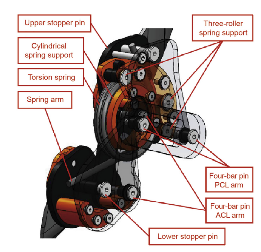
Fig.9.CAD rendering showing the double-layer linkage design.
《Fig. 10》
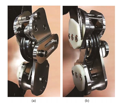
Fig.10.Exoskeleton knee joint with embedded torsion spring.(a)Inner side;(b)outer side.
Because the coil diameter of a torsion spring always decreases under spring deflection, a common support design is a full-circle cylinder with a scale based on the minimum inner coil diameter, although it cannot be fit with an unloaded spring. Installing a torsion spring concurrently with the flexion-angle-dependent knee CoR is a key design challenge. We developed a three-roller spring support design on the outer rim that not only provides a fit assem-bly to the non-deflected spring, but also adapts over the deflection range[13]. The CAD rendering in Fig.11 shows the knee joint at different knee angles.
《Fig. 11》

Fig.11.CAD rendering showing the knee joint at different knee angles. (a)55° flexion; (b)90°flexion; (c)120°flexion.
《4.Cycling experiment》
4.Cycling experiment
《4.1.Experimental environment》
4.1.Experimental environment
We established an indoor cycling environment, shown in Fig.12, to study the influence of cycling power and passive cycling support on quadriceps femoris activity. A testing bicycle was fixed to a magnetic cycling trainer with a climbing block supporting the front wheel. Real-time cycling speed and leg cadence information were provided by a bicycle speedometer. On both of the participants’legs, dry surface EMG electrodes (Logical Product Corp.) were placed over the RF muscles to measure the EMG signal with a 1 kHz sampling frequency.
《Fig. 12》
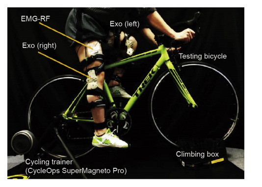
Fig.12.Indoor stationary cycling environment.Exo:exoskeleton.
《4.2.Wheel-accelerating system》
4.2.Wheel-accelerating system
To enable participants to perform constant-power cycling on the trainer at a constant velocity and against constant torque, we developed a wheel-accelerating system to initially spin the rear wheel to the target velocity of 30 km · h-1, which corresponds to 200 and 225 W cycling powers in the road and interval training modes,respectively. A Turnigy G32 brushless outrunner 600kv motor was used in the friction drive mechanism, as shown in Fig.13.A gap is designed between the outrunner circumference and the rear tire when the lever mechanism is in the neutral position. With rapid motor acceleration, the reaction torque drives the lever mechanism in the opposite direction. Thus, the outrunner circumference contacts the surface of the rear tire. With more driving friction, the reaction force at the contact surface pushes the lever mechanism tightly against the tire. After reaching the desired velocity, the lever mechanism automatically disengages from the tire as the motor stops rotating so that the subject can begin cycling to maintain the constant velocity.
《Fig. 13》
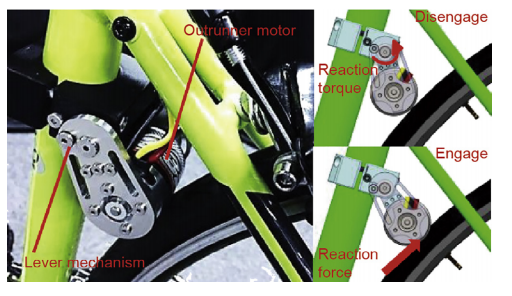
Fig.13.Friction drive mechanism of the wheel-accelerating system.
《4.3.Experimental procedure》
4.3.Experimental procedure
Because the exoskeleton prototype supports the knee-extension moment in cycling at knee angles greater than 55°, the duration of the torsion spring support corresponds to the pedal crank angle from 150° prior to 80° after TDC. As a knee extensor muscle , the RF is active at pedal crank angles from 65° until 115° after TDC[19]. Placing surface EMG electrodes over the RF muscle is also more convenient than placing them over the vasti while the participant is wearing the exoskeleton prototype.
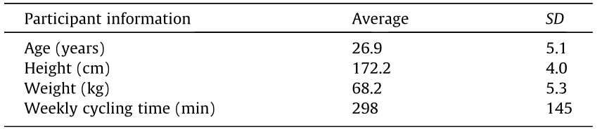
Assuming that quadriceps activity increases with cycling load at the same leg cadence, eight healthy male participants familiar with cycling performed two power cycling tests to show the influence of changing muscle activity on the spectral component of the surface EMG. Participant information is summarized in Table 2. In each experiment,the participant performed a 2 min warm up by 225 W cycling on a trainer, followed by a 10 min rest. After placing the surface EMG electrodes over the RF muscle of both legs,the participants performed three 2 min cycling trials with 10 min breaks between each trial. At 30 km·h-1 and a leg cadence of 57 r·min-1 , the order of the cycling trials was as follows: 225 W cycling with the exoskeleton (Exo225) prototype on both legs, 225 W cycling without the exoskeleton (Leg225), and 200 W cycling without the exoskeleton (Leg200).
《Table 2》
Table 2 Participant information for the cycling experiment(eight participants).
《5.Results and discussion》
5.Results and discussion
《5.1.Root-mean-square EMG》
5.1.Root-mean-square EMG
Recorded at a sampling frequency of 1 kHz, the surface EMG obtained from the cycling experiment consisted of raw EMG data measured in volts and RMS EMG data. Collected from 90 s intervals of constant-power cycling, the RMS EMG data corresponding to the right and left leg RF muscles of Participant 3 are plotted against the cycling time in Figs. 14(a)and 15(a), respectively.From all the cycling trials with and without the exoskeleton, the RMS EMG shows uniform repetitive muscle activity throughout the 90 s of cycling.
According to the 20 s enlarged plots of both legs in Figs.14(b) and15(b), the decrease in RMS EMG with cycling power can be observed by comparing the results of the cycling trials without the exoskeleton (Leg225 and Leg200). When cycling at 225 W with the exoskeleton (Exo225), the RMS EMG of the RF muscle can be reduced on both legs, in comparison with the cycling trial without exoskeleton at the same cycling power (Leg225). The result of the left RF muscle shows most clearly that the RMS EMG can be reduced to nearly the same level as during 200 W cycling without exoskeleton (Leg200)
《Fig. 14》

Fig.14. (a)RMS EMG recorded from the right leg RF muscle of Participant 3 during 90 s intervals; (b)enlarged plot during 20 s intervals.
《Fig. 15》

Fig.15.(a)RMS EMG recorded from the left leg RF muscle of Participant 3 during 90 s intervals; (b)enlarged plot during 20 s intervals.
《5.2.EMG time–frequency analysis》
5.2.EMG time–frequency analysis
Since the influence of variation in muscle activity on the spectral component of the surface EMG is still ambiguous, the raw EMG data of each individual RF muscle obtained from the cycling tests were analyzed in time–frequency via a CWT. Combining the wavelet coefficient of both leg RF muscles, the time–frequency plot of Exo 225 performed by Participant 3 is shown as an example in Fig.16(a). The instantaneous EMG-MDF, along with the linear regression line, is plotted against cycling time. In agreement with the results of Ref.[22], there is no significant sign of localized muscle fatigue in our test, since the decrement of the EMG-MDF over the 90 s cycling interval was less than 5% of its initial value. Using the same data result, the time–frequency plot is enlarged to 10 s intervals in Fig.16(b). The high-density wavelet coefficient obtained from the RF muscles of both legs can be observed roughly twice per second, corresponding to the 57 r · min-1 cycling leg cadence.
《Fig. 16》
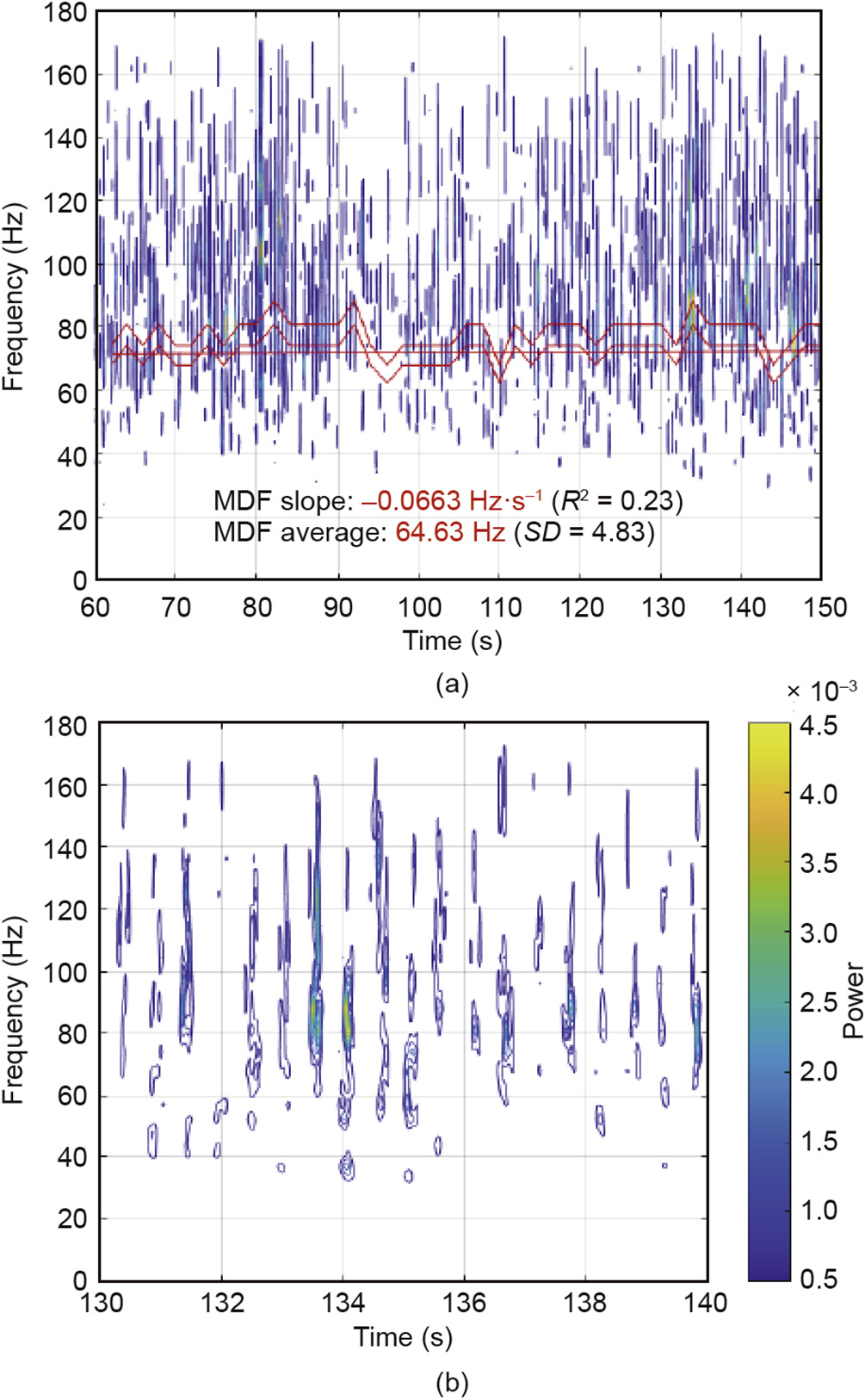
Fig. 16. (a) EMG time–frequency plot of both RF muscles of Participant 3 obtained from Exo225; (b) enlarged plot during 10 s intervals.
The average EMG-MDF values from all eight participants during all cycling conditions–that is, Exo 225,Leg 225, and Leg 200–are compared in Fig.17. When comparing the results of the cycling trials without the exoskeleton (Leg225 and Leg200) in each participant, a lower EMG-MDF can be observed from the cycling trial at 200 W (Leg200). When comparing the cycling trials at 225 W (Exo225 and Leg225), lower EMG-MDFs can be seen from the cycling with the exoskeleton (Exo225) in all eight participants.
《Fig. 17》
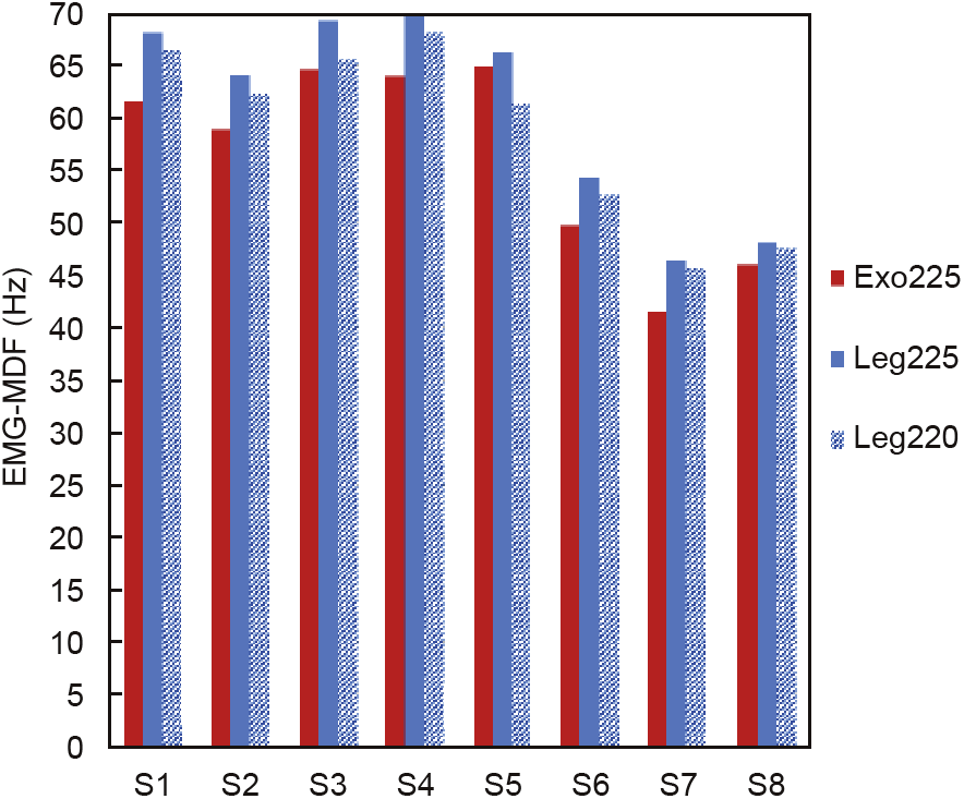
Fig.17.Average values of the EMG-MDF from both RF muscles over 90 s of cycling by eight participants(S1–S8).
《6.Conclusion and future work》
6.Conclusion and future work
Taking advantage of the unbalanced effort required from the knee extensor and flexor muscles during cycling, we have proposed a passive cycling support concept that stores energy from knee flexion and releases it to support knee extension. We carried out experimental validation using constant-power cycling with the developed exoskeleton worn on both legs of eight healthy male participants.Surface EMG of the knee extensor RF muscle was recorded to determine the reduction in quadriceps femoris activity. The average EMG-MDF over the cycling time increased with exercise intensity. This observation can be used as an alternative method to compare the level of muscle activity in other dynamic exercise activities. At the same cycling power, RF muscle activity decreased with passive cycling support,according to the decreasing average EMG-MDF. The ability to modify the unbalanced effort required from the quadriceps and hamstring during cycling without external energy sources can be applied to cycling enhancement and rehabilitation applications.
Developed from this fully passive wearable-support concept,our exoskeleton prototype consumes no electrical energy and delivers no netpositive mechanical work.Because of human–device interfacing losses, the overall mechanical work done by muscles might be increased in practice. The reduction in quadriceps muscle activity is only one advantage proven by this preliminary validation. For a better understanding of human physiology, the influence of passive cycling support on the activity of other muscle groups must be studied. Because of the fas-tening strap locations, the study of the hamstring muscle activity is limited in this study. Considering the effect on oxygen consumption or metabolic energy is also important for future studies.
《Compliance with ethics guidelines》
Compliance with ethics guidelines
Ronnapee Chaichaowarat, Jun Kinugawa, and Kazuhiro Kosuge declare that they have no conflict of interest or financial conflicts to disclose.


 京公网安备 11010502051620号


