
《1. Introduction》
1. Introduction
In the 21st century, humanity faces increasing concerns about climate change, which brings about extreme conditions such as high winds, flooding, and unusual heat waves. Infrastructure designers must consider adapting infrastructure to extreme loading so as to maintain community resilience. At the same time, the mitigation of climate change caused by the rise of the earth’s average surface temperature is becoming increasingly urgent. Reducing the release of greenhouse gases associated with civil infrastructure construction and use must be a high priority of infrastructure designers. Because of the large size and long lifecycle of infrastructure, enhancing the ‘‘greenness” of construction materials—and especially their durability—can contribute significantly to the mitigation of climate change. Adaptation of civil infrastructure to climate change and the mitigation of climate change are grand challenges for current and future civil engineers.
The middle panel of Fig. 1 shows the characteristics of civil infrastructure that are necessary to support human habitation for current and future generations. Durability extends the service life of a structure without repeated repairs or the associated economic and environmental costs. It also requires that structures not be weakened by degradation in a way that limits their resilience. A structure cannot be sustainable without being both durable and resilient. Lack of resilience implies repeated reconstructions, particularly in the face of climate-change-induced hazards. According to the World Commission on Environment and Development [1], “sustainable development is development that meets the needs of the present without compromising the ability of future generations to meet their own needs.” Sustainable infrastructure engineering can be defined as an integrated system of material development, structural design and construction, and infrastructure management that is consistent with the principles of sustainable development.
《Fig. 1》

Fig. 1. Integrating high-performance characteristics with multi-smart functions in a concrete material in order to enhance infrastructure durability, resilience, and sustainability.
The desirable characteristics of concrete infrastructure imply several high-performance requirements for modern concrete material. First and foremost, this material must be green, with low embodied energy and low carbon intensity. This is necessary in order to directly support infrastructure sustainability. Second, high-performance concrete must be ductile in order to prevent catastrophic failure induced by brittle fracture of the material. This is critical in order to directly support infrastructure resilience. Ductility also contributes to infrastructure durability, such as by the suppression of concrete cover spalling, a common phenomenon in concrete structure deterioration. But the most direct means of enhancing infrastructure durability should be the ability of the high-performance concrete to autogenously control its crack width, in order to limit the ingress of water and aggressive agents through the cover, and thus eliminate many common infrastructure deterioration mechanisms such as the corrosion of reinforcing steel. Thus, a truly high-performance concrete must simultaneously possess the characteristics of material greenness, tensile ductility, and autogenous crack-width control, as indicated in the left panel of Fig. 1.
A smart material is defined as a material that has the ability to respond to stimulus of an external environment, and that provides a useful function without human intervention. For example, selfhealing material responds to water and air and conducts damage repair in order to restore its intrinsic mechanical and transport properties. It therefore supports both infrastructure durability and resilience. Self-sensing material responds to external loading, and identifies the location and extent of damage it suffers. It supports infrastructure durability by informing decision-makers when and where repair is needed, and supports infrastructure resilience by providing information on whether a structure may be put back in service, thus allowing an earlier return to use of the structure after a major load event. If self-sensing and self-healing were combined, the material would be able to communicate the level of healing recovery without external intervention. The self-thermal auto-adaptive function allows the material to alter its heat storage capacity by responding to a rise in air temperature, thus limiting the temperature increase in the interior of a building and minimizing the need for energy-intensive air conditioning. This function directly addresses the sustainability of a building in the use phase of its life-cycle. Photocatalytic material responds to ultraviolet (UV) irradiation from sunlight by creating electron-hole pair and generating highly active hydroxyl radicals that minimize the need for water- and energy-intensive washing, and enhances the surrounding air quality of urban structures via pollutant removal. This function also directly addresses infrastructure sustainability. These examples of smart material functions, as shown in the right panel of Fig. 1, add significant value to high-performance concrete, through their contributions to infrastructure durability, resilience, and sustainability.
To advance civil infrastructure durability, resilience, and sustainability in the 21st century, it is highly desirable to develop high-performance concrete with multi-smart functions. Although a significant amount of research has gone into high-performance characteristics and smart functions, much more work is needed to fully develop an industrially scalable concrete material that embodies these desirable characteristics and smart functions. It may be extremely challenging to develop concrete that simultaneously possesses both high performance and smartness, but this should be our goal, for the sake of our planet—Mother Earth and her inhabitants.
Engineered cementitious composite (ECC) is a concrete material that attempts to embody the above aspirations. This material has been undergoing extensive research and development by an increasingly global community of researchers and industrial early adopters. Some highlights of the characteristics and functionalities of ECC are described below. Examples of applications of ECC in transportation, building, and water infrastructures can be found in Ref. [2]. This material is also known as strain-hardening cementitious composite (SHCC)—a name that emphasizes the unique tensile stress–strain behavior of this material.
《2. Contribution of ECC to infrastructure durability》
2. Contribution of ECC to infrastructure durability
The durability of civil infrastructure is influenced by the structural design and by the use and exposure environments. However, the durability of concrete material in the structure also plays a critical role. The durability of concrete in a structure is different from that of concrete in the laboratory, in that the material is expected to be under load in the field. The loading may be due to dead or live loads. It may also be induced loading due to imposed deformation such as thermal cycles or foundation settlements, and the restraint of the concrete members. Whatever the cause, loading may lead to cracking of the concrete material. Although the textbooks teach that concrete structures are designed to crack, the reality is that cracks accelerate structural deterioration and shortens service life.
Fig. 2 plots various forms of deterioration, including the increase in transport phenomena such as water permeation, chloride ion diffusion, and corrosion of reinforcing steels, as a function of crack width. These plots are normalized by the corresponding degradation level at a crack width of 0.1 mm, based on data collected from published literature [3–9]. What is striking in these plots is the common elbow shape of the degradation curves. Below a 0.1 mm crack width, and especially below 0.05 mm, the degradation level is minimal. Above a 0.1 mm crack width, however, the degradation level accelerates nonlinearly. These plots suggest that crack width plays a critical role in the service life of civil infrastructures.
《Fig. 2》

Fig. 2. Deterioration rates as measured by (a) permeability coefficient, (b) effective chloride diffusion coefficient, (c) corroded steel diameter reduction (30 and 40 mm cover thickness), and (d) cumulative mass loss show acceleration when the crack width exceeds 0.1 mm (14 and 24 months accelerated corrosion tests). The deterioration rate data have been normalized by that for a 0.1 mm crack width of one data set for each graph. HPC-SF: high-performance concrete with silica fume; HPC: high-performance concrete; OPC: ordinary Portland cement.
In laboratory durability tests, concrete specimens are subjected to various exposure environments. These are important tests to understand the influence of environmental exposures on material integrity, governed by material chemistry and microstructure. The data in Fig. 2 suggest, however, that true structural durability requires the control of crack width in the field, beyond having the proper material chemistry and microstructure.
In the past, crack control in structures was intended to be taken care of by steel reinforcement. Experience reveals that this has not been a reliable approach. A more reliable approach would be to build autogenous crack-width control directly into the material itself. That is, the crack width would be designed to be an intrinsic property of the concrete, regardless of loading, reinforcement details, structural dimensions, or the exposure environment.
Fig. 3 shows a tensile stress–strain curve of an ECC [10]. Beyond the elastic limit, the ECC exhibits a strain-hardening response. That is, the load-carrying capacity continues to rise as damage is developed in the uniaxially tensioned specimen. An increasing number of microcracks form, but their width remains limited to less than 0.06 mm. This specimen does not contain any steel reinforcement.
《Fig. 3》

Fig. 3. Tensile stress–strain relation of a typical ECC showing a high ductility of 3.8% and autogenously controlled crack width below 0.06 mm. Adapted from Ref. [10] with permission of American Concrete Institute, ![]() 2007.
2007.
Fig. 4 [11] shows the development of crack width in normal concrete and ECC specimens of various sizes. The cracks were generated by restrained shrinkage under drying. For normal concrete, the crack width increases linearly with specimen dimension, and increases indefinitely. For ECC, the crack width is limited to below 0.05 mm and is independent of specimen dimension.
《Fig. 4》

Fig. 4. Unlike concrete, crack width (w) in ECC is independent of specimen length (L) and is an intrinsic material property [11].  is the drying shrinkage strain and
  is the creep strain.
These two experiments confirm that crack width in ECC is essentially independent of loading and specimen size. Crack width in ECC is also independent of steel reinforcement.
The durability performance of ECC has been extensively documented [4,5,12–14]. To illustrate this durability, Fig. 5 [5] shows the effective chloride ion diffusivity of specimens taken from beams subjected to different levels of bending deflection. Although an increase in effective chloride ion diffusivity is observed in the ECC, this increase is linear, which reflects the rising number of cracks in the beam at higher imposed deformation. In contrast, the mortar shows an effective chloride ion diffusivity that increases exponentially, as a result of the increasing crack width of a single crack. This experimental data suggest that crack width is more critical to structural durability than crack number. The intrinsically tight crack width in ECC slows the ingress of chloride ion into the concrete cover of a structural element. The correlation between crack width and chloride ion diffusion coefficient is consistent with the elbow shape degradation curve shown in Fig. 2(b).
《Fig. 5》

Fig. 5. Effective chloride ion diffusion coefficient of cracked mortar and ECC. While the mortar specimen shows an exponential increase in diffusion coefficient with beam preload deformation, the ECC beam shows a linear increase. RH: relative humidity. Adapted from Ref. [5] with permission of American Concrete Institute, ![]() 2007.
2007.
The importance of crack width to structural durability is highlighted by experimental evidence of the corrosion rate of steel reinforcements in beams subjected to an accelerated corrosion exposure regime. A pair of beams was preloaded and kept in flexure in the configuration shown in Fig. 6 [12]. The accelerated corrosion regime involved 28-day exposures to wet (saltwater shower 90% relative humidity (RH), 2 days) and dry (60% RH, 5 days) cycles. The control reinforced concrete (R/C) beam had a single crack, whereas the reinforced ECC (R/ECC) beam had multiple cracks with a crack width below 0.01 mm. The corrosion rates of the R/C and R/ECC beams showed distinctively different deterioration modes and magnitude. In the R/C beam, the steel reinforcement revealed severe corrosion where the concrete cracks, while the rest of the steel reinforcement remained in an uncorroded condition (Fig. 7(a)) [13]. In the R/ECC beam, the steel reinforcement revealed corrosion along multiple points associated with the multiple cracks in the ECC, but the corrosion rate was substantially lower (Fig. 7(b)). This contrast in the corrosion deterioration rate and damage pattern is a direct reflection of the crack control behavior of ECC. The autogenously controlled tight crack width in the ECC limits the chloride ion penetration through the ECC cover and the subsequent corrosion of the rebar. This test result is consistent with the elbow-shaped degradation curve shown in Figs. 2(c) and (d).
《Fig. 6》

Fig. 6. After crack induction by tightening the nuts, the preloaded beam assembly was exposed to a 28-day accelerated corrosion environment [12].
《Fig. 7》

Fig. 7. Corrosion rates along the steel reinforcement for (a) an R/C beam and (b) an R/ ECC beam. In the latter case, corrosion was found to be spread out along the rebar but at a substantially lower rate than that found for the reinforcement in the R/C beam. Adapted from Ref. [13] with permission of American Concrete Institute,![]() 2008.
2008.
Although the above discussions used an average crack width to describe the level of damage and its effect on a variety of deterioration mechanisms, it should be noted that the crack-width distribution in ECC typically shows a log-normal form, and that the large cracks may dominate the transport and deterioration mechanism [6,15,16]. A comprehensive review of the durability of ECC materials can be found in Ref. [15].
《3. Contribution of ECC to infrastructure sustainability》
3. Contribution of ECC to infrastructure sustainability
The enhanced durability of R/ECC structures implies reduced repair events during the use phase of a structure. In turn, the energy consumption and pollutant emissions associated with repair or replacement events can be substantially curtailed. This contribution to infrastructure sustainability by ECC was quantified for a bridge deck located in Southern Michigan. The bridge deck was retrofitted with an ECC link-slab developed for conventional joint replacement (Fig. 8 [17]). The link-slab implementation was carried out in 2005, motivated by the frequent maintenance needs that are typical of expansion joints on bridge decks.
《Fig. 8》
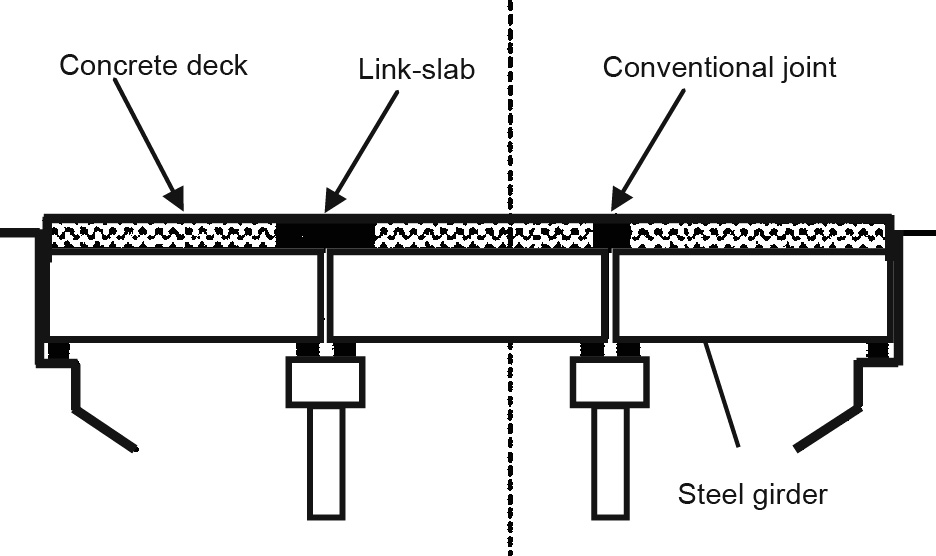
Fig. 8. Bridge deck with ECC link-slab replacing a conventional expansion joint. Adapted from Ref. [17] with permission of Springer, ![]() 2009.
2009.
A life-cycle assessment model [18] was developed to compute the sustainability metrics, considering the durability characteristics of R/ECC, as highlighted above. The difference in repair schedules for the deck with a conventional expansion joint and the one with an ECC link-slab is illustrated in Fig. 9 [18]. The model accounts for changes in traffic patterns due to repair events.
《Fig. 9》

Fig. 9. Repair frequency for conventional versus ECC link-slab systems. Adapted from Ref. [18] with permission of American Society of Civil Engineers, ![]() 2005.
2005.
Fig. 10 [18] shows a comparison between the total primary energy and carbon dioxide (CO2) equivalent for the ECC retrofitted deck and those for the deck with a conventional expansion joint. Savings of 40% in total primary energy and 33% in CO2 equivalent were found for the more durable bridge deck with the ECC linkslab retrofit. A significant amount of savings was derived from the reduction in traffic pattern alteration due to the reduced number of repair events (Dtraffic) during the service life of the deck (60 years). Savings were also achieved by the reduced volume of material needed for repair or joint replacement. This study highlights the value of the tensile ductility and tight crack width of ECC for enhanced infrastructure durability and sustainability. While material greenness is important in reducing the embodied energy and carbon of construction material, structural durability plays an even more important role in attaining infrastructure sustainability.
《Fig. 10》
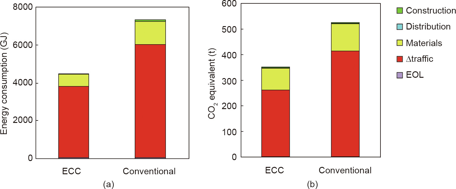
Fig. 10. Results from the life-cycle assessment model, showing life-cycle (a) primary energy consumption and (b) CO2 equivalent for the ECC and conventional bridge deck systems. Energy and carbon footprint savings of 40% and 33% were achieved by replacing the conventional expansion joint with an ECC link-slab. The contributions of distribution and end of life (EOL) are too small to be visible on the scale used. Adapted from Ref. [18] with permission of American Society of Civil Engineers, ![]() 2005.
2005.
Greening of ECC has received much attention. The cementitious binder can be partially or fully replaced by supplementary cementitious materials (e.g., high-volume fly ash [19] or granulated blastfurnace slags [20]), by filler such as iron ore tailing powder [21], or by Portland-cement-free binder such as fly ash geopolymer [22]. The manufactured silica sand that is typically used in ECC can be substituted by limestone powder [20] or by industrial wastestream materials such as foundry calcinator baghouse sand [23], foundry green sand [23], or iron ore tailings [24]. The polyvinyl alcohol (PVA) fiber commonly used in ECC can be substituted by lower energy-intensive polypropylene fiber or using renewable plant fiber such as curaua [25]. Lepech et al. [23] have suggested a systematic approach to the greening of ECC, in order to ensure fresh property suitable for casting and retain the unique tensile ductility of ECC.
《4. Contribution of ECC to infrastructure resilience》
4. Contribution of ECC to infrastructure resilience
A resilient structure can be described as one that delays failure for a given load event, limits the degradation of function due to failure, and recovers at less time and lower cost. This concept is illustrated in Fig. 11, which compares the quality of a conventional structure with that of a more resilient one.
《Fig. 11》

Fig. 11. Resilient infrastructure is defined by delayed failure, limited degradation during the event, and rapid post-event recovery. The dashed line illustrates the quality of a more resilient structure that delays failure (from t0 to ![]() ), limits degradation of function (from Q to Q'), and recovers function faster (shortens from (t1 -t0) to
), limits degradation of function (from Q to Q'), and recovers function faster (shortens from (t1 -t0) to  ) after a major load event, when compared with a less resilient structure.
The tensile ductility of ECC offers R/ECC structures significant advantages in terms of structural resilience. This is illustrated by the contrast in the hysteretic behavior of an R/ECC beam versus that of an R/C beam under reversed cyclic loading (Fig. 12) [26]. The contrast in damage between the two beams is illustrated in Fig. 13 [26]. Even without shear stirrups, the R/ECC beam was able to limit the damage via the ductility of ECC in tension and shear [26].
《Fig. 12》
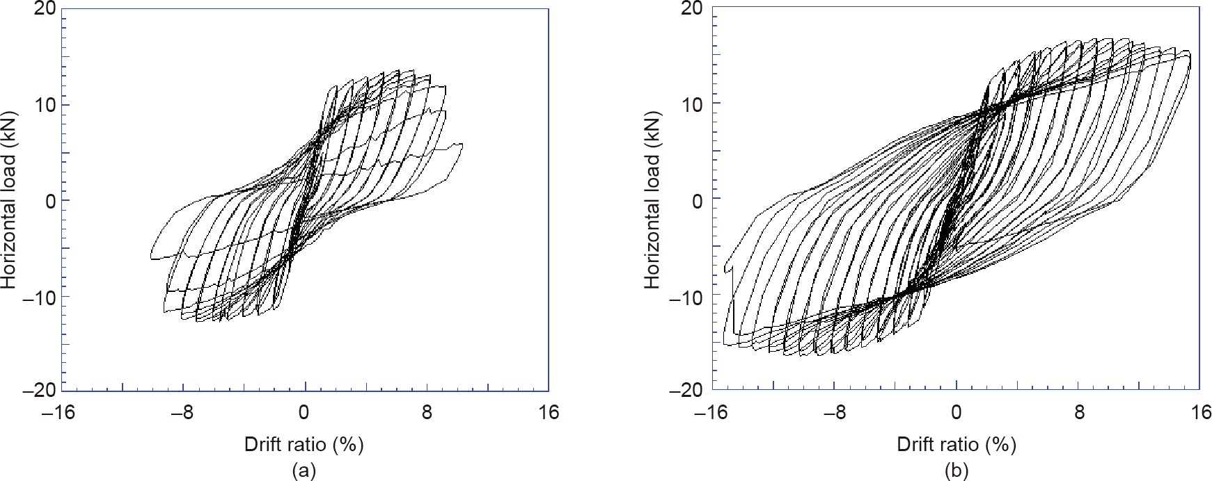
Fig. 12. Hysteresis behavior of (a) R/C and (b) R/ECC flexural members. Failure is delayed to a higher load and deformation. The rate of load drop after peak is substantially lower in the R/ECC member due to continued confinement effectiveness of ECC. Adapted from Ref. [26] with permission of American Concrete Institute, ![]() 2002.
2002.
《Fig. 13》

Fig. 13. Deflected shape and damage pattern at 10% drift for (a) R/C and (b) R/ECC flexural members. Bond splitting was followed by spalling of cover in the R/C member. In the R/ECC member, spreading of damage away from the base is evident. The contrast in the damage patterns suggests that R/ECC members can recover faster after a seismic event, in some cases requiring minimal repair. Adapted from Ref. [26] with permission of American Concrete Institute,![]() 2002.
2002.
Numerous experimental studies on beams, columns, frames, and walls have arrived at the same conclusion: The tensile ductility of ECC contributes to structural resilience [27–32]. This advantage has been exploited in several new buildings in which R/ECC coupling beams were used to enhance seismic safety, construction ease, and usable floor space, with savings in building cost [33]. Recently, over a thousand R/ECC precast dampers were deployed to retrofit a viaduct along the eastern shoreline of Japan.
《5. Multifunctional ECC》
5. Multifunctional ECC
《5.1. Self-thermal auto-adaptive ECC》
5.1. Self-thermal auto-adaptive ECC
Following the pioneering work of Alkan [34], self-thermal autoadaptive ECC has been developed [35] to support energy conservation in buildings. Phase change materials (PCMs) can temporarily store energy by absorbing heat by switching from a solid to a liquid phase, and can then release heat by switching back from a liquid phase to a solid phase. Paraffin wax, which undergoes such a phase change at 22.8°C, is a suitable PCM for such applications, as the transition temperature coincides with changes in human comfort level. Fig. 14 [35] shows 5μm micro-encapsulated PCM embedded inside ECC. The resulting PCM-ECC reveals a distinct rise in thermal capacitance at the expected transition temperature (Fig. 15 [35]). Compared with the ECC without PCM, the PCM-ECC with 3% PCM has a thermal capacitance about 35% greater. The thermal capacitance curve is reversible when the temperature returns below the transition temperature, so this functionality is repeatable indefinitely.
《Fig. 14》
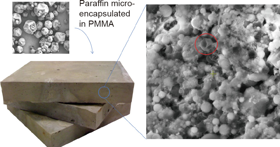
Fig. 14. Self-thermal auto-adaptive ECC containing microcapsules of paraffin-wax-based PCM. The 5 μm PCM microcapsules (in red circle) appear as crumbled spheres or frozen dried peas. (The smooth spherical particles shown on the micrograph of a fractured surface are unreacted fly ash particles.) The paraffin wax undergoes a phase change from solid to liquid as the temperature rises above 22.8°C. The presence of these micron-size particles with low bonding properties to cement alters the microstructure and properties of the ECC. PMMA: poly(methyl methacrylate). Adapted from Ref. [35] with permission of Elsevier Ltd., ![]() 2014.
2014.
《Fig. 15》

Fig. 15. A plot of the increase in the thermal capacitance of 3% PCM-ECC and ECC with temperature. The thermal capacitance shows a jump of 35% at about 23°C, which corresponds to the temperature at which the phase change of the paraffin wax from solid to liquid occurs. This latent heat absorption results in temporary energy storage and a higher apparent thermal mass that can be used for energy efficiency enhancement in buildings, for example. The phase change phenomenon is reversible when the temperature drops and the liquid wax returns to a solid state. Adapted from Ref. [35] with permission of Elsevier Ltd., ![]() 2014.
2014.
In a study using PCM-ECC for a solar chimney in a home in Ann Arbor, MI, the peak temperature in the interior of this building was found to be maintained at below 23°C without air conditioning, and with a peak temperature decreased by 5°C and delayed by 2 h compared with an equivalent situation using conventional concrete with no phase change functionality.
The inclusion of 3% PCM microcapsules is synergistic with the tensile properties of ECC, which has a tensile strain capacity reaching 4% and a crack width of 10 μm. However, the compressive strength is negatively affected, and drops to about 28 MPa.
《5.2. Self-healing ECC》
5.2. Self-healing ECC
A comprehensive review of the self-healing phenomena of cement-based materials can be found in Ref. [37].
ECC possesses the unique self-healing capability of its microcrack damage. Self-healing in ECC combines both the sealing function and the binding function of the crack faces. The self-sealing function restores transport properties such as water permeation and chloride diffusion, whereas the binding function restores mechanical properties such as tensile strength, stiffness, and ductility. It was found [36] that the self-healing functions of ECC are most effective when the crack width is below 50 lm, and when the damaged material is exposed to cycles of wetting and drying. Fig. 16 [36] shows the resonant frequency (RF) ratio as a function of crack width. A drop in RF ratio is observed after microcrack introduction. Full recovery of the RF ratio (to 100%) is evident after exposure to wet–dry cycles. Apart from RF recovery, evidence of healing has also been investigated using three-dimensional (3D) X-ray computed micro-tomography [38] and scanning electron microscopy/energy dispersive X-ray spectroscopy (SEM/EDS) [39], confirming that a tighter crack width heals better.
《Fig. 16》

Fig. 16. RF decreases with increasing crack width. Recovery of RF due to selfhealing after wet–dry cycles is enhanced by tighter crack width. In this study, recovery of RF is 100% when crack width falls below 50 lm. Adapted from Ref. [36] with permission of Elsevier Ltd., ![]() 2009.
2009.
The mechanism of self-healing is a combination of continued hydration and pozzolanic reactions when unhydrated cement grains and pozzolans come into contact with water. The resulting calcium silicate hydrates (CSHs) fill the microcrack and bind the crack faces. In addition to CSH, scanning electron microscopy (SEM) confirmed the formation of calcium carbonate (CaCO3) crystals inside the crack (Fig. 17), likely a result of reactions between the calcium hydroxide (CaOH) phase and carbonic acid from water-dissolved CO2 in the surrounding air [39]. These rehealing products were found to form on both the crack walls as well as on the surfaces of the bridging fibers.
《Fig. 17》

Fig. 17. SEM and EDS detect (a) the presence of CSH and (b) the presence of CaCO3 crystals in healed cracks in ECC. Both healing products were observed in the same ECC specimen sample. Adapted from Ref. [39] with permission of American Concrete Institute, ![]() 2010.
2010.
The self-healing function of ECC is likely to last, since the shelflife of unhydrated cement grains is known to be long. Yıldırım et al. [40] demonstrated experimentally that self-healing remained effective with one-year-aged ECC specimens after exposure to water, especially water rich in CO2 (Fig. 18).
《Fig. 18》

Fig. 18. One-year-aged ECC specimen (a) damaged by splitting tension loading shows self-healing after (b) 15 days and (c) 30 days of exposure to CO2-rich water. Adapted from Ref. [40] with permission of Elsevier Ltd., ![]() 2018.
2018.
The self-healing function of ECC was found to be repeatable [36,41]. Specimens damaged by preloading were found to recover stiffness and strength after exposure to 10 wet–dry cycles (Fig. 19).
《Fig. 19》

Fig. 19. Self-healing of ECC subjected to repeated loading. (a) Specimen in air shows low stiffness upon reloading; (b) specimen exposed to 10 wet–dry cycles shows stiffness recovery upon reloading; (c) specimen subjected to two repeat loadings still shows stiffness recovery when healing is allowed with wet–dry cycles. Adapted from Ref. [41] with permission of Japan Concrete Institute, ![]() 2010.
2010.
《5.3. Self-cleaning and air-purifying ECC》
5.3. Self-cleaning and air-purifying ECC
ECC can also be made to have self-cleaning and air-purifying functionalities, following the seminal work of Cassar et al. [42,43].
By including 10% TiO2 nanoparticles in ECC, the reflectance loss that occurred when the ECC was dyed by rhodamine B (RhB) was shown to be recoverable when the dyed ECC was exposed to UV irradiation [44] (Fig. 20). Similarly, the concentration of NO and NOx in a reaction chamber was shown to dramatically decrease with exposure of TiO2-ECC to UV irradiation (Fig. 21).
《Fig. 20》
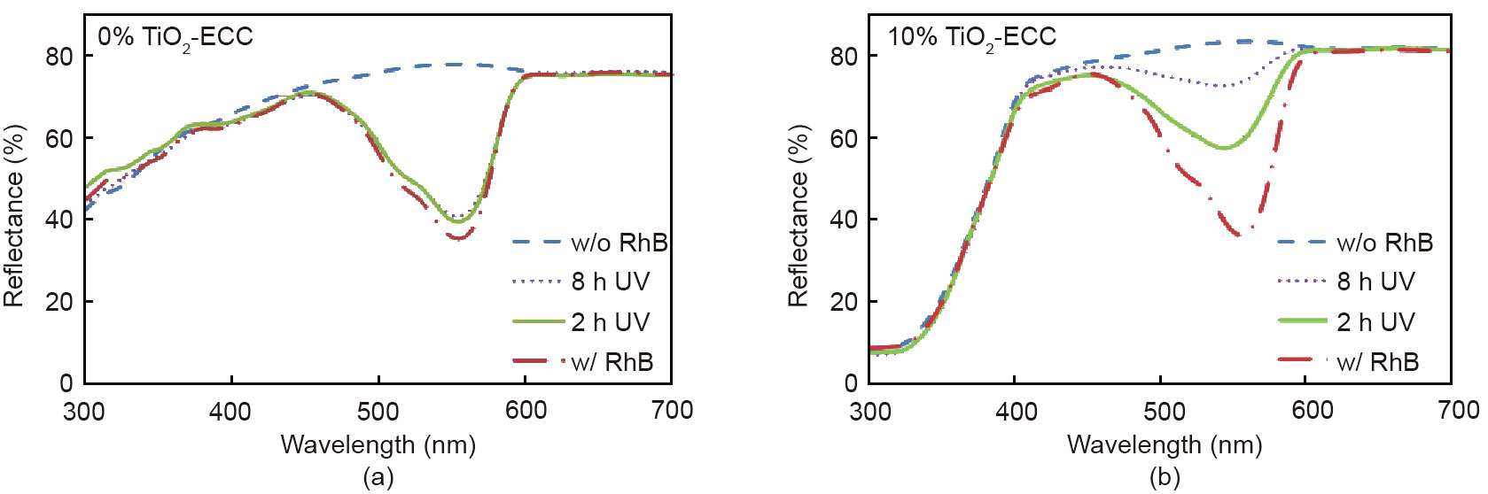
Fig. 20. Dyeing ECC with RhB lowers the reflectance in the wavelength range of 450–600 nm. (a) Negligible recovery of reflectance on exposure to UV irradiation was found in ECC without TiO2; (b) significant recovery was found in TiO2-ECC. w/o: without; w/: with. Adapted from Ref. [44] with permission of Elsevier Ltd., ![]() 2015.
2015.
《Fig. 21》

Fig. 21. Air-purifying function of ECC functionalized with TiO2. (a) Without UV irradiation, a slow decrease in the concentrations of NO and NOx was observed in the reaction chamber. (b) With UV irradiation, a rapid drop in the concentration of these gases was observed over a 10 min time period, demonstrating the photocatalytic air-purifying function. 1 ppm = 10-6 .
《5.4. Self-sensing ECC》
5.4. Self-sensing ECC
Self-sensing concrete material was pioneered by Chung [45], among others. Self-sensing ECC was developed to automatically detect and report damage [46]. This functionality is built on the principle that ECC is a semi-conducting material with electrical resistivity that is sensitive to changes in the material microstructure due to loading. To be specific, microcracks induced by loading alter the electrical conducting pathways. Because cracks are by definition anisotropic, the pathways that are most affected are those that pass perpendicular to the crack lines. This concept allows the use of electrical impedance tomography (EIT) to map crack damage in ECC. EIT is based on stimulating a specimen with regulated sinusoidal alternating current (AC) and determining the amplitude and phase of the voltage, from which impedance can be computed as a function of AC frequency. When an array of electrodes for voltage monitoring on the perimeter of the specimen is utilized, the data collected can be inverted for electrical conductivity for each point in the medium. Fig. 22 [46] shows this principle in action. The detected microcrack damage at different stages of loading based on electric conductivity maps corresponds well to the visual images of the microcracks, although the resolution could be further improved.
《Fig. 22》

Fig. 22. (a) A tensile stress–strain curve indicating the strain levels (B–E) at which (b) conductivity maps were made using EIT. The corresponding surface cracks are also shown (pen marked for clarity). Larger cracks are successfully imaged, but smaller cracks require improvement in resolution [46].
The self-sensing functionality of ECC can be utilized to selfreport the structural condition after a major loading event. This information may feasibly support decision-making regarding continuing operation, repairing structures, or replacing structures, with improved efficiency and with less danger to first responders in a major load event.
《6. Conclusions》
6. Conclusions
This paper describes the need to integrate the highperformance characteristics of concrete material with smart functionalities in order to maximize the durability, resilience, and sustainability of civil infrastructure. Tensile ductility and autogenously controlled tight crack width lend themselves to attaining these desired infrastructure performances. Using ECC as an illustration, this paper shows that functionalities such as selfhealing, self-sensing, self-thermal auto-adapting, self-cleaning, and air purifying can be built into high-performance concrete, thus achieving a modern construction material with high performance and multifunctionalities. Further improvement and material refinements can be made to enhance the wider adoption of these materials in practice. It is hoped that the current state of technology points to a viable direction for the creation of civil infrastructures that support the ambitions of truly smart cities of the future.
While major advances have been made over the last decade in high-performance multifunctional concrete, additional research is needed in order to dramatically green such materials, ideally driving them to become carbon negative. The utilization of CO2 as a resource for this purpose should be given serious consideration. Such a process would combine the engineering of material composition with that of the curing process. There are also opportunities to integrate materials development with construction methods, including modern methods such as architectural-scale 3D printing. Industrial implementation of materials with extreme durability, such as those with autogenous tight crack-width control, will benefit from data from pilot projects in the field. Although compressive strength remains a useful gold standard for the quality of concrete, as has been the case in most structural design codes, there is also a need to update codes to reflect high-performance concrete characteristics that are desirable for the modern demands of infrastructure durability, resilience, and sustainability. Such changes may include minimum tensile ductility and maximum autogenously controlled crack width, for example. Finally, highperformance concrete with multifunctionalities mimicking certain biological materials is fast becoming a reality, and should be exploited to support climate change adaptation and mitigation. This should be a high priority in the civil engineering community and in decision-making bodies for the 21st century.
《Acknowledgements》
Acknowledgements
Much of the experimental data cited in this paper have been obtained by current and former graduate students and post-docs. The data in Fig. 2 were compiled by Dr. Yi Bao and Dr. Duo Zhang. Their contributions are acknowledged. The data in Fig. 21 were generated from an experimental study by Ms. Mingfeng Xu, a scholar at the University of Michigan visiting from Tongji University in China. This work is partially supported by a grant from the CMMI program at the United States National Science Foundation (1634694), by a Visiting Fellowship from the Institute of Advanced Studies at the Hong Kong University of Science and Technology, and by the James R. Rice Professorship and the E. Benjamin Wylie Professorship at the University of Michigan in Ann Arbor.


 京公网安备 11010502051620号


