

《1. Introduction》
1. Introduction
The use of unmanned aerial vehicles (UAVs) for industrial applications is on the rise. UAVs are suitable for a wide range of applications that take place in inaccessible locations and are typically dangerous to human operators, such as power-line inspection [1,2], wind-turbine maintenance [3], the inspection of various structures in facilities [4], and photogrammetry [5]. However, these applications merely involve perceptive tasks. In recent years, it has been demonstrated that aerial robots can effectively perform manipulation tasks as well [6].
Aerial manipulation remains a challenging task, as it has extra requirements; the platform is usually delicate and remains in an unstable equilibrium in the air. In order to perform manipulation tasks, it is necessary to provide the robot with various capabilities such as perception, planning, and, in general, smart capabilities. It is also necessary to equip the robot with the appropriate hardware to perform the desired tasks. The purpose of introducing robots in these applications is to provide a more efficient solution to problems, reduce costs (both time and money), and reduce decreases in quality due to faults by human operators resulting from the monotony of some of these tasks. Instead, the operator is given a more important role that cannot be performed by robots.
Manipulation involves interaction with physical objects using manipulators, and may include grasping objects, moving them, or maintaining contact with a stiff object. In order to perform such tasks, the robot needs to be able to detect and locate objects, as well as analyze how to interact with the objects. In addition, in order to perform such tasks, it is necessary to plan the actions and movements of the manipulators and prevent them from colliding with the environment and the platform itself.
To perform any manipulation task, it is first necessary to find and track the object to be manipulated. Many computer vision algorithms can be used for this task; these can be classified depending on the application, computational resources, and sensors used.
Region proposal algorithms for the monocular detection of objects are commonly used. These algorithms can be based on simple color algorithms [7,8], features detection [9,10], or machine learning. Novel algorithms use artificial neural networks (ANNs) to detect pre-trained objects. ANNs have been exploited thanks to the field of deep learning and the availability of powerful graphics processing units (GPUs) that boost and parallelize ANNs. The latest designs (SSD [11], RCNN [12], F-RCNN [13], Mask-RCNN [14], and YOLO [15]) have overtaken most traditional objectdetection algorithms. However, detecting instances of objects in color images is insufficient to perform manipulation tasks. It is also necessary to analyze the three-dimensional (3D) information of the object. With this purpose, recent research on deep neural networks (DNNs) has extended ANNs to compute the six-dimensional (6D) location of the objects as well [16].
Depth sensors such as Kinect or Intel RealSense devices can be used to directly extract 3D information from the environment [17,18]. However, these sensors usually have strict limitations in outdoor environments, as they use infrared-structural light, which is usually blinded outdoors. In contrast, passive stereo cameras make it possible to compute a disparity map that can be used to perform a pixel-wise triangulation of points, resulting in a point cloud. This kind of device is usually less accurate than a depth camera, but works well under almost any conditions. However, as it is based on the visible light spectrum, the performance of this device is poor under low-light conditions.
Image features can be used to accurately obtain the position of objects in space [19–21]. These methods show good results and are robust to occlusions. However, these algorithms may present problems if objects are texture-less or if they show reflections. Other authors have used projective algorithms, which are based on geometrical models that are projected onto the image in order to find its position and orientation using monocular cameras [22].
In regards to the manipulation itself, robot manipulators have been widely studied for a variety of applications. Mechanical and mathematical models of robot hands and their interaction with objects are a fundamental aspect of the analysis of robotic manipulation. The vast number of combinations of object and hand configurations makes this area of research challenging.
Miller et al. [23] proposed the use of primitive shapes that approximate the object, thus facilitating the generation of grasps. However, this method requires a simple object, and cannot be used for more complex shapes. In Ref. [24], researchers proposed an algorithm that approximates the shape of the objects to a set of planar regions which are used to generate the contact points for the grasps. More recent research has used machine learning methods to generate better grasps; in these methods, the system is trained using synthetic datasets [25–27] or reinforcement learning [28].
Other approaches use the data from sensors to create a probabilistic model of the objects. In Refs. [29–31], researchers proposed an algorithm that uses Gaussian processes for the reconstruction of 3D objects, which is known as Gaussian process implicit surfaces.
Once grasps are generated, they must be evaluated. The quality of grasps [32] can be analyzed according to their geometry, strength of the fingers, and many other aspects. In the present work, we focus on the common aspects, which are force closure, largest minimum resisted wrench, and task-oriented quality metrics.
Marturi et al. [33] proposed an offline/online planner to control an industrial robotic arm in order to cooperate with human operators. The algorithm uses a pre-learned grasp planner (offline) that generates a set of likely grasps. Later, the object’s pose is detected online and the second planner generates a set of feasible grasps according to the current state of the robot and the pose of the object.
However, aerial manipulation is more challenging than ground manipulation. For example, in aerial applications, both the robot and the target objects are moving. Moreover, the arms’ dynamic influences the aerial platform’s dynamic, compromising its stability. Several publications [34,35] have studied a UAV’s stability and control, coupled with its manipulators. In the present work, we assume that the movements are not aggressive and the controller is fast enough to compensate for the semi-static external forces that the arms exert on the platform.
Furthermore, in order to actually perform the grasping task, it is necessary to run a visual servoing algorithm to accurately move the manipulators. Visual servoing, or vision-based control, can be classified into two types depending on the data. If the algorithm uses 3D positions, it is named position-based visual servoing (PBVS) [36,37]; if the algorithm uses just 2D information from images, it is named image-based visual servoing [37,38]. A third option involves a combination of information—the so-called "hybrid algorithms.” This article proposes a PBVS method that detects the position of the target object. A control law is designed to reduce the position error of the end-effectors.
Aerial platforms need to locate themselves within the work zone in order to control their position. A standard technique is to use motion-capture (MOCAP) systems, to accurately locate UAVs during research. These systems locate the robots at a high frequency, which is very convenient when testing new technologies and algorithms. Outdoors missions also require a precise and accurate location for the robots. The global positioning system provides a wide-ranging and extensive system for locating robots outdoors. However, standard devices have unacceptable errors for manipulation tasks. To solve this issue, our research group [39] proposed the use of a total station at which information is fused with the inertial measurement unit of the aerial robot in order to locate the robot anywhere outdoors.
Aerial manipulators can be classified according to the configuration of the arm. This work focuses on the use of serial manipulators. Laiacker et al. [40] developed a helicopter equipped with an industrial robotic arm to perform manipulations task. The current increasing interest in aerial manipulation has led researchers to place not one but two manipulators on the same platform in order to allow it to perform dexterous manipulation with both hands. Korpela et al. [41] proposed the use of a pair of manipulators to turn valves in industrial environments. A dual manipulator configuration [42] has been found to be very versatile for the performance of manipulation tasks.
This article proposes the design of a complete aerial manipulation system that includes the development of manipulators for the UAV, a visual perception system to detect the objects to be manipulated, and the visual servoing to guide the arms. This work was carried out under the framework of AEROARMS (SI-1439/2015), an EU-funded project. This project aims to develop a novel aerial platform with dexterous manipulation capabilities to perform inspection and maintenance tasks in industrial environments.
In this work, a mock-up model of a crawler robot that was developed in the AEROARMS project is used as a use case for the detection algorithm and grasping experiments. The same methodology can be applied to other objects.
The remainder of the article is organized as follows. Section 2 introduces the aerial manipulator system that has been developed to perform the manipulation task. Section 3 describes the vision algorithm used to detect, track, and locate the target object. Section 4 shows the grasping and re-planning algorithm, which takes into account the possible movement of both the robot and the target. Section 5 describes the global procedure and the designed state machine to execute the mission. Section 6 shows an experimental analysis of the system, through actual grasping experiments with the flying manipulator. Finally, Section 7 discusses the results and future steps for this research.
《2. Aerial manipulator》
2. Aerial manipulator
Multirotors have been demonstrated to be practical solutions for inspection and maintenance tasks [6]. Unlike fixed-wing aircraft, multirotors can move freely in space and hover at a desired position to perform any tasks.
In this project, a coplanar hexacopter was chosen to perform the manipulation. This configuration has more stability and strength than smaller multirotors, in order to meet the payload requirements to carry out the mission. Fig. 1 shows the platform used for the experiments. The frame is a hexacopter that was designed and built by DroneTools SL.↑
↑ http://www.dronetools.es.
《Fig. 1》

Fig. 1. A photograph of the arms built in the multirotor.
The rest of the hardware, including the dual manipulators and software, was designed and developed by the present authors at the University of Seville.
The platform has a Pixhawk autopilot that is responsible for the robot’s flying control. At the bottom, an Intel NUC computer is installed to run all the systems, from the vision algorithm to the control of the manipulators. Finally, an Intel RealSense camera is built in to perceive the environment.
https://pixhawk.org/.
In order to perform manipulation, the multirotor is equipped with a pair of arms. These arms have three-degree-of-freedom (3-DoF) integrated and exchangeable end-effectors, which give them four or six DoFs, depending on the application. Fig. 1 shows the models of the arms with grippers as the end-effectors. Using two manipulators instead of one is advantageous for various reasons. For one thing, two manipulators make it possible to carry out more complex manipulation tasks, as each arm can perform a different operation. In addition, having two end-effectors (as e.g., two grippers) makes the grasps more stable, because the object can be held from two different sides. With just one gripper, the grasps are more limited, as the gravity exerted on the center of mass will be misaligned in many situations. Thus, the only stable grasps are those located at the top of the object, if possible, which limits the manipulation to objects that have handles on top.
The arms presented here have been released in the open-source project called hecatonquiros↑↑, which aims for general-purpose, cheap, and easy-to-use robotic arms. These arms are designed to be lightweight, so relatively small UAVs can carry them. They are 3D printed, which reduces the overall cost of production, as the material is relatively cheap and does not require post-processing, allowing the arms to be assembled directly. The cost of a single arm is about $150 USD (including the smart serial servos). The project also provides an OpenRAVE-based wrapper for the kinematic solvers and has support for simulation with robot operating system (ROS) before actual experiments are performed.
↑↑ https://github.com/bardo91/hecatonquiros/.
Fig. 2(a) shows the kinematic reachability of the pair of arms, which is used to estimate the appropriate position of the robot to perform the manipulation tasks. Figs. 2(b) and (c) show the coordinate frames defined for the robot, which are used to transform the coordinates of the detected objects from the camera’s coordinates to the arm’s coordinate system, to move the end-effectors.
《Fig. 2》
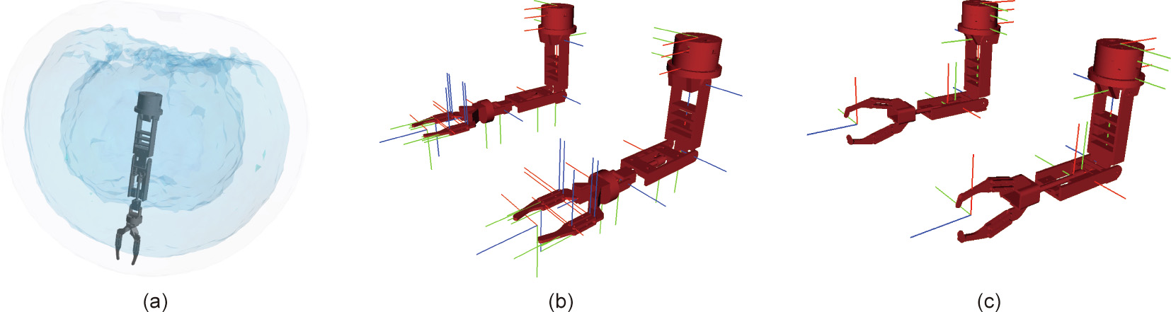
Fig. 2. Manipulators’ kinematic reachability and computer-aided design models for the online simulations and planning. (a) Kinematic reachability of the aerial manipulator; (b) 6-DoF arms model in OpenRAVE and coordinate frames; (c) 4-DoF arms model in OpenRAVE and coordinate frames.
As mentioned earlier, the UAV is equipped with an Intel RealSense D435 device. This device was chosen due to its capability to obtain reasonably accurate depth information outdoors. The depth information is exploited by the visual algorithm to obtain the 6D pose of the object for the manipulation process. This camera also provides excellent quality for short distances, as it is able to capture depth up close (up to 0.2 m), which makes it ideal for hand-eye coordination in manipulation tasks in robotics.
To conclude, Table 1 summarizes the specifications of the complete aerial system.
《Table 1》
Table 1 Platform specifications.

《3. Object detection and pose tracking》
3. Object detection and pose tracking
This section describes the algorithm used to detect and track the target object. Object detection is a challenging task. However, the use of deep learning techniques has revolutionized the way in which perception is conceived. The proposed methodology combines a convolutional neural network (CNN) with a random sample consensus algorithm to detect the object and compute its pose for the aerial manipulator. The algorithm is summarized in Fig. 3.
《Fig. 3》

Fig. 3. Scheme of the visual algorithm for the object detection and pose estimation of the target object. EKF: extended Kalman filter.
The algorithm is based on two stages. First, an object-detection CNN is applied to produce object candidates. Then, an alignment algorithm is used to compute the exact location of the target object.
CNNs are widely used nowadays and provide solutions to many difficult problems, as in the case of object detection. If the target object is known, only a labeled database of images is needed to train the network. However, these algorithms are heavy in mathematical operations, albeit highly parallelizable. Thus, GPUs are usually used because they are specifically designed to perform parallel operations efficiently. Some of the most used frameworks for this purpose are TensorFlow [43] and Caffe [44]. These frameworks provide an extensive ‘‘model zoo” with the implementation of the newest networks, thus speeding up the testing and development process. However, it is essential to consider that the final algorithm will be carried out by the onboard computer in the drone, which may have some limitations such as compute unified device architecture (CUDA) compatibility. In Section 6, a comparison between different algorithms (F-RCNN, SSD, and YOLO) on three different devices (a laptop computer with a GTX1070, a Jetson TX1 by Nvidia, and an Intel NUC computer) is presented.
The CNN is fed with RGB images provided by the camera. As a result, a set of candidate bounding boxes is obtained. The bounding box with the highest probability is employed to crop both the RGB and the depth images. These images are used to compute a local point cloud, combining the information from the pictures and the calibration matrices of the device. This colored point cloud is used in the next stage.
In short, the use of the object-detection algorithm reduces the search for the object during the alignment stage, decreasing the searchable area by 50%, and possibly by as much as 80% if the crawler represents a small fragment of the image.
At this point, a fragment of point cloud that contains the target object is obtained. In order to locate the object, an alignment algorithm is used. This algorithm filters the object from the background. A point cloud model of the crawler is provided to perform an iterative closest points (ICP)-based algorithm [45,46], which outputs the pose of the target. The ICP method uses all the available information to enhance the alignment process. It includes the 3D location of points (Eq. (1)), the normal information obtained from both the model and the scene (Eq. (2)), and the color data (Eq. (3)). This information is used in the form of outlier rejections during the selection process of points before the iterative calculation of the affine transformation.

where Ddist is the geometrical distance between any two points x1 and x2 of the point cloud.

where Dnorm means the cosine of the angle between the normals A1 and A2; A1 and A2 are the normals of any two points x1 and x2 of a point cloud, respectively.

where Dcolor means the absolute distance between the colors assigned to any two points x1 and x2 of a point cloud; R, G, and B are the values of the red, green, and blue channels, respectively.
It is worth noting that ICP algorithms are sensitive to the initial conditions. For this reason, the pose computed in the previous instant (k – 1) (k is the corresponding instant of the previous computed cloud) is used to provide a good estimate for the algorithm. This fact, together with the crop and clean of the input cloud, maximizes the probability of the algorithm converging to the correct solution.
Finally, the result of the algorithm is filtered by an extended Kalman filter (EKF) [47,48]. The filter helps to reduce the noise in the results and makes it possible to predict the relative speed of the object, which is used to improve the object pose estimation. A simple kinematic model was chosen to estimate the object’s state.
《4. Grasp planning》
4. Grasp planning
In order to make it possible to grasp the target object, a grasp planning algorithm was developed, composed of the following steps: First, a set of feasible grasps is generated, taking into account the target’s shape; next, these grasps are arranged according to their properties; finally, the best available grasp is chosen according to the computed visual information at each instant. During the grasping procedure, if the pose of the object makes the current grasp unreachable, the planner chooses the closest best grasp.
《4.1. Grasp generation》
4.1. Grasp generation
First, a set of possible contact points is generated on the surface of the target object. Our approach is based on the grasp generation algorithm described in Ref. [49]. This algorithm casts a set of rays from a bounding box toward the target object. Each ray collides once with the surface, and the surface normal is computed. An example is shown in Fig. 4.
《Fig. 4》
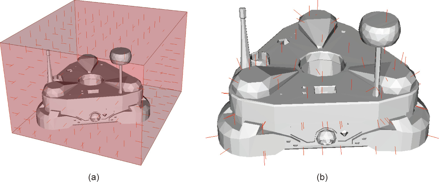
Fig. 4. Example of the ray-tracing algorithm for contact point calculation. (a) The initial set of rays used to compute the grasp points; (b) the resulting grasp points computing using the ray-tracing algorithm.
However, this methodology may fail to generate a feasible grasp for objects with complex shapes. Fig. 5 shows an example of the ray-tracing algorithm for a U-shaped object. It can be seen that if the aperture of the gripper is smaller than the size labeled as “a” in Fig. 5(b), then the object is ungraspable for the robot. However, if the algorithm takes into account all the possible internal nooks of the object’s surface, then the robot can grasp the object if the aperture of the gripper is larger than the sizes labeled as "b” or "d” in Fig. 5(b).
《Fig. 5》

Fig. 5. Example of the use of the grasping algorithm for a non-convex object. (a) An isometric view of the rays crossing the object; (b) the front view. Red lines represent the rays used to trace the possible grasp points.
In general terms, let p be a single ray passing through an object. The number of collisions of p with a mesh is Mcollisions = Mfolds × 2; thus, the number of combinations of opposite contact points that might generate a grasp are

where Mgrasps is the number of possible grasps; Mfolds corresponds to the folds intersected by the ray; j is the internal loop variable of the SUM operator.
This generation of contact point candidates may be time intensive if the mesh of the object is too complicated. In order to speed up this step of the algorithm, the contact points generated are stored in a binary file so they can be reused in any mission if the object is the same. Once this ray tracing is performed, the untransformed results are stored in a database; if the same object or a different instance of the same object is grasped later, this database is recovered, thus avoiding all the ray-tracing computations.
The set of contact points is then used to generate candidate grasps. The grasps are sampled in an internal simulator according to the pose of the object relative to the aerial manipulator. The algorithm computes the reachability for each grasp, the possible collisions between the manipulator and the target object, and the quality of each grasp. First, each arm samples all the possible candidate solutions to generate a list of feasible grasps for each arm. Next, all the feasible grasps are tested in pairs to obtain a list of dual grasps. The quality of these grasps is analyzed in terms of force closure and largest minimum resisted wrench, as described in Ref. [32]. All these grasps are then stored to be used during the planning process.
《4.2. Planning, servoing, and grasping》
4.2. Planning, servoing, and grasping
Once the list of grasps is arranged, the best grasp is chosen based on the current relative target object pose. This is the closest and most stable grasp for the dual manipulator. Before grasping, the arms are sent to a pre-catch position; this prevents the manipulators from performing large and dangerous movements, as it is crucial to prevent the manipulators from colliding with the flying components of the robot.
Let it be a multi-link robot manipulator L specified by the scalar variables  describing the states of its joints. The end of each link of the body has a certain position
  some of which are the so-called end-effectors. These positions can be described using the Denavit–Hartenberg (DH) formulation [50] as a chain of transformations between the joints of the manipulator and computed by a set of parameters
 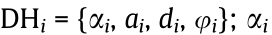 means the angle between the z axis of the joints,
  is the distance between the joints along the x axis of the first joint,
  is the distance between two joints along the z axis of the first joint,
  is the angle along the z axis of the first joint between the x axis of the joints. Each
  element is a matrix that transforms between link (
 – 1) to ; that is, it performs forward kinematics (FK).
The purpose is to obtain a set of adequate joints  that places the end-effectors on a target location
  ; that is, to perform inverse kinematics. This problem has been widely studied. Unfortunately, there is no straightforward solution in most situations. Iterative methods [51] and sampling methods [52] are perfectly suited to this problem. FK are given by functions
  that are
 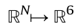 , which describes FK from an N dimensional space to the 6D space composed by the position and orientation of the end-effector of the manipulator. These functions can be linearly approximated using Jacobian matrices
  close to the current joint state
  The velocities can be expressed as follows:

where  represents the position of the end effector in terms of the joint space

where  is the partial derivative operator,
  is an specific joint of the joint space,
  is the position of the m link, m and n are the index iterators over the variables to define the complete Jacobian matrix .
The final purpose is to guide the arms toward the target grasps using the visual information from the sensors. In this work, a Jacobian damped-least square (DLS) gradient descent method [53,54] is applied to ensure the convergence of the arms toward the target position. This method has been shown to be more robust to inverse and pseudoinverse methods [54] near to instabilities and singularities in the Jacobian matrices. Let  and
and  be the target position of orientation for the end-effector given by the grasp planning and updated by the vision algorithm. The aim is to update the manipulator’s pose by updating its joints.
The DLS proceeds as follows: Eqs. (7) and (8) are computed based on the current state of the robot and the target pose of the end-effector; next, Eq. (9) is used to compute a vector that contains an increment in the joint values of the robot that allows the endeffector to move toward the target pose.

where Xtarget and Qtarget are the target positions for the endeffectors; and are the target position and orientation of the end-effector at instant K.

where  are the corresponding position and orientation Jacobians at the current state.

where  represents the arm angles of the current joints;
  is the damping coefficient to reduce the issues related to the inversion of the matrix. must be large enough to ensure that the algorithm behaves adequately close to singularities, but not too large to grant a good convergence rate. I means an identity matrix with the size of
  . These are calculated based on the position of the target object, which is computed in the vision module.
Furthermore, working with a pair of manipulators requires additional constraints. The principal constraint is the need to avoid collisions with itself and with other objects. However, checking the collisions of any non-convex object is not trivial. The use of a convex hull is advantageous in some situations, as it can be used to check them. However, this simplification can be rough in some applications. Modern approaches split the objects into a set of convex hulls [55,56]. This results in a more accurate solution while preserving the advantages and mathematical simplifications of working with convex hulls. In the present work, the implementation given by OpenRAVE is used [57], which integrates these fast methodologies.
Finally, it is possible that due to the oscillations of the aerial robot, or if the target object is mobile, the best grasp may became unreachable. The algorithm continuously measures the quality of the current grasp against the database of grasps in a separate thread, in order to overcome this issue. If the grasp became unreachable or unfeasible, the algorithm switches to a new best option.
《5. State machine and complete mission》
5. State machine and complete mission
The work presented in this paper covers the process starting from the take-off of the UAV from the platform until its landing after grasping the target object. Such a complete mission requires a sophisticated system design. The system is composed of five modules, as shown in Figs. 6 and 7. Each module is responsible for a single task in the UAV. In order to simplify the development process, communication between modules is carried out by ROS [58]. In this section, each module is initialized in an idle state that is triggered by a global signal start.
《Fig. 6》

Fig. 6. First two submodules of the system. (a) Global state machine; (b) UAV control state machine.
《Fig. 7》

Fig. 7. First three submodules of the system. (a) Vision state machine; (b) grasp planner state machine; (c) arms controller state machine.
Fig. 6(a) shows the global state machine, which is responsible for the global behavior of the mission. It is composed of three states: approaching, grasping, and homing. Approaching triggers the take_off signal and waits until the UAV has taken off. After that, the global state machine sends the approaching signal, which carries an initial waypoint, to the UAV’s controller, close to the target object. Once the UAV is in the target position, it holds until the target object is found (found signal). Then the state machine switches to the grasping state, in which the visual servoing comes into action to grasp the target. Once the object is grasped, the state machine switches to the homing state, which ends when the UAV lands.
Fig. 6(b) shows the state machine of the UAV’s controller, which consists of six states. It starts with idle. Once the UAV takes off, it keeps hovering until the next signal. If the global state machine sends an approaching signal, the UAV control state machine switches to the waypoint state and moves the UAV to a target position. If the object is found, it then switches to the tracking state. The tracking module is responsible for checking if the target object is in a reasonable position to be grasped. If so, it sends the near signal. This state finishes when the object is either lost or grasped.
Fig. 7(a) shows the vision state machine, which has the simplest structure. This state machine continuously runs the vision algorithm in order to detect the target object and compute its pose. When the object is found and its pose is computed, the state machine publishes that information together with the found signal. If the object is lost, then the lost signal is sent to cause the appropriate effect.
Fig. 7(b) shows the state machine of the grasp planner module, which is responsible for computing the appropriate grasps of the object. It also runs the servoing algorithm to compute the desired joints of the arms according to the target grasp. It starts by estimating the arranged list of grasps. Later, if the object is close, within the range of the arms, the state machine switches to the servoing state, in which the visual servoing publishes the target joints for the arms. As mentioned in Section 4, the arms are not sent directly to the grasping pose. Instead, they are sent to a position close to it, called the ‘‘approaching pose.” Once the arms are in the approaching position, the state machine toggles to the grasping state in which the arms move quickly toward the object and grasp it.
Finally, Fig. 7(c) shows the arms controller state machine. The manipulator controller is responsible for publishing information about the manipulators and providing the interface for moving them. It also limits the speed and trajectories of the arms to ensure that they are safe. An emergency stop (E_S) state has been placed to stop the arms externally for the sake of security. Emergency stop also causes the UAV to keep hovering to prevent it from crashing.
《6. Experiments》
6. Experiments
This section begins by describing the experiments that were performed to evaluate and validate the system and algorithms. Next, a set of experiments are described and discussed to show the performance of the system in carrying out aerial manipulation tasks. As mentioned earlier, this work focuses on grasping a crawler robot that was developed during the project AEROARMS, and that is used for pipe inspection in factories. However, the algorithm can be used equally well for any object, as neither the vision algorithm nor the planning process have any particular restriction to this particular object. A summary video of the experiments can be found.↑
↑ https://youtu.be/nXYlzqwM8kA.
《6.1. System evaluation》
6.1. System evaluation
As described in Section 3, an object-detection CNN is used in the first stage of the vision algorithm to detect the object. This provides a good initial solution for the alignment algorithm, which is more computationally expensive.
Three CNNs were tested in three different devices to choose the best option that fits the system requirements for the manipulation task and the payload limitations of the aerial manipulator. The specific CNNs tested were F-RCNN, SSD300, and YOLO (tiny YOLO v2). These were tested in the following three devices: a laptop with a GTX1070, a Jetson TX1, and an Intel NUC with an iris GPU. The first two devices have CUDA capabilities, as they have Nvidia GPUs. However, the third device cannot use common frameworks due to a lack of CUDA compatibility. Table 2 summarizes the average computational times of the different detection algorithms in the different devices. As the Intel NUC is not CUDA compatible, only the YOLO was evaluated. To be specific, an OpenCL implementation of the YOLO has been used.↑
↑ https://github.com/ganyc717/Darknet-On-OpenCL.
《Table 2》
Table 2 Computational time in seconds of the different algorithms in the tested devices.

kes the results of the other devices. However, due to the strict payload limitations, only the other two devices can be considered when operating with UAVs. At first, the YOLO runs a bit faster in the Jetson TX1 device. However, the central processing unit (CPU) capabilities of the Intel NUC computer strongly overtake those of the Jetson. As the whole system requires many processes from the rest of algorithms, the Intel NUC platform was selected.
The main benefit of the region proposal algorithm (the CNN) is that it drastically reduces the size of the cloud to be used in the alignment process (within 50% and 80%). It has a double improvement in that it decreases the computational time of this step, while also allowing the algorithm to converge a good solution; as gradient descent algorithms are usually sensitive to outliers and initial conditions, this improves convergence to the minimum.
Once the object is detected and its pose is estimated, the algorithm performs the grasp planning process described in Section 4. This process can be split into three stages. The first stage is the computation of contact points; this process can be precomputed, as it only depends on the resolution chosen for the algorithm and the model of the object. The second stage is the computation of feasible grasps for each arm separately. Table 3 summarizes the average computation times for each stage for various objects. Finally, the grasps are taken in pairs to arrange them by their quality metrics. The second column evaluates the time spent in the generation of the initial set of contact points. The grid resolution is the distance between the initial set of rays used during the ray tracing evaluation as described in Section 4.1. The third column shows the time spent evaluating the feasibility of the grasps generated in the previous step. Eventually, the fourth column shows the time spent evaluating the quality of the grasps.
《Table 3》
Table 3 Computational times per mesh faces for grasp planning process.
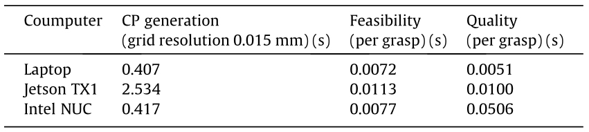
CP: contact point.
In order to prevent the arms from colliding with any part of the aerial platform, a safe volume is left above the shoulders of the arms. This volume corresponds to the flying parts of the robot, which must never be collided with. For safety reasons, this volume is taken into account in the planning process and during the servoing algorithm.
Fig. 8 shows a sequence of the online simulations run in OpenRAVE for the grasp planning process. Afterwards, the set of feasible grasps is stored for later use during the re-planning stage.
《Fig. 8》

Fig. 8. Different samples of the grasp planning process.
《6.2. Simulated and test-bench experiments》
6.2. Simulated and test-bench experiments
In order to verify the performance of the arms and their control before the actual experiments, a set of simulations was carried out. The pose of the objects to be grasped was given with a certain noise. These objects were then animated to stress the arm servoing algorithm. Three objects were shown with different shapes. However, any other object can be chosen at this stage, as the algorithm is capable of computing a grasp for any mesh.
Fig. 9 shows a sequence of snapshots of the simulated experiments to demonstrate the reachability of the arms in different situations. In these simulation experiments, the algorithm proceeds as in the real experiments, but the pose of the object is provided by the simulator, with a certain level of noise. First, the algorithm computes a set of feasible grasps, as described in Section 4.1. Next, according to the position of the object, it chooses the best grasp and guides the arm toward the object, as described in Section 4.2. Once the arms are close to the grasping poses, the system sends a signal to close the gripper.
《Fig. 9》

Fig. 9. Samples of simulation tests with different objects at different times.
The purpose of these experiments was to demonstrate that regardless of the vision, the algorithm is able to handle different objects and shapes. It generates a set of feasible grasps and dynamically chooses the best option based on the estimation of the object pose.
Before the real flights, the complete system—including the vision—was tested on a test-bench (Fig. 10), where the aerial manipulator was placed in a fixed structure and the target object was moved.
《Fig. 10》
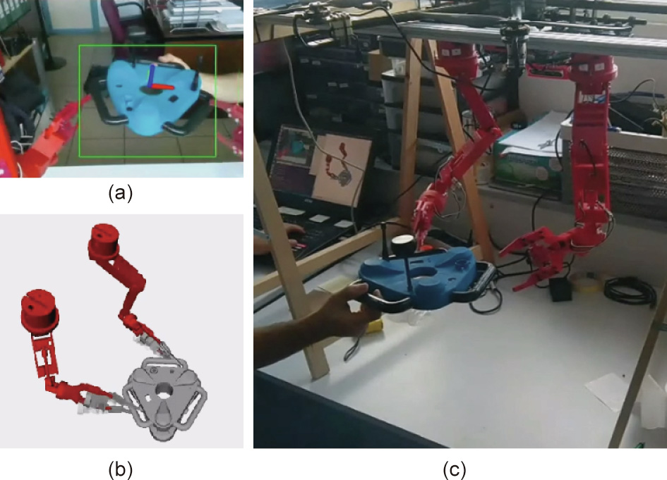
Fig. 10. Testing the complete system at the indoor test-bench. (a) The camera view and the 2D detection of the crawler mock-up; (b) the 3D virtualization of the robot, including the estimated position of the crawler and the target grasps; (c) a thirdview of the experiment.
《6.3. Flying experiments》
6.3. Flying experiments
This section describes the experiments that were carried out to demonstrate the performance of the system in real environments. For these experiments, a mock-up of a crawler robot was 3D printed. Two different setups were prepared. In the first setup, which was indoors, the UAV performed a completely autonomous operation, thanks to the position obtained by a MOCAP system. The second setup was intended to test the system outdoors. In both experiments, the 4-DoF gripper was chosen, as it is stronger than the 6-DoF version.
The first key module is the vision system, which computes the pose of the object to be grasped for the grasp planning, feeds the arms module for the servoing, and provides a reference position for the UAV. Fig. 11 shows the results of the algorithm. Fig. 11 (a) shows the result of the object detection in the RGB image using the CNN. Fig. 11(b) shows the fragment of the point cloud computed using the depth image and the estimation of the object’s pose from the alignment algorithm, filtered by the Kalman filter. The pose estimation is highlighted with an overlaid red point cloud and a coordinate system, as shown in the figure.
《Fig. 11》

Fig. 11. Object detection and pose estimation results. (a) A bound box resulting from YOLO; (b) the fragment of cloud and the pose estimation as an overlaid red-dots model and a coordinate frame.
Fig. 12 shows the estimation of the object’s pose from the vision system against the ground truth using a MOCAP system. The estimation shows an average of the root mean square error (RMSE) smaller than 0.02 m. This accuracy is fundamental to ensure that the robot can perform the grasp tasks. Larger errors in the estimation of the localization of the robot would be problematic, causing the robot to miss the grasp and even collide with the environment.
《Fig. 12》
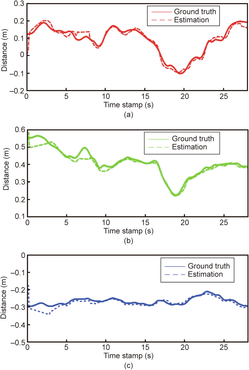
Fig. 12. Estimated pose of the crawler versus the ground truth in the UAV’s coordinate system. (a) Estimated distance from the camera vs. ground truth in the X axis; (b) estimated distance from the camera vs. ground truth in the Y axis; (c) estimated distance from the camera vs. ground truth in the Z axis.
Fig. 13 shows an additional experiment for testing the visual detection module. In this experiment, the mock-up was moved along a pipe. The position of both the UAV and the crawler was measured by the vision system and a MOCAP system.
《Fig. 13》
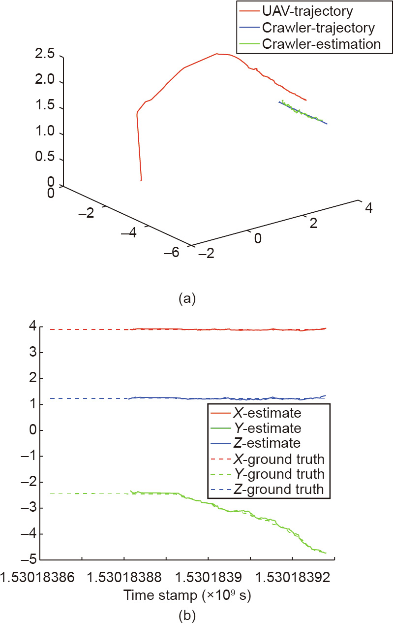
Fig. 13. Trajectory of the UAV and estimated position of the crawler measured by the vision system in global coordinates (solid lines) and ground truth (dashed lines). (a) 3D trajectory of the UAV and the crawler during a moving experiment; (b) estimated position vs. real position of the crawler using the visual estimation in each of the axis.
The accuracy of the system was tested firstly indoors in a controlled environment with a MOCAP system. The mission started with the UAV taking off; the UAV then performed the pipeline maneuver explained in Section 5. Fig. 14 provides a snapshot of the experiment.
《Fig. 14》
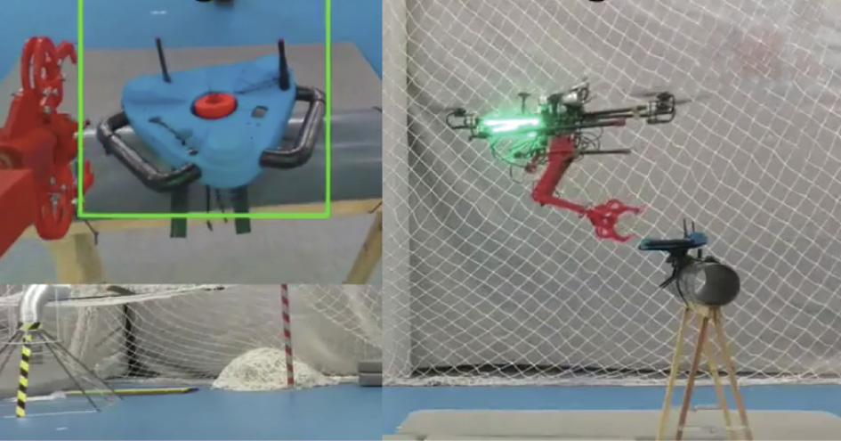
Fig. 14. Indoor autonomous mission using the MOCAP system.
Fig. 15 shows the values of the joints during two visual servoing tests. The dashed line corresponds to the target joints and the solid line corresponds to the actual joints values. The figure shows how the system switches to a new grasp when the previous grasp becomes unreachable.
《Fig. 15》

Fig. 15. Joints values during the experiments (in radians). At first, the arms follow the grasp target. After a certain point, the object rotates, so the system switches to another feasible grasp.
Finally, Fig. 16 provides a photograph of the outdoors experimental test-bench. In this experiment, the UAV flew while being tied to a structure with a safety rope, for safety reasons. The photograph shows the point of view of the robot while grasping the mock-up of the crawler. This experiment demonstrated that the perception algorithm works outdoors using the RealSense Depth camera, regardless of the sunlight conditions.
《Fig. 16》
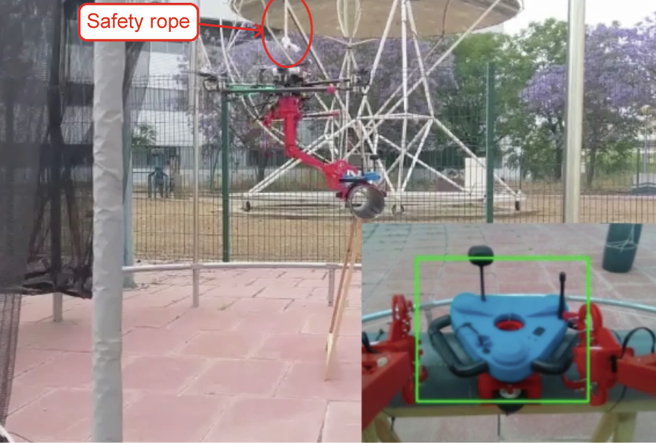
Fig. 16. Outdoor autonomous test with a safety rope.
《7. Conclusions》
7. Conclusions
This paper presents a complete system for performing manipulation operations with an aerial platform. Integrating two manipulators, instead of just one, makes it possible to grasp larger and more complex objects. In addition, having two manipulators helps the UAV to cancel fluctuations due to external disturbances and even choose grasps that are more stable because they enclose the center of mass. Both qualitative and quantitative experimental data have been provided in order to demonstrate that the system is capable of performing grasping operations.
The average RMSE of the vision system is lower than 0.02 m. The use of object-detection networks has been shown to be highly beneficial for the speed of the pose estimation. The main limitations come from the available onboard devices. Most state-ofthe-art CNNs have been tested and designed to be used in powerful computers, which makes it challenging to integrate them in aerial platforms. However, after the analysis in Section 6, the chosen algorithm provided fair enough results for the mission. The next step will include the estimation of object pose in the neuronal network.
It has been demonstrated in several environments that the system is able to operate and grasp the target object. In addition, these results have been supported with simulated objects in order to prove that the grasp planning algorithm is able to plan manipulation tasks with other shapes. The vision system has been tested under low-light conditions as well as outdoors under direct sunlight. The algorithm ran correctly under both illumination conditions.
《Acknowledgement》
Acknowledgement
This work was carried out in the framework of the AEROARMS (SI-1439/2015) EU-funded project and the national project ARMEXTENDED (DPI2017-89790-R).
《Compliance with ethics guidelines》
Compliance with ethics guidelines
Pablo Ramon-Soria, Begoña C. Arrue, and Anibal Ollero declare that they have no conflict of interest or financial conflicts to disclose.


 京公网安备 11010502051620号


