
《1. Introduction》
1. Introduction
Pervaporation (PV) is considered to be a promising membrane process due to its advantages of high energy efficiency and flexible operation [1]. This versatile process can be used in various liquid separations, especially for solvents dehydration, volatile organic compounds (VOCs) recovery, and separation of organic mixtures [2,3]. For practical applications, composite membranes consisting of a thin separation layer on top of a porous support have been widely studied. Most of these composite membranes are supported by porous polymeric substrates [4–7]. In recent decades, inorganic-supported composite membranes have been of great interest [8] because of the excellent chemical, mechanical, and thermal stability of inorganic substrates. Our group has developed a kind of ceramic-supported polymeric membrane for biofuel recovery [9–12], dehydration of solvents [13], desulfurization of gasoline [14], and reaction-integrated processes [15,16]. It has been demonstrated that this type of PV membrane exhibits a good and stable performance due to the confinement effect of the polymer/ceramic interface [17]. The rigid ceramic substrate can decrease the configurational space available for the polymer to perform translational motions. Thus, the polymeric layer and the ceramic layer underneath do not swell in a coordinated manner, resulting in asymmetric swelling in the polymer/ceramic composite membrane. The reduced swelling of the polymeric layer can improve the membrane separation performance and stability.
In addition to improving the membrane material, many recent works have demonstrated that membrane performance can be enhanced by optimizing the membrane configuration. Hollow fibers (HFs), which feature high-packing density, low transport resistance, and a self-supporting structure, have been widely studied for PV and gas separation [18–20]. In our previous work, we constructed a high-performance ceramic HF-supported polymer composite membrane by dip-coating a thin and defectfree polymer layer onto the outer surface of a porous ceramic HF [19,21]. Meanwhile, by optimizing the cross-sectional configuration and packing density, HF modules were designed in order to apply these composite membranes to the PV process [22]. Until now, most efforts have focused on the deposition of a polymeric separation layer on the outer (rather than inner) surface of HF substrates [20,21,23]. In view of industrial applications, HF composite membranes with an inner separation layer are more attractive because the inner separation layer is protected from physical damage during handling operations. Furthermore, the innersurface technology can be extended to develop a multi-channel composite membrane, which offers great potential for large-scale implementation, since it provides extra packing density and mechanical strength [24].
Along with other researchers, our group reported the preparation of porous crystals including zeolite [25] and metal organic frameworks (MOFs) [26,27] on the inner surface of HFs via various crystal growth approaches. However, coating a polymeric layer on the inner surface of a HF is still a great challenge, despite the few attempts that have been reported [28,29]. Wang et al. [28] developed a layer-by-layer self-assembly method that requires oppositely charged polymers to prepare polyelectrolyte HF composite membranes. They also reported the creation of an inner-skin HF polydimethylsiloxane (PDMS)/polysulfone membrane via dynamic coating [29]. Unfortunately, the prepared PDMS membranes exhibited relatively low flux and selectivity. The formation of a thin and defect-free layer might be disturbed by the continuous fluid. It is difficult to process a viscous polymer solution in the lumen of an HF using the conventional dip-coating method that is often used for tubes, because the flow of the viscous fluid can be restricted by the limited space of the HF bore. Meanwhile, the formation of a uniform and continuous polymer coating with a controlled thickness on the inner surface of an HF would lead to several challenges. It is essential to tune the rheological properties of the polymer solution, the bore-side nanostructures of the HF, and the interfacial characteristics in order to form integrated HF composite membranes.
In this article, we propose a coating/cross-flow method to fabricate a polymeric layer on the inner surface of a ceramic HF. The first coating process provides the polymer solution with a sufficient yet stable contact with the HF substrate in order to form a desirable interface and separation layer. The second cross-flow procedure is used to remove the excess coating in order to produce a uniform and thin layer. We demonstrated this methodology by preparing PDMS, the most representative hydrophobic membrane material for PV, on the lumen of a ceramic HF. The membrane morphology and separation performance were optimized by controlling the PDMS concentration and coating time. The methodology for fabricating a PDMS membrane on the inner surface of an HF was then extended from a single-channel HF to a multi-channel HF (Fig. 1). The interfacial adhesion between the PDMS layer and the HF substrate was evaluated by the in situ nano-indentation/scratch technique. The separation performance of the as-prepared inner-surface PDMS/ceramic HF composite membranes was evaluated by means of the PV recovery of n-butanol from a water solution. The effects of feed concentration, operating temperature, and long-term operation on the PV performance were systematically investigated.
《Fig. 1》
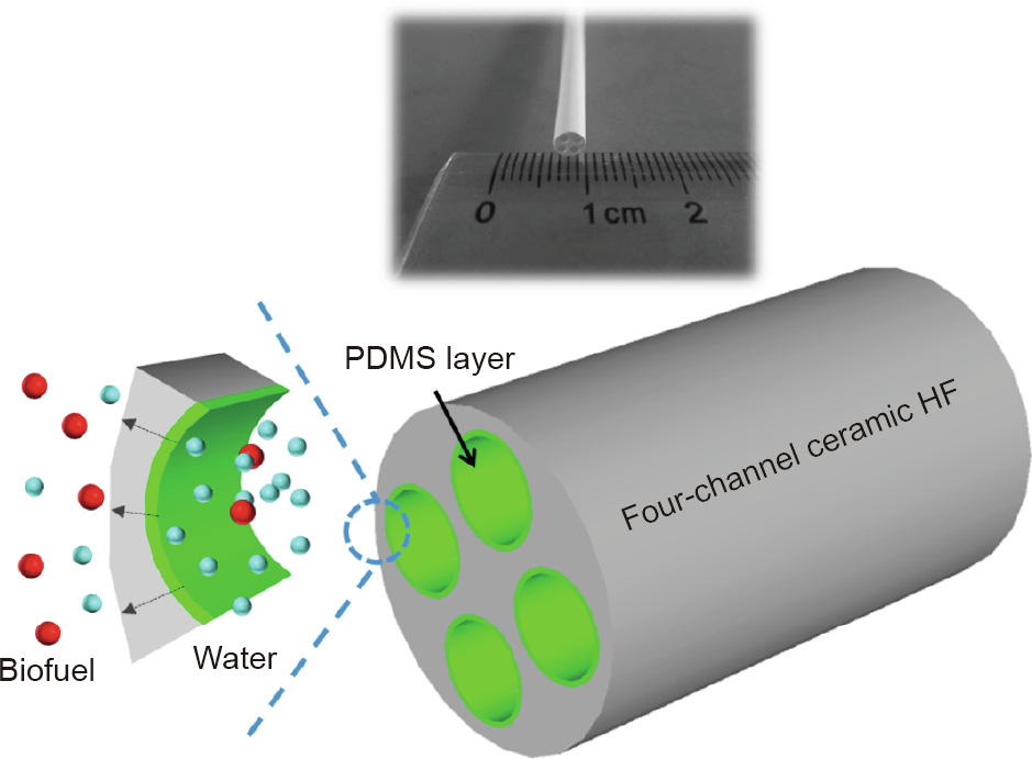
Fig. 1. A PDMS composite membrane prepared on the inner surface of a multichannel ceramic HF and its application for biofuel recovery from water.
《2. Experiments》
2. Experiments
《2.1. Membrane preparation》
2.1. Membrane preparation
Polyvinyl pyrrolidone (PVP), N-methyl-2-pyrrolidone (NMP), polyethersulfone (PESf), and alumina powders (particle size: 300 nm, Alfa-Aesar, USA) were mixed with a weight ratio of 2:28:10:60 and degassed to form the spinning dope. 30:70 w/w NMP/water was used as the bore fluid. The dope and bore fluid were co-extruded using a syringe pump (KD Scientific, USA) through a single-channel spinneret (orifice diameter of 1.2 mm) into water with an air gap of 2 cm. The spun fibers were dried at 100 °C for 12 h and sintered at 1200 °C for 12 h to form the final single-channel ceramic HF substrate. By using a tetra-bore spinneret with an orifice diameter of 4.8 mm (the diameter of the four bores is 1.2 mm each), a multi-channel ceramic HF was prepared by following the same compositions for the dope and bore fluid, as well as the same conditions for the spinning, drying, and sintering process. The details of the dope preparation and spinning can be found in previous work [30,31].
PDMS ( -dihydroxy polydimethylsiloxane, molar mass: 5600 g·mol-1 , Sigma-Aldrich, USA) polymer was dissolved in n-heptane; the cross-linker tetraethylorthosilicate (TEOS) and the catalyst dibutyltin dilaurate were then added with a weight ratio of 100:10:1 for the PDMS/TEOS/catalyst. After pre-polymerization for 24 h, the PDMS solution was coated on the lumen of the vertically placed ceramic HF via a coating/cross-flow method with the following two steps:
(1) Static coating: The PDMS solution was injected into the bore side of the ceramic HF and kept stable for the required time.
(2) Cross-flow: The PDMS solution in the lumen of the HF substrate was simply extracted by a syringe. The injection and extraction rate of the PDMS solution was precisely controlled at 60 mL·min-1 using a syringe pump. For comparison, another two coating methods were carried out:
(1) Static coating: The PDMS solution was injected into the bore side of the ceramic HF. After keeping it stable for the required time, the solution was discharged.
(2) Cycled flow coating: The PDMS solution was circulated in the bore side of the ceramic HF by a peristaltic pump with a flow rate of 60 mLmin1 . The coating time was controlled by the cycled flowing time.
The PDMS-coated ceramic HFs were dried at 25 °C for 24 h, and then heat treated at 120 °C for 12 h to obtain the inner-surface PDMS/ceramic HF composite membranes.
《2.2. Characterizations》
2.2. Characterizations
Attenuated total reflection Fourier-transform infrared (ATR-FTIR) spectra (AVATAR 360, Thermo Nicolet, USA) were recorded from 4000 to 400 cm-1 with 32 scans and 4 cm-1 resolution for the PDMS dense film, ceramic HF, or PDMS/ceramic HF composite membrane. Membrane morphology was examined by a field-emission scanning electron microscope (FE-SEM, Hitachi S-4800, Hitachi, Japan). The interfacial adhesion of the composite membrane was measured by the nano-indentation/scratch technique using a NanoTest system (NanoTestTM, Micro Materials, UK), as reported in our recent work [32].
《2.3. PV measurement》
2.3. PV measurement
The separation performance of the composite membrane was evaluated by means of PV process [14]. The effective length of the PDMS/ceramic HF composite membrane in the module was 5.8 cm, with effective membrane areas of 1.82 and 7.28 cm2 for the single-channel and multi-channel membranes, respectively. The n-butanol/water mixtures were fed into the membrane bore side using a peristaltic pump, while the membrane shell side was vacuumed below 450 Pa. A water bath was used to maintain a given feed temperature. Permeate vapor was collected by cold traps using liquid nitrogen (N2). The n-butanol concentration was analyzed by a gas chromatograph (GC-2014, Shimadzu, Japan) with a thermal conductivity detector (TCD). The internal standard method using iso-butanol was employed to quantify the n-butanol concentration. The permeate sample was sometimes diluted with water to produce a homogeneous solution for the gas chromatograph injection. PV separation performance is often expressed in terms of total flux J and separation factor β, calculated as follows

where M is the weight of the permeate, A is the effective membrane area, and t is the permeation time interval.

where X and Y are the mass fractions of the component i or j in the feed and permeate, respectively.
《3. Results and discussion》
3. Results and discussion
《3.1. Membrane preparation》
3.1. Membrane preparation
3.1.1. Ceramic HF substrate
The nanostructures of the HF play a significant role in determining the formation of the polymeric layer of the porous substrate. The ceramic HF substrates used here were fabricated by means of the phase-inversion and sintering method [31,33]. Fig. 2(a) shows a digital picture of the prepared porous singlechannel ceramic HFs. The average pore size, porosity, and N2 permeance of the ceramic HF substrate were 200 nm, 43.5%, and 4.2 × 10⁵ mol·m-2 Pa-1 , respectively. An asymmetric fiber structure was designed for the purpose of inner-surface polymer coating. As shown in Fig. 2(b), a finger-like structure was located at the outer side of the fiber wall, while a sponge-like structure was located at the inner side of the wall, whose total thickness was about 300 μm. The finger-like structure, which has a higher porosity and lower transport resistance, acts as an ideal support for the composite structure [19], while the sponge-like structure (Figs. 2(c) and (d)) provides a relatively dense and smooth inner surface for the coating of the polymer solution and the formation of a thin layer [20]. These featured nanostructures of the inner surface are beneficial for controlling the degree of polymer solution penetration and obtaining a thinly coated layer with minimum defects.
《Fig. 2》

Fig. 2. Morphologies of the single-channel ceramic HF substrate. (a) Digital photo; (b) SEM images of the cross-section; (c) the inner surface; (d) the enlarged inner edge.
3.1.2. Formation of PDMS layer on the HF inner surface
As reported in our previous work [9,13,19,21], polymeric separation layers can be successfully deposited on the outer surface of a tubular or HF substrate via a conventional dip-coating method. However, it is difficult to use the same method to coat an integrated polymeric layer on the inner surface of an HF, presumably due to the low accessibility of the viscous polymer solution to the fiber’s bore side. Kosaraju and Sirkar [34] proposed an interfacial polymerization method to prepare a thin separation layer on a porous polypropylene substrate for solvent-resistant nanofiltration, in which monomer solutions were alternatively passed through the lumen side. However, that approach was based on two assumptions regarding the coating solution—namely, reactivity and low viscosity, which cannot be found in most polymer-coated PV membranes.
In the present work, a coating/cross-flow method is proposed for polymer coating on the inner surface of an HF. Two typical methods (static coating and cycled flow coating) were also studied for comparison. As shown in Fig. 3, the cross-linked PDMS solution was filled in the bore side of the HF. The polymer solution was adsorbed on the ceramic surface and then penetrated into the pores of the HF substrate to form a transition layer in the interface. After allowing a certain amount of time for static coating, a gentle cross-flow (controlled by a syringe) was introduced to remove the excess polymer solution within the fiber bores. Due to the strong interaction between the polymer chain and the porous ceramic fiber, a uniform and thin PDMS layer was obtained under the surface fluid flow (Fig. 3(b)). In comparison, in the absence of the cross-flow, the static coating method produced a very thick PDMS layer (> 500 μm) (Fig. 3(a)). The gravity effect of the polymer solution was insufficient to reduce the layer thickness or maintain an even coating. In contrast, in the cycled flow coating method, the polymer layer deposition was inhibited by the continuous surface cross-flow (generally controlled by a peristaltic pump), which led to the separation layer being too thin to prohibit the generation of defects. As displayed in Fig. 3(c), almost no PDMS layer was found on the inner surface of the HF coated by a cycled flow of polymer solution. Moreover, bubbles were generated in the polymer solution during the continuous fluid flow, which were prone to result in nonselective voids in the formed polymeric layer. In all, neither the excessively thick (Fig. 3(a)) nor thin PDMS (Fig. 3(c)) coated HFs could be expected to exhibit a good separation performance.
《Fig. 3》

Fig. 3. Comparison of different methods for preparing an inner-surface PDMS/ceramic HF composite membrane. (a) Static coating method; (b) coating/cross-flow method; (c) cycled flow coating method. Left: preparation schematic; right: cross-section SEM image(s) of HF; insert in part (c): fiber’s inner surface. Preparation conditions for all three methods: PDMS concentration of 10 wt%; coating time of 60 s.
During the coating/cross-flow approach, the coating process allowed adequate wetting and adsorption of the polymer solution on the ceramic surface. Meanwhile, a favorable polymer–ceramic interfacial layer was formed as the polymer solution penetrated into the ceramic pores [17]. Furthermore, the subsequent gentle cross-flow treatment redistributed the surface coating to result in a homogeneous polymeric layer, and controlled the layer within a desired thickness. By combining the two processes, the HF inner-surface coating technique could result in a thin and defectfree polymeric separation layer. A syringe pump can be applied to realize the coating/cross-flow approach for scalable fabrication.
The microstructures of the inner surface of the PDMS HF composite membrane prepared by the coating/cross-flow method were further investigated by SEM characterization. As shown in Fig. 4, a smooth, defect-free PDMS layer was obtained on the inner surface of the single-channel ceramic HF substrate. There was a clear transition layer between the PDMS and the ceramic substrate, formed by the polymer solution penetrating into the porous HF supporting layer. This transition layer provided the composite membrane with sufficient interfacial adhesion, resulting in a PDMS layer that tightly covered the inner surface of the ceramic HF with no delamination [35].
《Fig. 4》

Fig. 4. Typical morphologies of the inner-surface PDMS/single-channel ceramic HF composite membrane. (a) Overall cross-section; (b) cross-section of membrane wall; (c) inner membrane surface; (d) inner membrane edge. Preparation conditions: PDMS concentration of 10 wt%; coating time of 60 s.
Using this coating/cross-flow method, we also successfully prepared a PDMS separation layer on the inner surface of a multichannel ceramic HF. As shown in Fig. 5, the HF exhibits a regular structure with a uniform distribution of four channels, providing much stronger mechanical strength, which will be discussed later. Each channel had a diameter of ~1 mm, and the surface of each was coated with a PDMS separation layer. The enlarged membrane cross-sectional SEM images showed a fiber wall consisting of macro-voids and sponge-like pores, which respectively offered low transport resistance and an even surface for the polymer coating. Like the single-channel HF composite membrane, an integrated and uniform PDMS layer was firmly adhered onto the inner surface of the multi-channel HF substrate.
《Fig. 5》
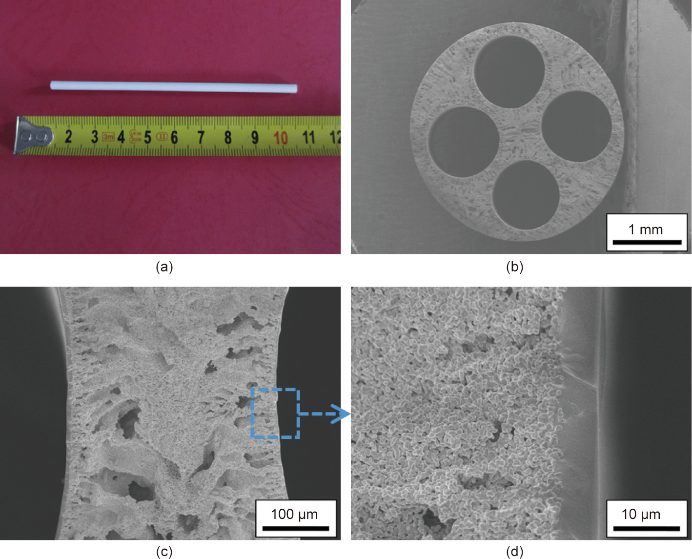
Fig. 5. Typical morphologies of the inner-surface PDMS/multi-channel ceramic HF composite membrane. (a) Digital photo; (b) SEM images of the overall cross-section; (c,d) the enlarged cross-sections. Preparation conditions: PDMS concentration of 10 wt%; coating time of 60 s.
In addition to the morphology observation, ATR-FTIR analysis was used to characterize the surface groups of the PDMS dense membrane, ceramic HF substrate, and PDMS/ceramic HF composite membrane. As shown in Fig. 6, the peaks that were observed at 1015, 1259, and 2963 cm-1 were attributed to the stretching vibration of Si–O–Si, the bending vibration of Si–CH3, and the stretching vibration of –CH3, respectively. These characteristic peaks of the PDMS material [9] further indicated a successful deposition of the PDMS layer onto the inner surface of the ceramic HF.
《Fig. 6》
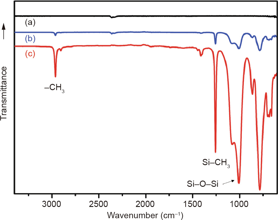
Fig. 6. ATR-FTIR spectra of (a) the ceramic HF substrate, (b) the inner-surface PDMS/ceramic HF composite membrane, (c) the PDMS dense membrane.
Interfacial adhesion is a key factor in the structural stability of composite membranes during practical separation application. We used a nano-indentation/scratch technique [32,35] to in situ probe the adhesive force of the PDMS layer to the HF substrate; the result is given in Fig. 7. According to our previous study [32], the corresponding critical load can be determined by the one-set of failure from the scratch–displacement curve and friction–displacement curve. The adhesion force of the PDMS layer onto the inner surface of the ceramic HF was 32 mN, which is as good as that of outer-surface PDMS/ceramic composite membranes (~35 mN) [32].
《Fig. 7》
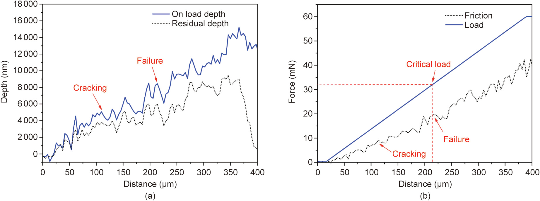
Fig. 7. Nano-indentation results of the inner-surface PDMS/ceramic HF composite membrane. (a) Scratch–displacement curve; (b) scratch load–displacement and friction–displacement curves.
3.1.3. Optimization of the preparation conditions
By further analyzing the preparation process of the innersurface PDMS HF composite membranes, two critical parameters were found to determine the final membrane structures and separation performance: ① the concentration of PDMS coating solution; and ② the static coating time. The polymer concentration greatly affects the rheological properties of the coating solution and the formation of the separation layer during the solvent evaporation process. In general, a thin polymer layer can be obtained by using a coating solution with a low polymer concentration [29]. However, it may be difficult to completely cover a porous substrate using an excessively dilute polymer solution. A coating solution with a low viscosity is prone to penetrating into the substrate pores and thus forming defects in the separation layer. Therefore, we studied the effect of PDMS concentration on the separation performance of our membranes. We took the single-channel HF composite membranes as an example. The membrane separation performance was evaluated by the recovery of n-butanol from its aqueous solution via PV, which is an important application for producing bio-butanol from the biomass fermentation process [12].
As shown in Fig. 8, the total flux of the composite membrane decreased gradually with an increase in PDMS concentration, which can be related to the reverse relationship between the membrane thickness and permeation flux. On the other hand, the separation factor showed a sharp rise (from 26 to 40) as the PDMS concentration increased from 5.0 wt% to 10.0 wt%, and then remained stable for a PDMS concentration greater than 10 wt%. This finding suggests that several nonselective defects—caused by excessive pore penetration of the polymer solution—were present in the separation layer prepared with the low PDMS concentration of 5.0 wt%. This membrane had a similar morphology to what is shown in the SEM images in Fig. 3(c), in which almost all of the PDMS solution penetrated into the porous substrate. As a result, a continuous separation layer was difficult to achieve. This problem can be avoided as the PDMS concentration reaches 10 wt%. The separation factor of 40 suggests the formation of a highquality separation layer on the HF inner surface. It was difficult to enhance this value by further increasing the PDMS concentration, since the separation performance was already approaching the intrinsic selectivity of the PDMS material [36]. Thus, in our case, 10 wt% was regarded as the optimal PDMS concentration to form a thin and defect-free PDMS separation layer on the inner surface of the ceramic HF.
《Fig. 8》

Fig. 8. Separation performance of the inner-surface PDMS/single-channel ceramic HF composite membrane for different PDMS concentrations. Preparation condition: coating time of 60 s; feed condition: 1 wt% n-butanol/water at 40 °C.
According to our previous studies [35], the wettability between the substrate surface and the polymer solution influences polymeric layer formation: First, the solution disperses on the inner surface of the ceramic HF; next, the solution penetrates into the pores of the support; and finally, the polymer layer is deposited onto the surface with the evaporation of the solvent. In general, complete wetting of the polymer solution on the ceramic surface is necessary in order to prepare a PDMS/ceramic composite membrane. The wetting process deserves particular attention for the lumen polymeric coating in HFs. Therefore, it was studied by varying the coating time; the effect of coating time on the separation performance is shown in Fig. 9. Interestingly, all of the samples prepared with different coating times exhibited a relatively high separation factor (> 35). This finding suggests that the HF inner surface can be fully covered by the PDMS immediately (in only 10 s, in our case), which may be due to the good wettability of the PDMS/heptane solution on the ceramic surface. It was also found that a composite membrane with a higher separation factor was formed by increasing the coating time, which relates to the degree of penetration of the polymer solution into the HF pores. As demonstrated in our previous work [17], PDMS penetration into the substrate pores can help in the subsequent formation of a top PDMS layer, improving the integrity of the PDMS layer and thus enhancing the membrane selectivity. However, the penetrationinduced higher transport resistance would lead to a loss of membrane flux.
《Fig. 9》

Fig. 9. Separation performance of the inner-surface PDMS/single-channel ceramic HF composite membrane for different coating times. Preparation condition: PDMS concentration of 10 wt%; feed conditions: 1 wt% n-butanol/water at 40 °C.
Furthermore, the uniformity of the inner-surface PDMS/ceramic HFs prepared with different PDMS concentrations or dip-coating times was checked by SEM characterization. Under the optimized preparation conditions, the membrane surface was found to be defect-free, and the cross-sectional PDMS layer was uniformly and firmly adhered onto the ceramic HF substrate. These morphologies were very similar to the SEM images shown in Fig. 4, and are thus not shown here. Overall, the thickness of the inner PDMS coating could be readily controlled by varying either the polymer concentration or the coating time. It should be noted that the transition layer becomes thicker when the polymer solution concentration is decreased and/or the coating time is increased. This results in additional transport resistance in the composite membranes, which would sacrifice the permeate flux, although it might be helpful for maintaining high selectivity. For a given separation system, it is possible to control the polymer concentration or/and coating time to obtain the desired membrane thickness corresponding to the required flux and selectivity.
In addition, we tried different flow rates for extracting the coating solution, and found that an appropriate flow rate (50–70 mL·min-1 in our case) should be used to achieve a sufficient extraction of the coating solution without excessively removing the coated layer. Otherwise, an excessively low or high flow rate would produce a thick or defective membrane layer. This is our preliminary result; more systematic optimization is still underway and will be reported in the future.
《3.2. Membrane application for bio-butanol recovery》
3.2. Membrane application for bio-butanol recovery
3.2.1. Effect of feed concentration
Fig. 10 illustrates the effect of the n-butanol concentration in the feed on the separation performance of the inner-surface PDMS HF composite membrane. A higher feed n-butanol concentration resulted in a much higher total flux while slightly lowering the separation factor. Due to the strong affinity between n-butanol and PDMS, the n-butanol could easy enter the free volumes (cavities) of the PDMS chains, resulting in swelling of the PDMS membrane. This phenomenon has been well demonstrated for PDMSbased membranes [37]. In this work, it was difficult to measure the degree of swelling of the PDMS layer on the composite membranes due to the significant effect of the support layer. Regardless, it is reasonable to speculate that as the n-butanol concentration increases, more n-butanol molecules are adsorbed within the polymer chains, increasing the degree of swelling of the PDMS separation layer. Another possible reason for the flux improvement is the improved driving force from the increased feed concentration [38]. Consequently, both the n-butanol and the water molecules permeated through the membrane more easily, causing the total flux to increase. Furthermore, the molecular kinetic diameter of water (~0.296 nm) is smaller than that of n-butanol (~0.505 nm), causing water molecules to diffuse more quickly than n-butanol molecules. Thus, a relatively low separation factor was obtained at a high concentration of n-butanol in the feed.
《Fig. 10》

Fig. 10. Separation performance of the inner-surface PDMS/ceramic HF composite membrane for different feed concentrations. (a) Single-channel; (b) multi-channel. Feed condition: n-butanol/water mixture at 40 °C.
3.2.2. Effect of feed temperature
As shown in Fig. 11, the total flux increased linearly with the increase of feed temperature. The total flux had a three-fold enhancement at 60 °C compared with that at 30 °C. This may be partially attributed to the larger free volumes of the PDMS membrane at the elevated temperature. Meanwhile, the higher temperature generated a greater vapor pressure difference and thus a greater driving force for transport. It was notable that the separation factor did not decrease much when the feed temperature was increased. This favorable response is due to the so-called ‘‘confinement effect” in the polymer/ceramic composite membrane, where the rigid ceramic substrate constrains the excessive swelling of the polymeric separation layer [9,19,21]. It is interesting to note that the swelling induced by the feed concentration had a different influence on the separation factor than that induced by the temperature (Fig. 10 vs. Fig. 11). We speculate that the higher butanol concentration had a more significant swelling effect on the PDMS layer compared with the higher separation temperature. The confinement effect of the ceramic substrate effectively suppressed the excessive swelling of the PDMS layer at a higher temperature, but did not completely overcome the swelling of the PDMS layer at a higher butanol concentration. Thus, the separation factor remained almost the same at the elevated temperature but showed a slight decline at the higher feed concentration. Overall, this desirable temperature-dependent separation performance suggests that the separation performance of the inner-surface PDMS/ceramic HF composite membrane can be greatly enhanced in practical application by simply increasing the feed temperature.
《Fig. 11》
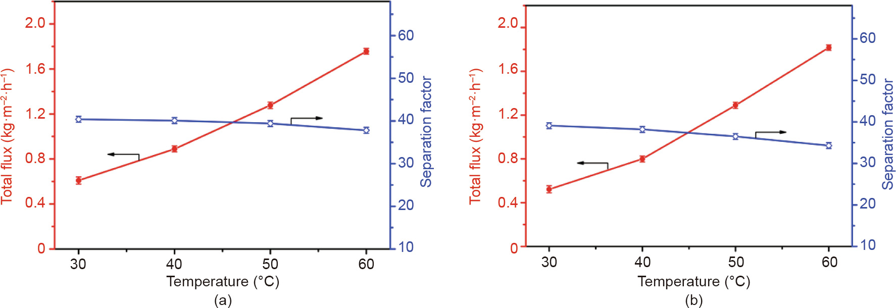
Fig. 11. Separation performance of the inner-surface PDMS/ceramic HF composite membrane for different feed temperatures. (a) Single-channel; (b) multi-channel. Feed condition: 1 wt% n-butanol/water.
3.2.3. Long-term stability
Membrane stability during long-term use is a key assessment criterion for practical PV application. As shown in Fig. 12, both the total flux and the separation factor of our inner-surface PDMS/ceramic HF composite membrane remained stable during 100–200 h of continuous operation. In this experiment, a membrane that is under high-speed cross-flow and a high vacuum might peel off, twist, or even break due to the elastic structure of the PDMS material. Nevertheless, due to the rigid structure of the ceramic HF substrate, the composite membrane exhibited excellent mechanical stability under such harsh conditions. Meanwhile, the controlled penetration of PDMS into the HF pores formed a transition layer between the polymer and the ceramic substrate, causing the thin and defect-free PDMS layer to tightly adhere onto the inner surface of the ceramic HF; this contributed to the highly stable performance of the composite membrane [17,19].
《Fig. 12》

Fig. 12. Long-term stability of the inner-surface PDMS/ceramic HF composite membrane. (a) Single-channel; (b) multi-channel. Feed conditions: 1 wt% n-butanol/water at 40 °C.
《3.3. Performance comparison》
3.3. Performance comparison
A performance comparison with the literature is provided in Table 1. Several types of hydrophobic membranes have been proposed for butanol recovery, including PDMS, poly(ether block amide) (PEBA), poly[1-(trimethylsilyl)-1-propyne] (PTMSP), and liquid membrane, in addition to inorganic zeolite, silica, and ceramic membranes. A thin separation layer generally obtains a high flux. Among these membrane types, PDMS is the representative membrane material due to its facile preparation and good, stable performance. Compared with the reported polymeric membranes and inorganic membranes, our inner-surface PDMS/ceramic HF composite membrane exhibited an outstanding butanol/water separation performance. A high flux and high separation factor were simultaneously achieved. In comparison with our previous work [10], the ceramic HF substrate contributed a much higher flux and better selectivity than the tubular ceramic substrate [19]. Given their high-packing density and easy fabrication, the highperformance PDMS HF composite membranes show great potential in application. Unlike polymeric membranes prepared on the outer surface, the inner-surface PDMS HF membrane can effectively avoid physical damage. Our future work will focus on minimizing the transport resistance of the HF substrate used for the innersurface polymer coating, in order to achieve a flux as high as that of the outer-surface-coated HF membrane.
《Table 1》
Table 1 Performance comparison of state-of-the-art membranes for PV separation of 1 wt% n-butanol/water mixtures.

BPPO: brominated polyphenylene oxide; PEI: polyether imide; PAN: polyacrylonitrile.
a Feed: 9.1 g·L-1 butanol, 2.25 g·L-1 acetone, 0.25 g·L-1 ethanol, 1.0 g·L-1 acetic acid, 1.0 g·L-1 butyric acid, 0.8 wt% acetone, 0.5 wt% ethanol.
b Feed: 5 wt% n-butanol.
c GFT PDMS membrane
d Feed: 1.5 wt% butanol.
It is also interesting to compare the properties of the innersurface PDMS/ceramic composite membranes using singlechannel and multi-channel HFs. On the one hand, the two membrane types exhibited similar transport properties in terms of total flux (~1800 g·m-2 h-1 ) and separation factor (35–38) for the PV separation of 1 wt% butanol/water separation at 60 °C (Table 1). This finding confirms the universality of our proposed coating/ cross-flow approach for fabricating a PDMS membrane on the inner surface of HF substrates. We used one fiber in the module to evaluate the performance of the single-channel membrane shown in Table 1. We also prepared four single-channel fibers in one module, which showed an almost identical PV performance as the module with one single-channel fiber. Since the PDMS separation layer is coated on the inner surface of the fiber, the feed flows through the bore side of the fiber, which is not significantly affected by the packing of the fibers in the module. As long as a sufficient vacuum is provided in the permeate side of the fiber (which was the case in this study), it is reasonable for this setup to result in a similar separation performance regardless of whether the module is filled with one or four single-channel fibers. On the other hand, with the highly integrated channels in one fiber, the multichannel HF (i.e., with four channels) provided a 74% higher packing density than the single-channel HF (Fig. 13(a)). Moreover, the multi-channel structure greatly enhanced the mechanical properties of the HF membrane, as evidenced by the 4.5 times higher breaking load that was achieved in the four-channel ceramic HFsupported PDMS composite membrane (Fig. 13(b)). Overall, the inner-surface PDMS/ceramic HF composite membranes presented in this work, which hold great potential for scalable fabrication and practical application, are a promising candidate for biobutanol recovery and organic compound enrichment applications.
《Fig. 13》

Fig. 13. Comparison of the inner-surface PDMS/ceramic composite membranes using single-channel and multi-channel HFs. (a) Cross-sections of an ideal packing pattern with the same membrane area of the PDMS layer, which requires four fibers for the single-channel HF, but only one fiber for the four-channel HF; (b) packing density calculated using the ideally designed patterns in part (a) and breaking load measured by the three-point method; inset shows a schematic of the measurement.
《4. Conclusions》
4. Conclusions
In this work, PDMS composite membranes were successfully fabricated on the inner surface of ceramic HFs via a coating/crossflow approach. The 10 wt% PDMS concentration and less than 60 s coating time were optimized to fabricate a thin and defect-free membrane layer. The prepared single-channel and multi-channel ceramic HF-supported PDMS membranes exhibited similar high fluxes of ~1800 g·m-2 h-1 and separation factors of 35–38 for 1 wt% n-butanol/water mixtures at 60 °C. Given its unique advantages of easy handling and high-packing density, the high-performance inner-surface PDMS/ceramic HF composite membrane is demonstrated to be a competitive candidate for the bio-fuels and organics production of industrial processes. Furthermore, the proposed coating/cross-flow method for preparing innersurface polymer-coated HFs opens a new route for the development of advanced membranes, adsorbents, and composite materials.
《Acknowledgements》
Acknowledgements
We acknowledge financial support from the National Key Basic Research Program (2017YFB0602500), the National Natural Science Foundation of China (21922805, 21776125, 21490585 and 51861135203), the Innovative Research Team Program by the Ministry of Education of China (IRT17R54), and the Topnotch Academic Programs Project of Jiangsu Higher Education Institutions (TAPP).
《Compliance with ethics guidelines》
Compliance with ethics guidelines
Ziye Dong, Haipeng Zhu, Yingting Hang, Gongping Liu, and Wanqin Jin declare that they have no conflict of interest or financial conflicts to disclose.


 京公网安备 11010502051620号


