

《1. Introduction》
1. Introduction
Exploring the moon has become a globally important task. One of the most important tasks in moon exploration is lunar landing, such as those achieved by Chang’e 3 (China) and Apollo 13 (USA). In the future, manned lunar landings will be carried out (China: 2025 [1–3]; USA: restart Apollo [4]). Here, the key technique lies in the trafficability characteristic of the lunar rover. That is, the newly designed lunar rover should be able to walk in the complex and harsh environment of the lunar surface. For example, the surface temperature of the moon can reach 150 °C in the daytime and drop as low as –180 °C at night, which makes the wheel technology used on earth difficult to use on the moon.
For this purpose, the wheel should have the following features: ① The lunar rover should be designed with high traction performance and carrying capacity [5–9]; and ② the rover wheel should be able to traverse obstacles [10]. There is an irregular distribution of rocks, craters, and slopes of different sizes and shapes on the surface of the moon [11–16]. The particle size and softness of lunar soil vary greatly [17].
In this regard, many kinds of wheel structure have been designed. Three have successfully landed on the moon: the elastic wheel of the former Soviet Lunokhod [18], the spring-griddle net wheel used by the American Apollo lunar roving vehicle (LRV) [4], shown in Fig. 1, and the Chinese YuTu [1,19–21], shown in Fig. 2. Other research results on wheel structure include the cylinder-conical wheel developed by Harbin Institute of Technology and the grip-hook and intelligent variable-diameter wheels designed by Beihang University, which have strong adaptability with the surface of the moon (Fig. 3) [22–24].
《Fig. 1》

Fig. 1. The Apollo LRV.
《Fig. 2》

Fig. 2. YuTu and spring-griddle net wheel.
《Fig. 3》

Fig. 3. The intelligent variable-diameter wheel.
Of these existing designed wheels, the spring-griddle net wheel is easily deformed when the load is extremely large, the cylinderconical wheel and the intelligent variable-diameter wheel are liable to fracture upon impact, and the grip-hook wheel has a complex structure and low reliability, so it is easily damaged. Furthermore, although these wheels have a strong ability to surmount obstacles, they are weak in power-consumption control and cannot meet the complex requirements of future lunar exploration projects [4]. Therefore, it is necessary to design new wheels with better balance.
To resolve these problems, a new wheel system is proposed. The system is based on the vane-telescopic walking wheel (Fig. 4), which was designed by the Intelligent Vehicle Group of Jilin University. This model was selected as the basis of our prototype, as it is suitable for lunar soft soil [25,26]. The most important merit of our new wheel system is that the wheel vane length can be adjusted automatically according to the road surface (i.e., softness and slope) and obstacles (i.e., size) [18].
《Fig. 4》

Fig. 4. Structure of vane-telescopic walking wheel.
For the vane-telescopic walking wheel, the longer the wheel vane is, the better the wheel passing performance is. Meanwhile, the greater the wheel rolling resistance is, the greater the energy consumption of the wheel is. Therefore, the ideal extension condition is for the wheel vane to protrude according to the terrain need, thus reducing the energy consumption [27].
In this study, a new wheel system is designed based on the following contributions, in order to pass through all kinds of road conditions on demand with the lowest energy consumption:
(1) A new vane-telescopic walking wheel is proposed for the lunar rover with a positive and negative quadrangle suspension.
(2) The parameters of the vane-telescopic walking wheel design are optimized.
(3) The prototype is evaluated in a simulated lunar soil environment.
(4) A new lunar rover prototype vehicle is designed and tested initially with the new wheel.
The remainder of this paper is organized as follows: Section 2 introduces the wheel force analysis for lunar rover wheels. Section 3 analyzes the parameter optimization of the vanetelescopic walking wheel design. Section 4 deals with the prototype evaluation in the simulated lunar soil environment. Section 5 concludes this paper and suggests several possible future works.
《2. Force analysis for lunar rover wheels》
2. Force analysis for lunar rover wheels
Before optimizing the vane-telescopic walking wheel, the lunar rover wheel is analyzed based on the actual conditions on the lunar surface; the dimension of the designed wheels can then be determined based on the analysis results [28]. The paper is based on a lunar rover model with a positive and negative quadrangle suspension, which was proposed by the Intelligent Vehicle Group of Jilin University.
In Fig. 5, L1 = 453.3 mm, L2 = 191.65 mm, L3 = 212.1 mm, L4 = 218.72 mm, L5 = 145.05 mm, L6 = 431.86 mm, L7 = 142.24 mm, L8 = 342.6 mm, L9 = 141.4 mm, L10 = 354.2 mm, L11 = 400.1 mm, L12 = 135 mm,  = 38.31,
  = 41.76,
  = 53.62,
  = 68.29,
  = 17.36,
  = 44.9,
  = 42.3,
  = 938.3 mm,
  = 359.5 mm,
  = 307.8 mm, and
  = 179.1 mm. Here, Li is the length of suspension; whose horizontal angle is represented by
  ; while
  means the length between two points. According to the design requirements of the mobile system, the wheel radius R is 150 mm, the single wheel mass is 3.5 kg, and the vehicle mass is 120 kg. Under the lunar gravity field, the weight of front (W1), middle (W2), and rear wheels (W3), W1 = W2 = W3 = 5.7 N, and gravity on one side of the load platform G = 80.85 N.
《Fig. 5》

Fig. 5. Suspension rod angles and key suspension dimensions of the model.
The key road condition for a lunar rover is slope. In many of the road conditions that a lunar rover must pass, the slope is the most intuitive and effective factor to reflect the wheel force condition. When a lunar rover is climbing, the wheel force condition is the most serious parameter, and the traction performance requirement for the wheel is the highest priority [29]. In this paper, the wheel force analysis is carried out with a slope angel of  degrees (Fig. 6).
《Fig. 6》

Fig. 6. The force of the mobile system on a road with a slope angel of .
The road’s supporting force Fv and the wheel’s pressure P are a pair of counterforces that have equal values and opposite directions. The friction force Fp and the slope resistance FRs are also a pair of counterforces. Therefore, the slope resistance and the pressure on the road of the lunar rover can be obtained, as shown in Table 1.
《Table 1》
Table 1 Slope resistance F Rs and pressure P with varying slope .

《3. Optimizing parameters determination of the vane-telescopic walking wheel》
3. Optimizing parameters determination of the vane-telescopic walking wheel
The most difficult challenge is the complex lunar environment, which consists of irregular stones and craters, varying slopes, and lunar soil with varying granularity and softness. Traditional wheels cannot fully deal with such an environment because their traction ability is insufficient to pull the lunar rover in soft lunar soil. To resolve this problem, a new type of wheel is designed that can automatically retract vanes according to the soil characteristics. First, the forces between the wheels and soil are analyzed below.
《3.1. Force analysis between the wheels and soil》
3.1. Force analysis between the wheels and soil
The force of the wheel can be divided into soil thrust (ST) and soil resistance (SR) according to the effectiveness of the force. If the ST is greater than the SR, the wheel will move forward. Otherwise, the wheel will rotate or remain stationary [30–33]. Here, SR includes four kinds of resistances: soil compaction resistance (SCR), soil bulldozing resistance (SBR), soil slope resistance (SSR), and soil vane resistance (SVR) [34]. The details of ST and four kinds of SR are introduced below.
3.1.1. Compaction resistance
During the wheel rolling process, the soil is extruded vertically downward. At the same time, the soil forces the wheel to prevent the vertical extrusion from forming the wheel compaction resistance. The compaction resistance FRc can be expressed as follows [35,36]:
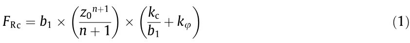
where z0 is the sinking depth of the wheel rim, z0 =  , kc is the cohesion modulus of the soil,
  is the friction modulus of the soil, n is the soil deformation index, b1 is the width of the wheel rim, D is the diameter of the wheel rim, and P is the pressure of the wheel on the soil.
3.1.2. Bulldozing resistance
Aside from vertical compaction, soil deformation is caused by the push forward of the wheels; this is the SBR bulldozing resistance, in which the soil in front of the wheels is wave shaped [37]. The bulldozing resistance F Rb can be expressed as follows:

where  ,
,
 =
=  is the bulk density, c is the cohesion force, and
  is the internal friction angle.
  are the Terzaghi bearing coefficients, which are related to ; their values are provided in Table 2 [38–40].
《Table 2》
Table 2 Terzaghi bearing coefficients.

3.1.3. Slope resistance
When the lunar rover climbs up a slope, the gravity in the direction of the slope creates the slope resistance [41], which can be expressed as follows:

where Wi is the weight of the ith wheel and is the slope angle.
3.1.4. Vane resistance
During the rolling process, the wheel vanes compress the soil vertically, and the soil prevents the vertical extrusion force from forming the vane compacting resistance, which is known as the vane resistance [42]. The vane resistance FRv can be expressed as follows:


where N is the number of vanes, b is the vane thickness, b2 is the vane width, S is the slip ratio of the wheel, and hb is the inserting depth of the vane. According to the sampling analysis of the lunar soil [43], the soil deformation index n is usually equal to 1, so the slip ratio index of the wheel S is n – 1 = 0. Thus, the vane resistance is not affected by the wheel slip ratio.
3.1.5. Soil thrust of the vane
The maximum ST received by the wheel rim, Fw, can be expressed as follows:

where A is the contact area between the wheel rim and the soil: A = 2 × b1 ×  .
.
The maximum ST received by the wheel vane, Fs , can be represented as follows:

where q is the pressure stress of the wheel rim on the soil, q = P/A,  is the flow value of the soil, and = tan2 (45° +
  ). According to Eqs. (1)–(6), the maximum traction force of the wheels, Fd ,can be expressed by Eq. (7).

《3.2. Optimizing parameters determination》
3.2. Optimizing parameters determination
Optimization of the vane spring, which is the most important feature for the performance of the lunar rover wheel, is our key work. In this study, the vane spring stiffness k and the spring initial torque T0 are calculated as the optimization variables so that the wheels can endure various road conditions while consuming the lowest amount of energy.
The optimizing parameters include the minimum of the inserting depth of the vane into soil when the wheels pass hb, the wheel rolling resistance torque Tf, the supporting force Fv, and the wheel friction force Fp. Some of the parameters are used as optimization constraints, and the others are used as the input of the optimization function. When calculating the above parameters, the following road conditions are analyzed: high, medium, and low soil passing ability; and a slope of 0°–3° [44].
By introducing the lunar soil parameters, the wheel parameters, and the wheel slope resistance FRs (Table 1), we can obtain the minimum inserting depth hb of the vane under various passing abilities of the soil and different degrees of the slope. The wheel pressure P (Table 1) and hb obtained above are then taken into the wheel resistance Eqs. (1), (2), and (4), and the wheel rolling resistance is obtained. The resistance is multiplied by the wheel radius R—that is, the wheel rolling resistance torque Tf. Table 3 shows the optimization parameters of the front wheel [45].
《Table 3》
Table 3 Optimization parameters of the front wheel.

《4. Optimization design and experiment with the new wheel》
4. Optimization design and experiment with the new wheel
As shown in Fig. 7, vane 5 (i = 5) is located at the bottom of the wheel, and mainly acts with the soil. Therefore, the extension of vane 5 is considered in the following analysis. The extended length of vane 5 can be expressed as Lo5( = 0°) = Loi (i = 5, = 0°), where the calculation of function Lo5 is detailed in the Appendix A. The objective function of the vane spring optimization is as follows:
(1) The requirement of high passing ability [46]:  = 0°,5°,…,30°.
(2) The requirement of reducing resistance and energy consumption [47]:  must be the minimum.
《Fig. 7》

Fig. 7. The position of the vane spring.
《4.1. Optimizing the design of the vane spring》
4.1. Optimizing the design of the vane spring
The optimization parameters obtained in Section 3.2, including Tf , Fp , Fv , and hb , are introduced into the above objective function to obtain Eq. (8).

where i represents 21 kinds of road conditions, which are composed of various slopes ( = 0°, 5°, 10°, 15°, 20°, 25°, and 30°) and soil passing abilities (high, medium, and low).

The spring stiffness k and initial torque value T0 of the front wheel vanes are then obtained. According to this calculation, they are k = 0.112 N·m·rad–1 (1 rad = 180°/π) and T0 = –0.038 N·m. A type of spring can be selected for the front wheel that can ensure the wheel’s passing performance in the complex moon environment. It can also reduce the energy consumption from the excessive overhang of vanes [48–50].
《4.2. Analysis of the optimization effect》
4.2. Analysis of the optimization effect
In the function Lo5, the rolling resistance torque Tf and the wheel friction Fp are always formed by Tf + R ×Fp. Tf + R ×Fp can be regarded as a variable, and is called the rolling friction force Tv. Thus, three variables in the original function Lo5 can be expressed in the form of two variables, Tv and Fv [51]. To analyze the mechanical properties for the front wheel optimization, k = 0.112 and T0 = 0.038 are introduced into the function Lo5(k, T0, Tf, Fp, Fv). The relationship between hb, Tv, and Fv can be obtained.
Fig. 8 shows the relationship among Lo5, Tv, and Fv for different slopes ( = 0°, °5, 10°, 15°, 20°, 25°, and 30°). It can be seen that the vane does not extend when Tv and Fv are small. When Tv and Fv reach a certain value, the vane starts to extend, and the vane extends more with an increase of Tv and Fv [52,53]. In Fig. 8, different colors represent different slopes; they do not coincide. This situation is mainly caused by the change in the contact point between the wheel and slope [54].
《Fig. 8》

Fig. 8. Relationship among Lo5, Tv, and Fv for different slopes of the front wheel.
Fig. 9 shows the relationship between the extension length Lo5 and the inserting depth hb. There are 21 values of the inserting depth hb. It can be seen that each value does not exceed its corresponding surface, which means that hb ≤ Lo5. This indicates that the vane-telescopic walking wheel can smoothly pass through the 21 kinds of road conditions [55,56]. In addition, it is clear that the maximum among the 21 values is in contact with its corresponding surface, which indicates that the wheel’s energy consumption has been reduced to the lowest level.
《Fig. 9》

Fig. 9. Relationship between the extension length Lo5 and the inserting depth hb.
Using the same optimization method, the spring stiffness k and initial torque value T0 of the middle wheel are k = 0.135 N·m·rad–1 and T0 = –0.023 N·m, and those of the rear wheel are k = 0.218 N·m·rad–1 and T0 = –0.128 N·m.
《4.3. Experiments with the vane-telescopic walking wheel》
4.3. Experiments with the vane-telescopic walking wheel
To test the actual performance and reliability of the vanetelescopic walking wheel, a prototype of the vane-telescopic walking wheel with the same dimensions was manufactured and installed on the lunar rover prototype CJ-1 (Fig. 10). An experiment on simulated lunar soil was carried out at the lunar surface simulation test field at the China Institute of Space Technology (Fig. 11).
《Fig. 10》

Fig. 10. Prototype of CJ-1.
《Fig. 11》

Fig. 11. Simulation on a lunar surface.
During the test, when the lunar rover normally runs in the soil, the length of the wheel vane increases to maintain proper thrust, as shown in Fig. 12(a). Then a horizontal force of 300 N is used to pull the wheel to simulate the resistance case. The vane continues to extend and the wheel traction is increased. The increased traction force overcomes the horizontal force so that the prototype can maintain the original speed, as shown in Fig. 12(b). When the horizontal force is gradually reduced, the vane is gradually restored to its original position, and the energy consumption is reduced, as shown in Fig. 12(c).
《Fig. 12》

Fig. 12. The vane extension. (a) The length of the vane increases when running in the soil; (b) the vane continues to extend when a horizontal force is used to pull the wheel; (c) the vane is restored when the horizontal force is reduced.
The experimental results show that the optimized vanetelescopic walking wheel can control the extension length of the vane according to the terrain resistance. Moreover, the energy consumption of the lunar rover can be effectively controlled when it passes through a complex road.
《5. Conclusions》
5. Conclusions
In this paper, an effective vane-telescopic walking wheel is proposed. This new walking system design method can provide a useful reference for solving the issues of trafficability and climbing ability for a lunar rover in complex terrain on the moon, while minimizing energy consumption. This was achieved through numerical simulation and system testing. First, we set up an experimental prototype, named CJ-1, to analyze the existing mechanical design. Based on the CJ-1 lunar rover prototype, a new vane-telescopic walking wheel was proposed with a positive and negative quadrangle suspension, especially designed for the complex terrain on the moon. Second, we analyzed the wheels’ force for the lunar rover. Furthermore, the parameter optimization of the vanetelescopic walking wheel was analyzed and simulated. Finally, a realistic moon environment was set up to demonstrate the effectiveness of the proposed wheel system.
In future work, we aim to establish a more realistic and comprehensive test ground to simulate the lunar surface environment. More types of lunar soil can be added to allow the experiment to comprehensively simulate the real driving situation of wheels on the lunar surface. Another possible extension is to increase the bearing capacity of the vane-telescopic walking wheel for future manned lunar rovers. The Chang’e project is an important part of the National Key Project, and provides a reference for the new lunar rover design [57–61]. We would also like to have an academic exchange with researchers from all over the world.
《Acknowledgements》
Acknowledgements
The authors would like to show appreciation to those who have paid attention and given support to our research. We would also like to extend our thanks to the China Academy of Space Technology for providing experiment space. Besides, we would like to thanks to China–America Frontiers of Engineering (CAFOE) 2017 for providing international academic publish opportunities. We would like to have academy exchange with the researchers from all over the world about this topic. This work was supported in part by the Tianjin Natural Science Foundation of China (16JCQNJC04100) and the National Natural Science Foundation of China (61702360, 51775565, and 50675086).
《Compliance with ethics guidelines》
Compliance with ethics guidelines
Lu Yang, Bowen Cai, Ronghui Zhang, Kening Li, Zixian Zhang, Jiehao Lei, Baichao Chen, and Rongben Wang declare that they have no conflict of interest or financial conflicts to disclose.
《Nomenclature》
Nomenclature
A contact area between wheel rim and soil
b vane thickness
b1 width of the wheel rim
b2 vane width
c cohesion force
D diameter of the wheel rim
Fp wheel friction
Fv supporting force
Fd maximum traction force
FRb bulldozing resistance
FRc compaction resistance
FRs slope resistance
FRv vane resistance
Fw maximum soil thrust on wheel rim
Fs maximum soil thrust on vane
G gravity on one side of the load platform
h eccentricity between the inner wheel and the outer ring
hb inserting depth of the vane
k vane spring stiffness
kc cohesion modulus of the soil
 friction modulus of the soil
Lo length of vane extension
Lv vane length
Ld vane length between the outer ring and the inner wheel
N number of vanes
n soil deformation index
 flow value
 terzaghi bearing coefficient
P wheel pressure
q pressure stress
R outer ring radius
r inner wheel radius
S slip ratio of the wheel
T0 spring initial torque
Tf wheel rolling resistance torque
Tv rolling friction force
W1 , W2 ,W3 weight of front, middle, and rear wheels
z0 sinking depth of the wheel rim
 bulk density
 slope angle
 internal friction angle
《Appendix A. Supplementary data》
Appendix A. Supplementary data
Supplementary data to this article can be found online at https://doi.org/10.1016/j.eng.2020.07.009.


 京公网安备 11010502051620号


