

《1. Introduction》
1. Introduction
Electronic transfer induced by the chemical potentials of oxidative and reductive substances occurs in most chemical reactions. This electronic transfer can also be induced by electrode potential, which moves electrons directly from the chemicals to external circuits. Since the publication of Mantell’s book on electrochemical cells in 1930, electrochemical engineering has developed steadily, and large-scale industrialization has been achieved in the chloralkali industry [1]. As an atom-economic reaction technology [2], electrochemical reactions are widely used in organic synthesis [3,4], which are commonly called electrosynthesis process. For example, electro-oxidation of organic chemicals produces highly reactive intermediates such as ‘‘cation pools” [5] and free radicals [6], which join the reaction chain to generate target products. Compared to ordinary redox reactions, in which the standard chemical potentials are determined by the oxidants and reductants, electrochemical reactions allow the manipulation of oxidation or reduction ability, enhancing selectivity of destination products. Therefore, electrochemical methods are essential for producing high-value compounds suffering from selectivity problems during synthesis or processing [7], such as pharmaceutical intermediates and natural homologues. For example, Kawamata et al. [8] reported an electrochemical method for the oxidation of inactivated carbon (C)–hydrogen (H) bonds by employing quinuclidine as a redox mediator, which realized 50 g of sclareolide in a laboratory-scale reactor fitted with inexpensive carbon and nickel electrodes. The same group also reported an electrooxidative dimerization method for creating nitrogen (N)–N linked dimeric indole alkaloids, which was applied in the total synthesis of dixiamycin B [9].
Although the advantages of electrosynthesis methods have been demonstrated, electrosynthesis technologies are not widely used in the chemical industry [10], likely due to the requirement of complex reaction systems, including additive electrolytes, and the high energy cost due to the low substance transport efficiency in traditional electrochemical reactors. In the early of 1969, Beck and Guthke [11] presented the advantages of reducing the distance between electrodes during electrochemical processing. Recently, the combination of microreaction technology and electrosynthesis methods has attracted the interest of academia and industry [12,13]. Essentially, an electrochemical reaction is a solid–liquid reaction process. Using microchannels as the flow cells of electrochemical reactors, the distance of ionic migration is greatly shortened, which reduces the Joule heat of the reaction and facilitates removal of the supporting electrolytes from the reaction system. In addition, the electrical field in a microchannel equipped with parallel electrodes is more homogeneous while the short distance between electrodes creates a stable internal laminar flow, which improves control of the contact sequence of reactants. As a hybrid technology, the electrosynthesis microreactor has both the advantages of electrochemical reaction and transport enhancement, including high reaction selectivity, precise residence time control, and enhanced working efficiency and safety [13,14]. Furthermore, both electrochemical and microreaction devices accommodate numbering-up [15], allowing associated processes to be scaledup for industrial application.
Based on our research, electrosynthesis microreaction technology has not enjoyed much attention until 2015 when the first reports appear in literature. Reports have since increased [7], in conjunction with the fast development of flow chemistry. Most recent conferences of flow chemistry societies in Asia, Europe, and North America have featured electrosynthesis topics, including selective oxidation of alcohols [16], carbon dioxide (CO2) reduction [17], carboxylation [18], C–sulfur (S) cross-coupling [19], trifluoro-methylation [6], amino group deprotection [20], hexylthiophene polymerization [21], and organic compound degradation [22]. Due to the rapidly increasing influence of electrochemical methods, several review papers have discussed examples of electrosynthesis microreaction studies in terms of chemical innovation [1,2,7,12], while regrettably, analysis from a reaction engineering perspective, which is crucial for the design and application of the novel technology, has been limited. To address this oversight, we present a preliminary analysis of the features of an electrochemical microreactor, in comparison with traditional electrochemical reactors. Some examples do not involve organic synthesis, but are reviewed in order to illustrate relevant scientific laws and demonstrate the effects of reducing electrode distance and enlarging the specific electrode area on the electrosynthesis process. Prototypes of scaled-up electrochemical microreactors and their possible future application in the chemical industry are discussed as well.
《2. Advantages of microchannels in electrosynthesis》
2. Advantages of microchannels in electrosynthesis
Electrons are the cleanest chemical reagents; therefore, the use of electrochemical methods to produce chemicals has long been cherished by chemists. An electrochemical reactor supports electrochemical reactions and determines the results and working efficiency of electrochemical processes. Most electrochemical reactors used in organic synthesis in laboratories are batch reactors, representative schematics are shown in Figs. 1(a)–(c) [12,23], which evolved from beaker reactors with additional electrodes and porous separators. In these reactors, the rates of the reactions occurring at or near the electrode surfaces are usually limited by the mass transfer of substances moving toward or away from the electrodes, as shown in Fig. 1(a), since the long distance between electrodes extends the reaction time and may induce unnecessary side reactions caused by the limited availability of necessary reactants. Some reactors use a rotating electrode (Fig. 1(b)) or stirring bars (not shown) to promote mixing in the bulk solution, but their efficacy is limited, especially in working systems involving more than one liquid phase. To increase the capacity of electrosynthesis reactors, large-area parallel electrodes in flow cells (mostly used for flow batteries in energy storage) have been developed, shown in Figs. 1(d) and (e) [12,24]. This type of compact reaction device is characterized by short mass transfer distances and is easy to scale-up [1]. However, to the best of our knowledge, the inter-electrode distances in these parallel devices are still in the millimeter to centimeter range [25–27], and the fluid flows between electrodes cannot be effectively controlled by the structure of the reactor.
《Fig. 1》

Fig. 1. Schematics of typical electrosynthesis reactors. (a) Mass transfer and reaction steps in a batch electrosynthesis reactor (beaker cell). r and P represent the reactant and product, respectively; the asterisk indicates the chemicals involved in the electrosynthesis reaction in solution or adsorbed (subscripted ads) on the electrode; rbulk: reactant in bulk solution; rads: reactant adsorbed on the electrode; Pbulk: product in bulk solution; Pads: product adsorbed on the electrode; e–: electron; +: positive electrode; –; negative electrode. Not all electrosynthesis reactions involve a preceding and/or subsequent reaction, they are indicated for generality. (b) Beaker cell reactor with a rotating electrode used to promote mixing in the bulk solution. (c) H-cell reactor used for electrosynthesis requiring ion exchange control. Due to the isolation separator, mass transfer mainly depends on diffusion at the regions near the porous membrane. (d) Flow cell reactor for batch electrosynthesis reactions in recycled solutions. (e) Flow cell reactor for electrosynthesis with reaction chamber divided by ion exchange membrane.
Reducing the distance between electrodes in electrosynthesis devices is significant because most organic reactions proceed more favorably in weakly polar solutions, with poor ionic transport performance. The low electrical conductivity of the solution not only reduces the mass transfer rate of ions, but also causes high electrical resistance in the electrical loop increasing the energy cost and heat loss. According to the theory of ionic transport in solution, the electrical potential required to overcome the cell resistance is expressed by

where Uc is the cell resistance, I is the electrical current, L is the distance between electrodes, Ae is the surface area of electrode, and κ is the solution conductivity [13]. In many electrochemical processes, supporting electrolytes, such as tetrabutylammonium tetrafluoroborate (Bu4NBF4) [28] and tetrabutylammonium hexafluorophosphate (Bu4NPF6) [29], are used to increase the solution conductivity, which, in turn, increases the difficulty of substance purification after the reaction. However, the electrical resistance is automatically reduced by shortening the ionic transport path. Accordingly, some electrosynthesis reactions in small flow cells do not require supporting electrolytes [30–32]. Since the Nernst diffusion layers are usually between 10 and 500 μm in electrochemical reactions, micrometer-scale flow cells allow for the coupling of mass transfer near the anode and the cathode [13], and a process that is less affected by the ion transport in bulk solution. In terms of engineering, this process requires fewer reagents, for example, electrolytes, than the conventional process, improving atom economy. The separation and purification steps are thus simpler and, possibly safer.
Images of typical electrosynthesis microreactors and an experimental platform found in literature are shown in Fig. 2 [33–36]. Like original microreactors [37], electrosynthesis microreactors use microchannels as flow cells to carry out reactions, except that two parallel walls of the channel act as electrodes, which are made from platinum [38], graphite [39], nickel [16], iron [40], or other electrode materials. The electrodes may be oriented top–bottom or left–right, as shown in Figs. 2(a) and (b) [33,36], depending on the experiment. An ionic membrane may also be fixed between two parallel microchannels to isolate specific substances and prevent unnecessary side reactions. In contrast with the flow cells in traditional electrochemical reactors [1], the flow cells in electrosynthesis microreactors do not use board chambers but rather micrometer sized channels, which are small in both width and height. The small distance between electrodes should be well supported by the channel wall, but more importantly, with the confined flow path, the flow direction of the reaction solution may be arbitrarily guided, as shown in Fig. 2(c) [35], eliminating the randomness of the flow directions in flow cells leading to a more controllable reaction. With the confinement of flow paths, the residence time distribution is narrowed [41] and the heat transfer from the solution to the reactor shell is also improved for the large specific surface area of flow cells [42]. Besides, the large specific surface area of microchannel also provide large electrode area for unit volume of a reactor; therefore, the working efficiency of an electrosynthesis microreactor is higher than a traditional batch reactor [38]. The results of an electrosynthesis microreactor and a batch reactor is compared in Table 1 [39], in terms of a constant current oxidation reaction of 4-aminophenyl ether to quinone sulfonimides (QSIs) in the presence of arylsulfinic acids. In contrast to the batch reactor, the electrosynthesis microreactor containing a 1 mm inner width flow cell generated products (QSIs 1–3 are C20H17NO5S2, C18H13NO5S2, and C18H11Cl2NO5S2, respectively, which are QSIs with different substituent groups including CH3, H, and Cl) of high purity, in greater yield, faster. These reaction engineering factors lead to an electrosynthesis microreaction platform that is compact, highly efficient, and easily operated, setup shown in Fig. 2(d) [34].
The assembly of the flow cells of electrosynthesis microreactors is highly modular [43] and important parts of continuous flow chemistry systems [44–46], which are considered to the next generation technology for synthesis of pharisaical and high-value fine chemicals. For example, Qu et al. [14] reported the green synthesis of N-phenylphenylglycine and its homologs by using the two-step flow chemistry process shown in Fig. 3(a) [14]. An electrosynthesis microreactor was used to generate intermediate anion C, in-line, through carboxylation of an appropriate imine that was then converted to a stable α-amino acid by subsequent hydrochloric acid (HCl) acidification. The carboxylation and acidification proceeded successively without interruption. Green et al. [47] reported a more complex flow synthesis approach to N-heterocyclic carbenemediated anodic oxidative amidation of aldehydes. A microelectrolysis cell was used to oxidize the Breslow intermediates, as shown in Fig. 3(b) [47]. After the electro-oxidation, the intermediate N-acylated thiazolium cation was reacted with primary amines and passed through a heating cell. A yield, productivity, and current efficiency of 99%, 2.6 g·h-1 , and 91%, respectively, were realized. In addition to being a part of a flow chemistry system, the flow chemistry component is also useful in the electrosynthesis process. Fig. 3(c) [48] shows an N-hydroxyphthalimide (NHPI)- assisted electro aerobic oxidation of acetophenone via an electrosynthesis microreactor with a cation exchange membrane, which was used to prevent the decomposition of NHPI anions at the cathode. A Teflon AF tube-in-tube absorber was employed to feed oxygen-saturated reactant solution into the flow chamber of the anode, and an in-line flow infrared spectroscopy (IR) detector was used to monitor the production.
《Fig. 2》

Fig. 2. Electrosynthesis microreactors and typical experimental platform. (a) Microchannel reactor for the synthesis of amides from N-acyliminium ions and allyls lanes using the cation flow method; (b) a three-dimensional (3D)-printed electrochemical microchannel reactor with side electrodes (in yellow) and a transparent cover for the electrolysis experiment of water (H2O) [33]; (c) schematic of an electrosynthesis microreactor with flower-patterned microchannel; (d) experimental setup containing packed microreactor, pump, power source, and collection vial for the electrosynthesis of thiazolidin-2-imines. (a) Reproduced from Ref. [36] with permission of John Wiley & Sons, ©2005; (c) reproduced from Ref. [35] with permission of Elsevier, ©2011; (d) reproduced from Ref. [34] with permission of John Wiley & Sons, ©2019.
《Table 1》
Table 1 Electrosynthesis of quinone sulfonimides (QSIs) 1–3 using a batch reactor and microreactor [39].

《Fig. 3》

Fig. 3. Typical examples of flow chemistry systems containing electrosynthesis microreactors. (a) Schematic of electrochemical generation of intermediate anion C and its subsequent acidification in a flow synthesis process. Me: methyl. (b) Electrosynthesis of amide (11a) via a flow system from aldehyde (8) mediated by thiazolium bistriflimide. Mes: mesitylene; DBU: 1,8-diazabicyclo[5.4.0]undec-7-ene; X: halogen; Bn: benzyl; NTf: N-trifluoromethanesulfonyl. (c) Computer-aided design (CAD) image and schematics of the flow cell for NHPI-mediated aerobic oxidation of benzylic C–H bonds. Anolyte gets saturated with oxygen in a Teflon AF tube-in-tube device before entering the anodic chamber. A flow infrared spectroscopy (IR) was used to monitor the species concentration in the anolyte. Reaction mechanism and cyclic voltammograms are also shown. RVC: reticulated vitreous carbon; Pt: platinum; PINO: phthalimide-N-oxyl; E : potential; Ep/2: half-peak potential; E1/2: half-wave potential; vs. Fc/Fc+ : versus the ferrocene/ferrocenium redox pair; kc: rate constant. (a) Reproduced from Ref. [14] with permission of the Royal Society of Chemistry, ©2017; (b) reproduced from Ref. [47] with permission of American Chemical Society, ©2016; (c) reproduced from Ref. [48] with permission of John Wiley & Sons, © 2018.
《3. Flow and mass transfer characteristics of electrosynthesis microreactors》
3. Flow and mass transfer characteristics of electrosynthesis microreactors
An electrosynthesis microreactor is a new kind of microreaction device, which is not fully understood. To facilitate the development of advanced electrosynthesis microreactors, basic laws of flow and mass transfer for electrode embedded microchannels are required. Similar to the common microchannel reactors, laminar flow dominates the flow conditions in electrosynthesis microreactors, but sometimes electrosynthesis reactions demand unique flow and mass transfer control [2]. Methods that reveal the flow and transport phenomena in electrosynthesis microreactors are limited, and those reported are mainly derived from traditional microfluidic studies such as microscopic observation and computational fluid dynamics (CFD) simulation. Similar to previous microreactors with wall loaded catalysts [49,50], the crucial transport direction is vertical to the channel walls of electrosynthesis microreactors, but the effect of electromigration should be considered when dealing with ionic mass transfer issues. Here follows a summary of typical investigations into the flow patterns and mass transfer controls in electrosynthesis microreactors to elucidate the features of miniaturized electrosynthesis devices.
《3.1. Liquid–liquid parallel flow in microchannel flow cells》
3.1. Liquid–liquid parallel flow in microchannel flow cells
Laminar flow is easy to generate with stable liquid–liquid parallel flow in straight microchannels from T- or Y-junction fluid inlets; this stable flow pattern may also be used to realize fluid separation with branched outlets. Because of the good controllability of flow direction in microspaces, the liquid–liquid parallel flow has been studied extensively. Mass transfer between channel walls is determined by molecular diffusion in the liquid–liquid parallel flow, which is not extremely fast, but researchers have developed many advanced methods to break the parallel flow to realize fast mixing of reactants [51–53]. Although the liquid–liquid parallel flow does not promote mixing, it is useful in controlling the reaction in electrosynthesis processes [54], see examples from Professor Atobe’s group shown in Fig. 4 [32,55,56]. The liquid–liquid parallel flows are mainly applied to segment different reaction regions near the anode and cathode. In Fig. 4(a) [55], a selective cross-coupling reaction of aldehyde and allylic chloride via cathodic reduction is investigated. The reaction mechanism shows that both the aldehyde and allylic chloride can be reduced on the cathode, but different reduction sequences lead to different production yields of the α- and  -adducts. The authors first determined the diffusion coefficient of benzaldehyde (2a in Fig. 4(a) [55]), and then obtained its concentration distribution in the microchannel via CFD simulation. Results show that the concentration of benzaldehyde is close to zero near the cathode surface, and therefore 1-chloro-3-methyl-2-butene (1a) is in almost exclusive contact with the electrode during the reaction. With the equipment shown in Fig. 4(b) [32], the performance of three flow modes were tested (as shown in Fig. 4(a) [55]), which represent mixed (single flow mode) reactants and segmented reactants (flow modes 1 and 2 in Fig. 4(a) [55]). The experimental results in Table 2 [55,56] indicate that the yield and selectivity are dependent on the flow mode and that flow mode 1 obtained > 90% selectivity of α-adduct (4a). In another study, Matsumura et al. [56] reported optimum results when contact between 2-pyrrolidone (compound 1 in Fig. 4(b) [32]) and the cathode was maximized (Fig. 4(c) [56]). The results listed in Table 2 [55,56] show that flow mode A achieved the highest yield of the target product (methyl-2-methylphenylacetate 5a). The low concentration of 2-pyrrolidone in the reactant mixture in flow mode B and the contact of methyl iodide with the electrode in flow mode C both reduced the conversion of reactants and selectivity of the mono-alkylated product. Note, from these electrosynthesis microreactors, that electrodes are usually placed along the microchannel for a distance, allowing the reaction to proceed continuously as the solution passes. Sometimes, an electrosynthesis reaction does not need to be ultra-fast finished, but depends on reasonably control of the mass transfer process. The liquid–liquid parallel flow segments the flow cell preventing, to a certain degree, undesired side reactions, although not as directly as ion exchange membrane [48]. Accordingly, the electrosynthesis microreactor fitted with a membrane can also be considered a liquid–liquid parallel flow reactor.
《Fig. 4》

Fig. 4. Typical applications of liquid–liquid parallel flow in electrochemical microreactions. (a) Laminar flow reactor used for selective cross-coupling of aldehyde with allylic chloride. The figure shows CFD simulation for 2a diffusion in the microreactor channel from inlets to 1.0 mm downstream and corresponding 2a concentration distribution at specific positions. The reaction mechanism is shown on the left and three flow modes in the microreactor are illustrated along the bottom, which result in different product yields due to the fluid segmentation. HMPA: hexamethylphosphoramide; F : Faraday constant; Ph: phenyl. (b) Schematics of the liquid–liquid parallel flow reactor. DMF: N,N-dimethylformamide. (c) Reaction mechanism and three flow modes for mono-alkylation of methyl phenylacetate in liquid–liquid parallel flow. Different flow regions are shown by reaction equations. Mel: methyl iodide; R: alkyl group. (a) Reproduced from Ref. [55] with permissionof the Royal Society of Chemistry, ©2011; (b) reproduced from Ref. [32] with permission of the Electrochemical Society, ©2008; (c) reproduced from Ref. [56] with permission of the Royal Society of Chemistry, ©2015.
《Table 2》
Table 2 Comparison of reaction results for different flow modes in Figs. 4(a) and (c) [55,56].

Data are sourced from Refs. [55,56].
《3.2. Bubble containing liquid (gas–liquid) flow in microchannel flow cells》
3.2. Bubble containing liquid (gas–liquid) flow in microchannel flow cells
In an electrosynthesis reactor, oxidation and reduction reactions run on the anode and cathode, respectively. One is the working electrode to carry out the main reaction we demand, while, the other, counter electrode, hydrogen or carbon dioxide, is either a donor or acceptor of electrons, as illustrated by the isoindolinone synthesis reaction reported by Folgueiras-Amador et al. [57], the 2,5-dimethoxy-2,5-dihydrofuran synthesis reaction reported by Horii et al. [58], the electrochemical oxidation of alcohols studied by Wang et al. [16], and the nitrobenzene reduction– methanol oxidation reaction reported by Wouters et al. [59]. Thus, a lot of electrochemical synthesis processes combine gas generation reactions, in which the reaction turns to gas–liquid systems. The flow of gas bubbles in traditional batch electrosynthesis reactors has received little attention due to the long distance between the working electrode and the counter electrode, and the resultant negligible effect on mass transfer near the working electrode. The effect of bubble content on liquid flow should, however, be carefully considered in a microchannel with very short distances between electrodes. The presence of a gas phase in the electrolyte strongly affects the electrical conductivity and the ionic transport of the reaction solution [60]. In Fig. 5 [33], Islam et al. [34] examined the flow details of the three-dimensional (3D)-printed microreactor shown in Fig. 2(b) [33]. Although the examination does not feature the electrosynthesis of an organic compound, it does study the bubble generation and flow in an electrochemical microchannel reactor using water (H2O) and sodium chloride (NaCl) solution electrolytic reactions [33]. The flow cell in the microchannel reactor is not fitted with an ion exchange membrane; the products were directly separated through a branched outlet, as shown in Fig. 5(a) [33]. Figs. 5(b) and (c) [33] show that large amounts of bubbles are generated from the iridium oxide (IrO2)-, ruthenic oxide (RuO2)-, and titanium dioxide (TiO2)-coated titanium electrodes, and the bubbles increase in size along the flow direction. The authors found that the Reynolds number (Re) greatly affected the working efficiency of the microreactor. From the lowest to the highest Re, the current density of H2O and NaCl solution decomposition increases by approximately 10% and 20%, respectively, reducing the volume fraction of gases in the flow cell. Compared with the gas–liquid flow in common microreactors, such as the gas–liquid Taylor flow, gases generate differently [61–63], and general laws fall short in explaining and predicting the bubble generation, break-up, and coalescence in the electrochemical microreactors.
《4. Scale-up of electrosynthesis microreactor》
4. Scale-up of electrosynthesis microreactor
As a cutting-edge technology, microreactors have been used in industrial processes [64] and the scale-up of microreactors mainly follow the numbering-up approach [65–68]. For electrosynthesis reactions, which are essentially reactions on solid surfaces, the reaction productivity is highly dependent on the electrode area. Therefore, the scale-up of electrosynthesis microreactors are based on the numbering-up of the microchannel unit as well. In contrast with traditional microfluidic devices, in which parallel microchannels are used [69], the microchannels in an electrochemical microreactor can also be combined in series, if flow resistance is acceptable. Laudadio et al. [15] recently compared the two scaleup methods using an eight-channel device as shown in Fig. 6(a), where the channels were individually connected by short tubes. Both parallel and in series microchannels were used to perform a thioanisole oxidation reaction, and the results showed that higher yield of sulfoxide was obtained from the microchannels in series due to the long residence time of the reaction solution, however the parallel microchannels also produced acceptable sulfoxide yields. Further scale-up of electrosynthesis microreactions can be achieved through numbering-up of reactors, connected in parallel or in series. Recently, Peters et al. [4] reported a scalable electroreduction reaction of 4-methyl-tert-butyldimethylsiloxy-benzene via parallel flow reactors, which represent a highly efficient approach to the Birch reduction. The production was increased from 10 to 100 g by using more parallel reactors without major loss in production yield. In another example of modular microreactors in a scaleup assembly used in the electro-conversion of dichloroacetic acid to chloroacetic acid, Scialdone et al. [70] reported that three microreactors in series allow greater modulation of the current density between the reactors, improving selectivity control of the reaction. Although the productivities recorded in this study are on a millimole scale, as shown in Table 3 [70], the scaled electrosynthesis microreactor prototype has been well documented. As a new development in electrosynthesis and microreaction research, very few reports address the principles and methods for reactor scale-up. However, existing fundamentals of energy storage batteries can be referred. Fig. 6(b) [1] shows a photo of a 100 kW flow battery module stack (XL 200 type, 200-bipolar cells, Regenesys, UK) for energy storage based on bromine–polysulfide redox reaction, and the schematics in Fig. 6(c) [1] show the structure of a smaller flow battery (XL 10 type, 10-bipolar cells) [1]. Although the reaction chamber in a flow battery is different from the microchannels in electrosynthesis microreactors, principles of reactor integration, packaging, and operation are transferable.
《Fig. 5》

Fig. 5. Microscope observations of the bubble generation and bubble containing liquid flow in an electrolytic microreactor [33]. (a) Schematics of the electrolytic reactions in a batch flow cell. U : mean velocity of the electrolyte flow. (b) Snapshots of the upstream. Re : Reynolds number; J : current density. (c) Downstream regions of the microchannel.
《Table 3》
Table 3 Reaction performances of microreactors in series or stacked in electrolysis of dichloroacetic acid water solutions [70].
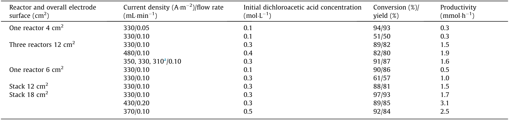
a The currents of three in series reactors were individually controlled.
《Fig. 6》

Fig. 6. Prototype of scaled electrosynthesis microreactor in laboratory and pilot-scale flow battery for reference. (a) Schematic of an eight-channel electrochemical microreactor [15]. (b) A photograph of XL 200 flow battery module stack for energy storage. (c) Single electrode compartment and side view of XL 10 reactor stack, showing the location of flanges and manifolds (not to scale). PE: polyethylene. (b, c) Reproduced from Ref. [1] with permission of Elsevier, ©2018.
《5. Summary and outlook》
5. Summary and outlook
Due to the focus on the development of environmentally responsible and sustainable chemical synthesis processes, electrosynthesis methods have been garnering interest. The combination of electrosynthesis methods and microreaction technologies has great potentials for use in chemical industry, as an important component of a flow chemistry system. The benefits of electrosynthesis microreactors include atom economy, green and safe processing, and easy scale-up, which is believed to achieve a versatile field of the area of chemistry and chemical engineering. Reducing the distance between electrodes and increasing the electrode area effectively reduce ionic transport resistance and realize controllable electrosynthesis, which addresses the shortcomings of traditional batch reactors and may propel the industrialization of electrosynthesis technology. Although electrosynthesis microreactors have many advantages, the factors governing the electrosynthesis process require elucidation since, to the best of our knowledge, the laws of flow and transport phenomena in electrode embedded microchannels are unique and research methods on electrosynthesis microreaction processes are limited. In addition to the flow patterns we have discussed, other useful flow patterns, such as organic–aqueous Taylor flow [71], may be employed in electrosynthesis processes to overcome the low electrical conductivity of organic solutions by creating phase transition processes [13]. In the field of microfluidics, it is well known that the wetting property of a microchannel strongly influences the flow pattern [72,73] which, in turn, affects the mass transfer performance [74], but the variation rules of fluid contact angle on a charged electrode are still underreported in current electrosynthesis studies. The influence of electrode interfacial properties on the electrochemical microreaction process requires careful study as well. Additionally, microscale transport experimental studies of the mass and heat transfer rates in electrosynthesis microreactors, focusing on quantification and modeling, should be established. Reaction kinetics is another important and underreported aspect of electrosynthesis reactions. Finally, most electrosynthesis reactors still use classic inert electrodes without advanced electrocatalyst materials. The combination of electrosynthesis and electrocatalysis technology has produced promising results such as using NixB-modified Ni foam (NF) to achieve the effective electro-oxidation of 5-(hydroxymethyl)furfural [75] and the hydrogenation of furfural with Pd/C cathode in a continuous flow membrane reactor [76]. Therefore, the development of material science will inform electrosynthesis microreaction technology.
《Acknowledgements》
Acknowledgements
We would like to acknowledge the supports from the National Natural Science Foundation of China (21776150) and the State Key Laboratory of Chemical Engineering (SKL-ChE-20Z01).
《Compliance with ethics guidelines》
Compliance with ethics guidelines
Siyuan Zheng, Junyu Yan, and Kai Wang declare that they have no conflict of interest or financial conflicts to disclose.


 京公网安备 11010502051620号


