

《1. Introduction》
1. Introduction
It is important to take into account the problem of gas transfer through cracks in concrete structures when evaluating the durability and safety of strategic structures such as nuclear power plant vessels. For that reason, the French Institute of Sciences and Technologies for Transportation, Development, and Networks (IFSTTAR) has implemented research linking the development of a numerical model with an experimental study to treat the problem of gas transfer through cracks in concrete. Previously, IFSTTAR undertook similar research to address the problem of liquid transfer through cracks in concrete structures [1,2]. Thus, the present research can be considered to be an adaptation or a development of the previous work, especially in regard to the experimental aspects. The same numerical model related to the concrete cracking process—that is, the semi-explicit probabilistic cracking model developed by IFSTTAR [3,4]—is used in the framework of the present research, so the model is not presented in the current paper. Adaptation of the previous work related to liquid transfer [1,2] was necessary, because it is more delicate, experimentally speaking, to pass a gas through a crack than to pass a liquid.
The experimental work presented herein was performed within the framework of the MACENA project (ANR-11-RSNR-012) managed by France’s National Research Agency. A large part of the experimental results have already been published (in French) in a report related to this project [5]. What is new in the present paper concerns the analysis of (and the physical assumptions proposed within) the experimental results. This analysis leads to the proposal of a novel relationship (which was not proposed in the report) between apparent macrocrack opening and apparent gas permeability.
The few experimental studies that are available in the literature on air flows in cracked concrete structures do not provide a reliable analysis of the main physical phenomena involved and their couplings. Most of these studies involve large reinforced concrete structural members [6–12]. Given the simultaneous presence of several localized macrocracks, an objective determination of the air flow associated with each crack is difficult. Therefore, these experimental results did not permit the identification of a flow law related to the cracking process. Therefore, in order to access this identification, experimental techniques that make it possible to generate a single crack in a small concrete specimen and to determine fluid transfer properties are more relevant. For this purpose, Ismail et al. [13] proposed a test based on the use of a toroidal measuring cell for the measurement of the permeability of a cracked hollow cylindrical specimen, while splitting tests (i.e., Brazilian tests) were used by Picandet et al. [14]. In this second case, the experimental protocol can be schematized according to the following three phases: In an initial phase, the crack is mechanically generated up to a given opening. In the second phase, the sample is unloaded and the geometry of the crack is characterized using optical instruments. Finally, in the last phase of the test, the permeability of the cracked specimen is estimated by means of a standard measurement method (the Cembureau protocol) in relation to the previously characterized crack opening. It should be emphasized, however, that the geometry of the crack can vary significantly during the permeability test because reclosing phenomena can occur for several reasons (i.e., elastic unloading of the specimen or application of radial containment pressure during the Cembureau protocol). Based on this consideration, Choinska et al. [15] discussed the possibility of real-time permeability measurements with mechanical loading. In the protocol they proposed, one side of the specimen was fitted with a covering that permitted the arrival of air, while a digital image correlation (DIC) technique was used for the real-time monitoring of the displacement field on the second side of the specimen. Some results related to this protocol were recently presented by Ezzedine El Dandachy [16]. Although that test [15,16] is similar to the one proposed in the present experimental study (see Section 2), two important points to guarantee reliable results were not discussed in detail, namely:
• Sufficient control of the macrocrack propagation and a precise determination of its opening;
• Prevention of gas leakage due to the test setup, as a gas leak introduces an error into the determination of apparent permeability.
In the present experimental work, these two points are precisely taken into account (see Section 2).
《2. Testing procedures》
2. Testing procedures
《2.1. Mechanical aspects》
2.1. Mechanical aspects
The mechanical aspects of the testing procedures presented herein involve the creation of a single crack with an increasingly controlled and measured opening. This mechanical step is unchanged from that of the previous experimental study [1,2], in which a liquid was passed through a crack. The mechanical step can be summarized as following:
Step 1. A splitting test (Brazilian test) was performed on a concrete disc (110 mm in diameter and 50 mm thick). This test was carried out on a Tinus Olssen (± 500 kN) hydraulic press equipped with a closed-loop control system.
Step 2. Steering of the press was adapted to control the crack opening and to obtain a single crack centered on the faces of the specimen [17].
Step 3. The crack opening was controlled by measuring the diameter variations of the specimen perpendicular to the crack. This measurement was made 15 mm behind the median plane and 15 mm before it (by using Linear Variable Differential Transformers (LVDT) of ±1 mm for ±10 V), as indicated in Fig. 1 [5]. The average of these pieces of data was calculated in real time in order to better control the test. This step prevents a loss of control when the snap-back phenomenon occurs [18].
《Fig. 1》
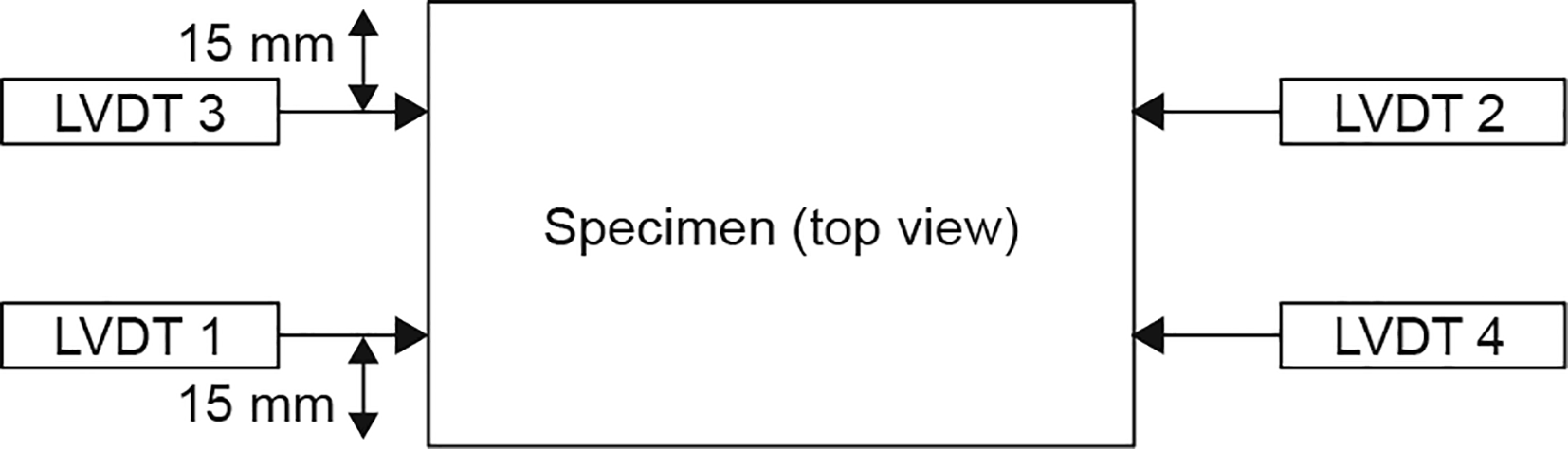
Fig. 1. Schematic diagram of the measurement of diametric expansions of the test specimen.
Step 4. The measurement of the diametric expansion of the specimen was connected to the crack opening measurement. For this purpose, and very schematically, the following strategy was developed:
• The measurement of LVDTs made it possible to estimate the diametrical expansion of the test specimen to the right of the faces of the specimen. By removing the elastic part of the deformations (i.e., linear law, function of the force, determined in the first elastic loading) from this diametric expansion estimation, an estimation of the crack opening at the-mid-heigh of the specimen and for each of the faces was obtained.
• In comparison, the previous experimental study [1,2] used DIC techniques to develop a linear statistical relationship between the mean effective surface area and the average opening crack in the center of the crack. A comparison was performed between the crack opening at the mid-height of the specimen obtained by using the DIC technique analysis with the same data obtained by using LVDT measurements. For all tested specimens, this comparison yielded a repeatable and consistent result.
Concerning the crack opening determination with the proposed mechanical test setup, a few comments can be made:
Comment 1. The maximum crack openings did not appear at the mid-height of the specimen (along the crack). This was the case for the majority of specimens tested. This observation is easily explained by the very heterogeneous character of the concrete.
Comment 2. It has been demonstrated in the past—through both observation and explanation—that, during crack propagation in a concrete structure, the crack propagates faster at the surface than inside [19,20]. Moreover, inside the cracked structure, there are several ‘‘material bridges” that result in discontinuous crack propagation. This difference between the surface and inside cracking means that the surface crack is not representative of the global reality of the crack. This is the reason why it is common to refer to the apparent crack opening when discussing the average crack opening at the specimen center.
Comment 3. The measurement of the crack opening obtained using LVDT measurements appears to be a more global measurement than the one using the DIC technique.
As a result, the following assumptions are made in the framework of the present study:
Assumption 1. The crack is considered to be two plane surfaces separated by the same distance along the entire length of the crack.
Assumption 2. The distance between the two planar surfaces is given by the measurement of the crack opening at mid-height of the specimen, which is considered to be the average of the crack openings along the crack.
This choice is considered to be acceptable, even though strong assumptions have been made. It is very different from the choice proposed in Ref. [5] that served as a basis for the present work; in fact, in the previous report, the crack opening was calculated as the average crack opening along the crack surfaces (using DIC analysis) [1,2,5].
《2.2. Hydraulic aspects》
2.2. Hydraulic aspects
The hydraulic aspects make up the more important and difficult part of this experimental study.
During the previous study, which focused on water transfer through a crack [2], the portion of the face of the specimen that was subjected to water loading was not the total surface of the specimen; rather, it was a reduced area due to the presence of tanks and joints on the two specimen faces. Therefore, during the liquid permeability test, the surface exposed to hydraulic pressure was limited to a circular surface with a diameter (called the effective diameter) equal to the internal diameter of the silicone joints, at 77 mm. Similarly, only a portion of the surface of the crack was considered to be representative of the percolation area of the liquid.
The same general setup was used in the present study (Fig. 2 [5]).
《Fig. 2》
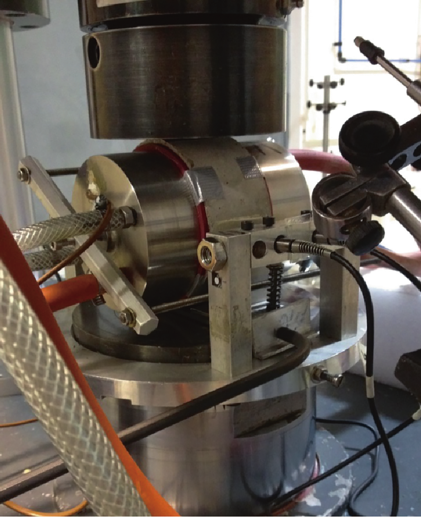
Fig. 2. Photo of the experimental set-up.
However, as the present study concerned gas transfer rather liquid transfer, there were some difficulties to overcome. The main difficulty concerned the problem of potential gas leaks, which will be discussed further below. For the permeability tests, the device comprised two steel tanks, which were placed on the faces of the specimen and tightened by means of a screw system.
The upstream pressure chamber was connected to a pressurized, regulated, filtered air circuit, while the downstream chamber was connected to a vacuum pump [5]. A pressure regulator and a mass flow meter with a thermal effect (Bronkhorst®, F-111AC50K-AAD-33V, 1–50 nL·min–1 , Bronkhorst High-Tech B.V., the Netherlands) were positioned upstream of the device. The vacuum pump was positioned downstream, and permitted a minimum pressure of 30 mbars (3 kPa). Thermocouples were used to measure the fluid temperatures in the chambers. Two silicone joints (2 mm thick) were interposed between the tanks and the faces of the specimen to prevent air leakage on the upstream and downstream faces. Their low rigidity ensured that no mechanical action of confinement, associated with the presence of the chamber bodies, was exerted on the specimen. The air inlet in the upstream chamber was cooled by means of a coil immersed in a thermostated bath and maintained at a temperature of 22 °C.
The following measurements were made: the four LVDTs of diametric expansion measurement, cylinder displacement, date and time, upstream pressure, downstream pressure, differential pressure between the two chambers, mass flow, upstream and downstream temperatures, and the force applied on the specimen. The main deficiencies of the experimental mode in comparison with the experimental study on water permeability [1,2,5] were as follows: ① The use of a mass flow meter(s) adapted to air transfer and the flows measured; ② the use of a pressure regulator; ③ the use of a vacuum pump; and ④ the manufacture of a cooling coil for the air supply circuit to ensure that the gas remained at a constant temperature so the flow was considered isothermal (which is still a strong assumption).
The first tests that were realized with this test setup showed that there was an gas leak despite the presence of the silicone joints. The following steps were taken to solve this problem: ① ABM75 was used on the cylindrical periphery of the specimen. This product is usually used to glue strain gages on concrete specimens. ② An additional mass flow meter (with the same characteristics as the first one) was used to verify the efficiency of this new solution.
Fig. 3 presents a comparison between the upstream and downstream air flow rates given by the two mass flow meters, which can be considered to be substantially identical during the test [5]. The perturbation of the downstream flow measurement was related to the technology of the vacuum pump (a diaphragm pump) and to the fact that it must constantly draw air to reach the set point, when the crack opening is somewhat important. When the pump was temporarily stopped, the values were much more stable.
《Fig. 3》
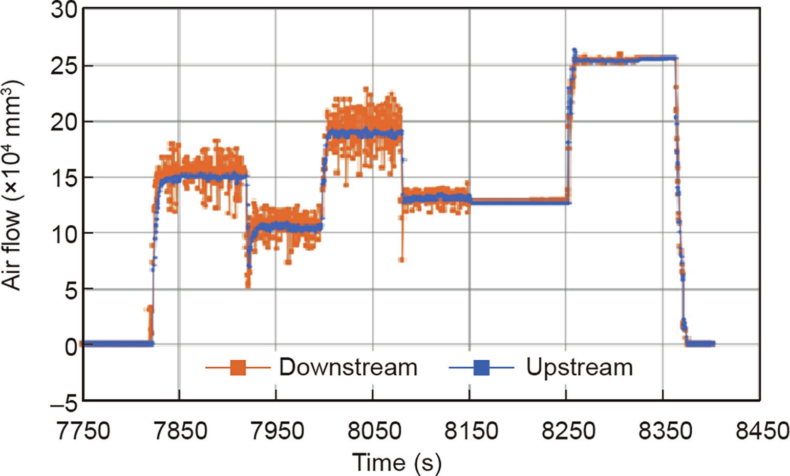
Fig. 3. A comparison of the upstream and downstream flows during a cracking state.
《3. Testing program》
3. Testing program
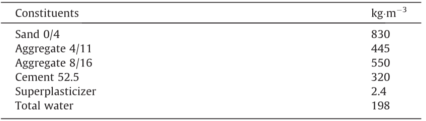
The concrete mix design used during this study is given in Table 1.
《Table 1》
Table 1 Mix design of the studied concrete.
The specimens were stored under endogenous conditions, protected by two layers of self-adhesive aluminium on a layer of cellophane film. This protection was maintained until the tests began. The aluminium shield was removed from the faces of the specimen for permeability testing but was left on the cylindrical periphery. The mechanical load was transmitted through this thin protection. This arrangement resulted in a better distribution of this load than that obtained with the conventional plywood typically used in standardized splitting tests. The tests carried out during this experimental campaign were subject to relatively low specific pressure conditions in order to minimize the effect of the compressibility of the fluid. The pressure ratios (calculated between the upstream and downstream pressures) that were imposed were 1.2 and 1.5. These pressure ratios can be considered low compared with those in standardized permeability tests. This choice was governed by two aspects: ① To avoid having to consider the compressibility of the gas, which could generate difficulties in the analysis of the experimental results; and ② To avoid gas leakage. Indeed, during the first tests performed with the proposed test setup, some gas leakage was observed when higher pressure ratios were imposed.
Fig. 4 shows an example of the cycle of pressure conditions imposed during a cracking process [5]. As shown in the figure, the maximum downstream pressure imposed during the test (obtained by using a vacuum pump) was slightly greater than 1 bar (100 kPa), which corresponds to the average atmospheric pressure.
《Fig. 4》
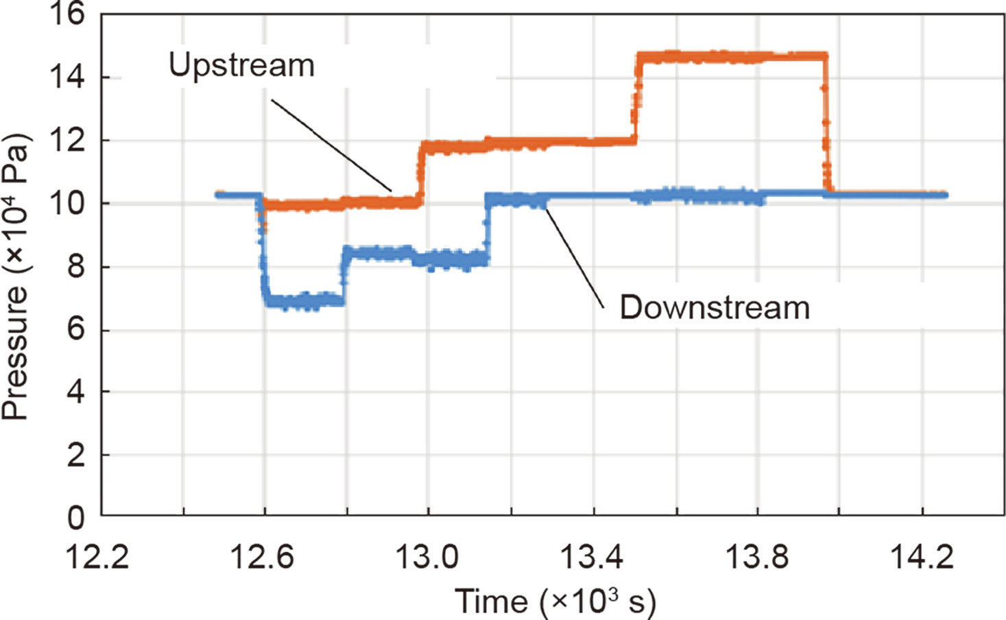
Fig. 4. An example of the upstream and downstream pressure conditions imposed during a cracking process.
Crack openings were regularly imposed during the tests. As the test was controlled indirectly (as a function of the diametric expansion and the imposed force), the applied force was not constant, although it varied very little. The imposed crack openings are presented in Fig. 5 [5]. Four specimens were successfully tested during this study.
《Fig. 5》

Fig. 5. Imposed crack openings during the test. Reproduced from Ref. [5].
《4. Results and analysis》
4. Results and analysis
Schematically, the movement of gas in the crack can be approximated by to the flow of fluid between two flat plates. The following assumptions were made in the framework of this study: a perfect gas, an established flow, a low-pressure ratio, and constant volume flow. All these assumptions make it possible to write the conservation of the integrated momentum related to the volume of the crack in the form of a relationship between the macroscopic pressure gradient squared  and a function of the mass flow (q), where p1 is the upstream pressure and p2 is the downstream pressure. This relation (in theory and taking into account the assumptions framework) must to be linear and have the following form:

where r, T, w, μ, ρm, and S respectively designate the specific constant of the perfect gases, temperature, distance between the flow planes, dynamic viscosity, density, and flow section.

Remark: Eq. (1) is very close, in its formalism, to that of Poiseuille’ law.
Fig. 6 shows curves related to the pressure gradient squared versus the mass flow for a few crack openings. This figure comes from Ref. [5] with an important change, which is the way in which crack openings are determined (see Section 2). It can be noted that these curves show small nonlinearity, especially for a larger mass flow. This observation contradicts the theoretical relationship obtained in the framework of the assumptions that were made. This apparent contradiction can be explained by the presence of material bridges inside the cracked part of the specimen. The greater the mass flow and the squared pressure gradient are, the greater the quantity of air that penetrates inside these material bridges will be. It is this increasing quantity of air trapped in the material bridges (and the quantity of air passing through the non-cracked concrete via the crack surfaces), that could lead to the observed nonlinearity of the curves.
《Fig. 6》
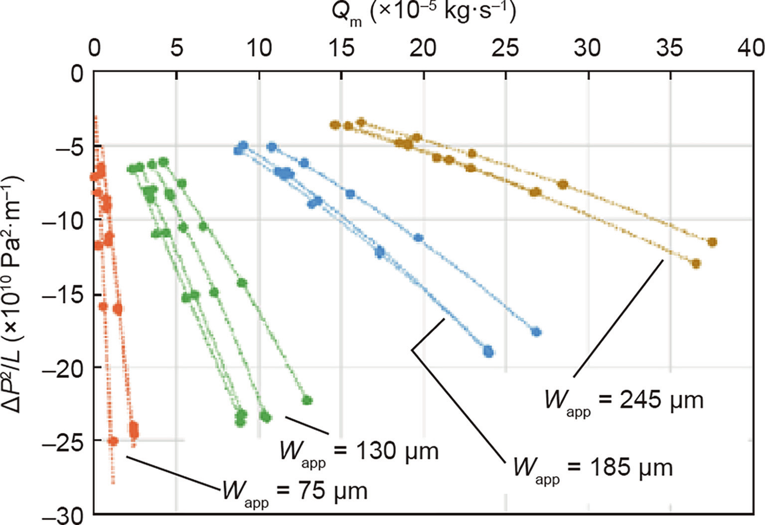
Fig. 6. Squared pressure gradient curves vs. mass flow (Qm) for different values of apparent crack openings and different specimens.
As shown in Fig. 6, the linear parts of the curves were used to determine the apparent permeability of the crack according to its apparent opening (using Eq. (1)).
Fig. 7 presents the curve related to apparent crack permeability (Kapp) versus apparent crack opening (Wapp). This figure also depicts the curve that would expected based on the strict application of theory.
《Fig. 7》

Fig. 7. Apparent permeability vs apparent crack opening curve: An exact fitting curve of the experimental points.
It is observed that:
• The shape of the curve relative to the cracked concrete specimen is similar to the theoretical curve (a power function).
• The apparent crack permeability of the cracked concrete is less than what occurs in the presence of a theoretical crack, which is an expected result. This difference becomes smaller when the crack opening becomes larger (for crack openings larger than 200 microns).
It is possible to fit the curve of Fig. 7 with an analytical relation (Eq. (3)):

It is obvious that Eq. (3) depends on the concrete under consideration and, in particular, on its level of heterogeneity and porosity. Thus, it should be interesting to perform the same type of experimental study on other types of concrete to obtain more general information. It is also important to reiterate the fact that Eq. (3) must be considered an approximation of reality, due to the fact that the crack opening and the distance of the air transfer considered in this study are roughly evaluated.
For these reasons, it is acceptable to approximate the value 2.8569 of Eq. (3) as 2.8 or 2.9. Fig. 8 shows that these two values are relevant to fit the experimental points.
《Fig. 8》
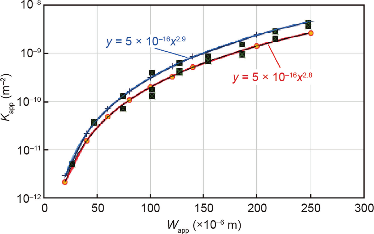
Fig. 8. Apparent permeability vs apparent crack opening curves: Two approximate fitting curves.
Another point to focus on is the fact that the proposed test protocol results in the imposition of some (but not all) downstream pressures that are lower than the atmospheric pressure (Fig. 4). However, in a real situation related to a nuclear power plant vessel, this downstream pressure is never lower than the atmospheric pressure. It can be argued that, if this situation had a significant influence on the analysis of the experimental results, Fig. 7 would be much more disturbed than it is.
Finally, it is important to note that Eq. (3) can be considered to be currently valid with regard to the values of the pressure and pressure ratios considered in this study. Another test setup and test protocol would have to be developed to study higher pressures and pressure ratios in order to perform a more comprehensive analysis.
《5. Discussion and conclusions》
5. Discussion and conclusions
This paper performs an analysis on an experimental study that aimed to determine the apparent gas permeability of a crack in concrete. To achieve this objective, the test setup included the following: ① A splitting test was conducted on a concrete disc 110 mm in diameter and 50 mm thick to generate the crack. ② Control and measurement of the crack opening at the center of the specimen was performed. ③ A gas permeability test was conducted using a device comprising two steel tanks placed on the faces of the specimen and tightened by means of a screw system. The upstream pressure chamber was connected to a pressurized, regulated, and filtered air circuit. The downstream chamber was connected to a vacuum pump.
The following principal results were obtained:
• The mechanical procedure added makes it possible to control crack creation well and to measure the average crack opening at the specimen center.
• The hydraulic procedure demonstrated that the macroscopic pressure gradient was well imposed and measured, and there were no gas leaks in the system.
• The evolution of the apparent gas permeability as a function of the apparent crack opening is relevant based on Poiseuille theory.
It is important to point out that the experimental approach (and the analysis of it) proposed for determining the evolution of the apparent gas permeability as a function of a macrocrack opening must be viewed as an engineering approach leading to macroscopic information. The use of this information in the context of a numerical model is reasonable and may be considered relevant only if this model is also macroscopic and is used as an engineering tool.
From a more physical point of view, this approach is open to criticism because it is based on a very strong assumption that there is the existence of a known and constant pressure gradient within the crack. However, due to the great difference in volume between the tanks and the crack, this assumption is not obvious. If the maximal macrocrack opening during the test is less than 0.3 mm, the ratio of the crack opening to the diameter of the specimen (110 mm) and thus to the diameter of the tanks of gas under pressure is greater than 3/1000. Therefore, it is not unreasonable to consider the contact surface between the gas and the crack to be infinite. If this assumption of infinity is accepted as relevant, it is also reasonable to accept that the experimental test realizes a sufficient simulation of what occurs in a real nuclear power vessel. Under these conditions, even if the real pressure gradient existing between the entrance and the exit of the macrocrack is not well determined, it can be considered that the apparent permeability obtained during the test is acceptable within the framework of this study’s domain of application.
In conclusion, it can be argued that, in order to realize a more relevant theoretical approach, it should be necessary to change the modeling scales for the cracking and the fluid transfer, and to develop other types of test setup. Finally, it should be remembered that the aim of the experimental study (and its analysis) presented in this paper is to provide useful information about leaks through a macrocracked nuclear power plant vessel when the external (atmospheric pressure) and internal (in case of accident) pressures are known or predictable but the pressures at the entry and exit of the macrocracks are not.
《Acknowledgments》
Acknowledgments
The authors gratefully acknowledge funding support from French National Research Agency through the MACENA project (ANR-11-RSNR-012).


 京公网安备 11010502051620号


