
《1. Historical context》
1. Historical context
Flow in porous media is encountered in a wide variety of natural and engineered settings, including gas exchange in lungs and blood vessels, water extraction from underground aquifers, hydrocarbon production, and microfluidics in drug delivery and food manufacturing. Underground rock is a porous medium that holds water and hydrocarbons, and is a potential storage site for carbon dioxide (CO2) and hydrogen. Many manufactured devices also contain porous media to allow the transport of gases and water, including fuel cells, electrolyzers, and electrocatalysts for CO2 reduction. Their performance is limited by how rapidly two fluid phases can flow through a porous layer.
However, until recently, almost all the research and systematic studies in this field were concentrated on geological systems—that is, soils and rocks. Flow in porous media was first quantified using Darcy’s law in 1856 to describe the movement of water in sand filters [1]. Subsequently, it was employed to study groundwater flow in hydrology [2]. Later, starting with the pioneering work of Muskat and Meres [3] and Wyckoff et al. [4] in the 1930s. Darcy’s law was used to estimate permeability based on measurements of flow and pressure gradient in small rock samples taken from oil reservoirs; the unit of permeability, named after Darcy, was also defined [4]. In addition, the flow of more than one fluid phase was quantified through the introduction of saturation-dependent relative permeability [3] and capillary pressure functions [5]. For the last 90 years, the flow properties of rock samples have been estimated by the oil industry for kilometer-scale assessments in order to predict and design oil-recovery strategies. In hydrology, the development of the theory of flow in porous media and its extension to multiphase flow was pursued largely independently, with a focus on water movement only [6].
Over the last 50 years, a number of factors have led to the establishment of flow in porous media as a scientific discipline in its own right, unshackled from application-specific constraints and silos. Several events promoted this shift. The first was the publication of Jacob Bear’s seminal work Dynamics of Fluids in Porous Media [7] in 1972, which laid the foundation for a rigorous treatment of flow and transport in porous media. Next was the realization by the hydrology community in the 1980s that pollutants could reside within their own phase, and that an understanding of their flow could be borrowed from decades of previous work in the oil industry. This exchange of ideas was facilitated by conferences and journals in which the two communities of hydrology and petroleum presented and published together; examples include the Gordon Conference of Flow and Transport in Permeable Media, which runs every other year, and the foundation (again by Jacob Bear) of the journal Transport in Porous Media in 1986.
Further impetus for this field came from studies of CO2 storage as a climate change mitigation strategy, from the 1990s onwards. In this context, it was natural for the petroleum and hydrology communities to work together on a common problem: designing the injection of CO2 into the subsurface, given that the long-term fate of the injected CO2 requires a knowledge of multiphase flow in porous media [8]. Again, however, the focus of application concentrated on flow in rocks deep underground.
The movement toward a discipline that encompassed all porous systems, not just rocks, within a common scientific framework was encouraged by the establishment of the Interpore Society in 2008, with the explicit goal of bringing together researchers interested in all types of porous material. Significant effort has been devoted to presenting a wide range of topics involving non-geological porous materials at presentations and conferences.
These developments have not been pursued through organizational efforts alone; there have also been transformative enhancements in experimental, analysis, and computational techniques, including the advent of three-dimensional (3D) imaging using X-rays, magnetic resonance imaging (MRI), and electron microscopy [9]. It is now possible to look inside opaque porous materials to observe the pore space with nanometer to millimeter resolution, and to observe the fluids within the pore space and their displacement. This development has been coupled with advanced computational methods that can simulate fluid flow, thereby solving the Navier–Stokes and Young–Laplace equations at a small scale, from which averaged macroscopic properties can be computed.
As described above, research on flow in porous media was hitherto concentrated on geological media, with the principal application being improved oil and gas production. As the world deals with the threat of dangerous climate change and the need to move toward net zero emissions of CO2 and therefore to reduce fossil fuel extraction, it may appear that flow in porous media has a less significant role to play. However, the same science can be used to understand a variety of processes that are vital to the energy transition and to carbon neutrality.
《2. Carbon dioxide storage and electrochemical devices》
2. Carbon dioxide storage and electrochemical devices
The first application of flow in porous media that is relevant to the energy transition, as mentioned above, is in developing a better understanding of subsurface CO2 storage. Here, a combination of imaging and modeling at multiple scales has been used to study the fate of CO2 injected into a porous medium. It is now well established that injected CO2 can be safely stored under appropriate conditions, retained in the pore space by a series of trapping mechanisms. These include structural trapping below low-permeability cap rock, capillary trapping in pore-sized ganglia surrounded by water, dissolution, and reaction [10].
Moreover, the applications of this concept are broader than flow in rocks. Electrochemical devices are an essential component of a zero-carbon energy system. They are ubiquitous in modern life and are set to become increasingly important as we move toward a renewable-based low-carbon economy. Examples of devices that have been studied using high-resolution imaging and modeling include: batteries [11]; fuel cells, in which a fuel is reacted with oxygen, producing a current [12–14]; and electrolyzers, which work in reverse to use a current to produce a fuel (e.g., hydrogen) [15]. It is not desirable for phases to be trapped; instead, for fuel cell and electrolyzer applications, gas and water need to flow through a porous layer (called the gas diffusion layer in a fuel cell) in as unimpeded a manner as possible. More specifically, in a hydrogen fuel cell, oxygen reacts with hydrogen to produce water; the power of the device is related to how quickly oxygen can flow to the reactive catalyst layer and how rapidly the produced water can escape. This problem is akin to oil recovery. We want two phases (a gas and water, in this example) to flow readily over a wide saturation range. In a battery, liquid electrolyte is introduced into a dry solid framework under a vacuum. However, it is possible for pockets of vapor to be trapped, which reduces the efficiency and lifetime of the device [16]. We know that flow and trapping are controlled by pore structure and wettability, the latter of which is defined as the interaction of fluid phases with a solid phase, quantified through the distribution of contact angle [17].
Before continuing, let us return to more traditional applications and the use of new concepts. The current focus on oil-recovery applications suffers from two scientific challenges, which have impeded the widespread adoption of imaging, analysis, and modeling technologies. The first challenge is that the scale of investigation—which ranges from microns to millimeters—is many orders of magnitude smaller that the size of the reservoirs being studied, which are several kilometers in extent. Hence, while it is possible to obtain valuable insights into local displacement processes by these means, it is also necessary to know the larger scale structure of the reservoir in order to quantify flow processes. Second, although it is possible to assess local recovery, opportunities to change the fluid–rock interaction in order to improve it are limited, since this involves expensive investment in the injection of different fluids or chemicals. Due to uncertainties in predicting the larger scale flow and the difficulty of manipulating injected materials, this technology often simply provides properties for use in larger scale simulations.
In contrast, both of these problems are insignificant in the study of manufactured devices. Here, the size of the sample being imaged is often the same as that of the sample within the device itself, or close to it. Furthermore, for a manufactured material, the aim is not simply to quantify performance, but also to design the pore space and fluids in order to optimize performance. Hence, the opportunities for this new technology to be transformative are much greater in manufactured devices than in traditional subsurface flow applications.
《3. Flow and trapping》
3. Flow and trapping
We will now focus on two processes in multiphase displacement: flow and trapping. For CO2 storage, it is desirable for the injected CO2 to be trapped in the pore space as quickly and effectively as possible, in order to prevent its potential escape back into the atmosphere. In contrast, in electrochemical devices, the idea is to allow the flow of two phases over a wide saturation range without trapping.
Capillary trapping occurs principally through a process called snap-off, in which the wetting phase (generally water) flows in the corners and roughness of the pore space. As the saturation increases, these wetting layers swell until they touch and fill the narrowest regions of the pore space, isolating the non-wetting phase within the larger pores [18]. Fig. 1 illustrates this situation for CO2 storage applications [19]. Capillary trapping is favored when there is a large difference in size between the narrow and wide regions of the pore space. The other principal factor is wettability: Snap-off is favored for a phase that strongly wets the surface. This is illustrated in Fig. 1, in which more CO2 trapping can be observed in a depleted oilfield, where the oil forms a spreading layer between the water and CO2, with an effective gas (CO2)–oil contact angle of zero. In contrast, if CO2 is injected into an aquifer, where there is no oil present, the gas–water contact angle is larger and less trapping occurs [19].
《Fig. 1》
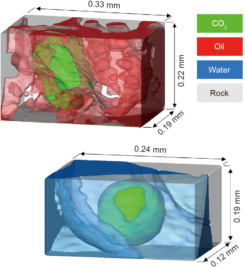
Fig. 1. 3D X-ray images of oil, water, and CO2 in the pore space of limestone. The top figure shows CO2 trapped by oil that spreads as a layer between the CO2 and water in the pore space; the oil is strongly wetting to CO2, which maximizes the degree of trapping. In the lower figure, no oil is present, and the CO2 is trapped by water. Water is the wetting phase, but it is less strongly wetting than in the presence of oil and water in the figure above; furthermore, the amount of trapping, which is quantified by the minimum saturation of CO2 at the end of a displacement process, is lower. Source: Ref. [19].
What conditions minimize trapping and encourage flow? An obvious first assumption would be conditions that are opposite to those that encourage trapping. Unlike consolidated rocks in which wider pore spaces are connected by narrow restrictions, the porous material in electrochemical devices is a fibrous layer of high porosity with relatively little variation in pore size. What about wettability? The opposite condition would be to reverse the wettability order, such that the strongly wetting phase is continuous in the corners of the pore space and, indeed, can flow at a very low saturation. However, the wetting phase is retained by capillary forces and flows slowly; hence, it cannot easily be removed. In the context of oil recovery, it is known that some intermediate wettability leads to the most favorable recovery [20]. However, the exact nature of the wetting state has been unclear until recently.
《4. Scientific hypothesis》
4. Scientific hypothesis
Our hypothesis to determine ideal flow conditions uses a theorem from topology. Consider a smooth surface bounding a 3D object: This will be a fluid–fluid (gas–water) interface bounding, say, a gas-saturated region of the pore space. At any point on a surface, we can define two principal curvatures in orthogonal directions, κ1 and κ2, with the corresponding radii R1 and R2, respectively. If we consider a sphere with radius R, these two radii are equal: R1 = R2 = R; for a cylinder with radius R, R1 = R, while R2 =  . If the surface is saddle or pear shaped, then one of the radii of curvature is negative.
The capillary pressure, Pc, can be found from the curvature using the Young–Laplace equation:

where σ is the surface tension coefficient. The Gauss–Bonnet theorem states [21]

where S is the area of the surface.
The Gaussian curvature, κG = κ1κ2, which appears in Eq. (2), is the product of the two principal curvatures: κG = 1/R2 for a sphere, κG = 0 for a cylinder, and κG < 0 for a saddle. The other term in Eq. (2) is the Euler characteristic, χ, which is a measure of the topology of an object: In this context, it is the number of objects plus the number of holes in the structure minus the number of loops. Thus, Eq. (2) relates the integral of the Gaussian curvature of an object to its topology.
For example, a solid sphere has an Euler characteristic of 1 (i.e., it has no holes or loops). The surface area of a sphere with radius R is 4πR2 : The integral of the Gaussian curvature (which is constant) over this surface is 4π, in agreement with Eq. (2). In general, though, Eq. (2) is a remarkable result, as it states that however much we distort a sphere (or, indeed, any object), so long as no holes or loops are created, the integral of the Gaussian curvature over the surface remains constant.
If a phase is trapped, it is broken up into many ganglia in the pore space and is poorly connected, which implies a large positive Euler number and, hence, on average, a large and positive Gaussian curvature. The non-wetting phase bulges out into the wetting phase with a positive curvature in both directions. For a ballshaped object, the two curvatures are of the same magnitude and sign.
Therefore, the opposite situation—that is, to encourage flow— would involve a well-connected phase, with a large negative Euler characteristic and Gaussian curvature. The gas may bulge into the water in one direction, for example, while the curvature is equal and opposite in the other direction (e.g., a pear or saddle shape) and the water bulges into the gas. Such surfaces with a zero total curvature are called minimal surfaces, and have been a source of mathematical fascination for centuries [22]. Minimal surfaces can be seen in rocks in which contact between the solid surface and crude oil has altered the wettability to make these surfaces oilwet, while other regions, particularly where water accumulates in the roughness and corners of the pore space, remain waterwet [23]. In this case, the curvature between the oil and water is close to zero, which implies a capillary pressure of almost zero, according to Eq. (1), but the oil–water menisci are not flat; instead, the interface has distinct curvatures of equal magnitude but opposite sign in orthogonal directions, as illustrated in Fig. 2 [23]. The flow properties of the fluids, quantified by the relative permeabilities, imply good recovery: Oil and water can flow through the pore space over a wide saturation range [23]. The porous medium is considered to be mixed-wet, with a combination of water-wet and oil-wet surfaces.
《Fig. 2》

Fig. 2. Oil–water menisci obtained from X-ray imaging of sandstone when water displaces oil from the pore space. On the left is a water-wet rock, in which the oil– water interfaces are ball-shaped, with a positive curvature in both directions. The capillary pressure is large and positive, and the oil can become trapped. In contrast, the figure on the right shows the interfaces in a mixed-wet rock, in which parts of the solid surface have become oil-wet after prolonged contact with crude oil. Here, there are approximately minimal surfaces, with zero capillary pressure and curvatures of opposite signs in different directions: In one way, the oil bulges into the water, while in the orthogonal direction, the water bulges into the oil. We suggest that porous materials could be designed to create minimal surfaces for the optimal, simultaneous flow of two fluid phases in a pore space. Source: Ref. [23].
Minimal surfaces are observed when the three-phase contacts between two fluid phases and a solid are pinned—that is, do not move—while the surface area between the fluid phases is minimized [22]. In rocks, three-phase contacts between water-wet and altered-wettability regions are indeed pinned in many cases; however, these cannot be exactly minimal surfaces, as some contacts must move to allow fluid displacement.
The hypothesis is as follows: To encourage flow, a mixed-wet state is ideal, such that both the gaseous and water phases can flow and displace each other with as low a capillary pressure (i.e., pressure difference between the phases) as possible. Empirically, this is achieved in fuel cells, where the naturally water-wet carbon fibers are coated with polytetrafluoroethylene (PTFE) to render the surfaces oil-wet (or hydrophobic, in that water is non-wetting to gas). There is a mix of hydrophilic (water-wet) and hydrophobic regions in the gas diffusion layer. This concept is illustrated in Fig. 3, where high-resolution X-ray imaging has been applied to the fibrous material to image water in the pore space in a gas diffusion layer [24]. However, no systematic study has examined the relation among wettability, curvature, and device performance. We suggest using X-ray imaging to quantify the wetting state, and then designing the proportion and arrangement of coated fibers to minimize the capillary pressure. Other researchers have instead suggested that the porous layer should have alternating patches of channels of hydrophilic and hydrophobic material [15,25], or have constructed an ordered anisotropic material in which the water flows in distinct channels [26].
《Fig. 3》

Fig. 3. X-ray images of water in a gas diffusion layer. Grey represents the gas diffusion layer, red represents the water before breakthrough, and blue is the water droplet formed after breakthrough. We hypothesize that an ideal performance that allows the rapid flow of both gases and water occurs when the fluid menisci have approximately zero curvature, and hence are minimal surfaces. Source: Ref. [24].
Another important consideration is the quantification of uncertainty, both in the measurements themselves, such as the contact angle, and in the porous media studied, since individual samples have different microstructures. The application of methods developed for subsurface flow in order to quantify uncertainty and apply inverse techniques to derive flow properties from the observed displacement process is a rich area of investigation [27].
The final problem is the full saturation of batteries by electrolyte. Here, the key feature is that the pore space is originally dry, in that the wetting phase is not already present in the smaller regions of the pore space. Without flow in wetting layers, snap-off cannot occur. Instead, there is a flat frontal advance of the wetting phase with little trapping [18]. This advance is encouraged by strongly wetting conditions (assuming no layer flow); hence, the electrolyte and solid substrate should be designed so that the electrolyte strongly wets the surface.
《5. Conclusions and implications》
5. Conclusions and implications
In this short discussion, we have suggested applications of multiphase flow in porous media that are relevant to the current energy transition. While the study of CO2 storage is well established and uses concepts borrowed from hydrology and petroleum engineering, the application of ideas that are relevant to understanding flow processes in electrochemical devices is more recent.
We have proposed a framework for designing multiphase displacement that is optimal for flow, trapping, and saturation. This framework can be used to design efficient devices and effective storage schemes that make use of recent advances in non-destructive 3D imaging, analysis, and modeling. To be specific, we suggest that mixed-wet porous materials in which the fluid–fluid menisci have approximately minimal surfaces with no overall curvature are ideal for allowing two phases to flow through the pore space over a wide saturation range. More broadly, the use of modern methods in imaging, analysis, and modeling, briefly reviewed here, is likely to have a significant impact on the design of a wide range of porous media processes, from medicine to food processing and catalysis, among others.


 京公网安备 11010502051620号


