

《1. Introduction》
1. Introduction
The wide application of monolithic inorganic non-metallic materials is limited by their inferior electrical conductivity [1,2]. Conductive fillers such as carbonaceous materials [3–5], metallic materials [6–8], and conductive polymers [9,10] have been introduced into non-metallic materials to improve their electrical properties. When the fraction of conductive fillers reaches the percolation threshold, conductive networks become connected, resulting in the formation of electrically conductive composites [11–13]. The obtained conductive composites exhibit low density, high thermal stability, excellent chemical inertness, and reliable mechanical properties, allowing them to be used in various applications [14,15].
In general, conductive materials inside inorganic non-metallic composites can generate heat under applied voltages; hence, they can be used in various applications, including deicing, defogging, indoor climate control, and thermal therapy [16–18]. Electrons transfer energy to the atoms of the conductor via inelastic collisions, and the electric current is converted into heat [19–21]. Carbonaceous materials have been widely used as exceptional nanoscale fillers (e.g., graphene, graphite, carbon nanotubes, and carbon fibers) for constructing conductive composites owing to their outstanding electrical conductivity, excellent chemical inertness, and high thermal conductivity [22–24]. Several previous studies have reported carbon fiber filament/fabric-based cement composites [25,26]; however, in these composites, heat can be generated only above the heating element on a limited heat distribution area [27]. Additionally, researchers have reported the fabrication of conductive ceramic composites (CCCs) by integrating conductive fillers into sol–gel precursors [28,29]. It was suggested that the concentrated sol–gel improved the interface, mechanical properties, and electromagnetic interference (EMI) shielding of the ceramic composites even under extreme conditions, which renders the composites suitable for use in aerospace and military fields [30–33]. The surplus mechanical performance, complex preparation process, and high production costs limit their application in daily life. Therefore, researchers are currently attempting to establish a facile and scalable method to fabricate CCCs that afford electro-thermal performance, as well as to clarify the mechanism that affects the electro-thermal conversion performance and efficiency.
Triaxial ceramics are one of the most widely used ceramics; they can be used for various applications, including tiles, stoneware, and whiteware [34,35]. Their production requires only uniaxial pressing (dry pressing) ceramic precursor powders (kaolin, quartz, and feldspar) in a mold, followed by sintering at a high temperature [36]. The easy access to raw materials and simple production process renders them a promising candidate for achieving a scalable production of CCCs [37]. It is noteworthy that the sintering temperature of triaxial ceramics is in the same range as the carbonization temperatures of most carbonaceous materials [38–40]. In our previous study, a simple single-step firing method was used to fabricate carbonized fibers/ceramics based on an industrial drypressing method. The carbonization of different types of precursor fibers (polymer [41], cellulose [42], and protein [43]) and the ceramization of triaxial ceramics were achieved in a single firing process. This method significantly reduces the production time and energy input required for the fabrication of carbon fiber/ceramic composites. However, the inferior interface between the fiber and ceramic matrix caused by fiber shrinkage and uneven heat distribution must be addressed to obtain the optimal CCCs.
Herein, we report the scalable fabrication of a CCC based on a phenolic resin solution using a dry-pressing method. The controllable viscosity of the phenolic resin facilitates its homogeneous dispersion in the green body after dry pressing [44]. High electrical conductivity is generated from the carbonization of phenolic resin, which endows the obtained composites with excellent electrothermal performance and low energy consumption for electric heating. The effect of the phenolic resin content on both the electro-thermal performance and power density was investigated comprehensively. An even heat distribution was observed on the composite surface under a specific voltage. Furthermore, the composites demonstrated a distinct EMI shielding performance compared with that of the pristine ceramic. The excellent electrical properties and easy fabrication, among others, of the obtained composite render it a potential candidate for diverse applications, such as indoor climate control, deicing, cooking, and EMI shielding.
《2. Materials and methods》
2. Materials and methods
《2.1. Materials》
2.1. Materials
Triaxial ceramic precursors with an average size of 20.5 μm were purchased from Houson Building Materials Co., Ltd., China. The main components of the mixed ceramic precursors were kaolin, quartz, and feldspar. The corresponding chemical compositions are listed in Table 1, and the particle-size distributions are shown in Fig. S1 in Appendix A. Phenol resin, polyvinyl butyral (PVB), and ethanol were purchased from Shanghai Aladdin Biochemical Technology Co., Ltd., China. All materials were used without further purification.
《Table 1》
Table 1 Chemical compositions of the mixed ceramic precursors.

《2.2. Preparation of CCCs》
2.2. Preparation of CCCs
Phenol resin solutions at different concentrations (10, 15, 20, 25, and 30 wt%) were prepared by mixing phenol and PVB (0.6 wt%) in ethanol via magnetic stirring for 6 h at room temperature. Subsequently, 10 g of ceramic precursor powder was mixed with 2 mL of phenol resin solution at different concentrations in a steel die (50 mm × 20 mm) to prepare the ceramic green body. Briefly, 4 g of ceramic precursor powder was placed into the bottom of the die; subsequently, 1 mL of phenol resin solution was sprayed on the surface of the powder homogeneously. Next, 3 g of ceramic precursor powder and 1 mL of phenol resin solution were added to the steel die, and the steps above were repeated to obtain an even mixture of the precursor powder and phenol solution. Subsequently, 3 g of ceramic precursor powder was added as the final layer, and a 30 MPa pressure was applied to the die for 5 min to obtain a composite green body. The obtained green body was placed in an oven at 80 °C for 24 h, followed by a 5 min heat treatment at 1100 °C at a heating rate of 10 °C·min–1 in a nitrogen atmosphere. The obtained composites were cut into small pieces with lateral dimensions of 30 mm × 20 mm and a thickness of 5 mm for further analysis. The CCCs based on 10, 15, 20, 25, and 30 wt% of phenol resin were denoted as CCC-10, CCC15, CCC-20, CCC-25, and CCC-30, respectively. The preparation process for the CCCs is illustrated in Fig. 1. A pristine ceramic without phenol resin solution was prepared under the same dry pressing and heat treatment conditions for comparison.
《Fig. 1》

Fig. 1. Scheme of the preparation process of CCC.
《2.3. Characterization》
2.3. Characterization
The bulk density, open porosity, water absorption, linear shrinkage, weight loss, and flexural strength (Universal testing machine, EUT2203, Shenzhen Sansi Testing Technology Co., Ltd., China) of obtained composites were measured in accordance with EN ISO10545-Parts 3 and 4 [45]. Scanning electron microscopy (SEM; Phenom Pro, ThemoFisher Scientific, USA) was performed to observe the cross-sectional morphology of the composites after polishing using an automatic polishing machine equipped with SiC sandpaper. The elemental distribution of the cross section was characterized using energy dispersive spectroscopy (EDS). The phase compositions of the samples were analyzed based on X-ray diffraction (XRD; Rigaku MiniFlex-600, Japan) with Cu Kα radiation (wavelength  ~1.54 Å) at a scanning rate of 5°·min–1 . The carbonization degree of the obtained composites and directly carbonized phenol resin was investigated using a laser confocal Raman spectrometer (Renishaw plc, UK) with a laser wavelength of 532 nm. The chemical compositions of the composites and pristine ceramic were analyzed via X-ray photoelectron spectroscopy (XPS; ESCALAB 250X, ThermoFisher Scientific, USA) using an Al Kα X-ray source.
The electrical resistance of the obtained composites was measured using a digital multimeter (34465A, Keysight Truevolt, China). The obtained composites were applied with different voltages using a power supply (RXN-305D, Zhaoxin DC power supply, China) to evaluate the electro-thermal performance, durability, and heat distributions. All infrared radiation (IR) photographs were captured using a FLIR ONE Pro or FLIR C3 (Teledyne FLIR, USA) infrared camera. A simulated sunlight source with a wavelength range of 350–780 nm emitted by a xenon light (CEL-HXUV300, CEAULIGHT, China) was used to observe the photothermal effects of the obtained composites and pristine ceramic. The EMI shielding performance of the obtained composites and pristine ceramic were measured using a vector network analyzer (N5244A, Agilent, USA) measuring 22.9 mm × 10.2 mm × 5.0 mm in a frequency range of 8.2–12.4 GHz.
《3. Results and discussion》
3. Results and discussion
《3.1. Micromorphology and physical properties》
3.1. Micromorphology and physical properties
Fig. 2 shows that the cross-section morphology of obtained composites and pores can be clearly observed in the pseudocolored SEM images (red). The porosity of the composites increased with the resin content, where CCC-10 and CCC-30 presented the lowest and highest porosities, respectively. This is attributable to the volatilization of ethanol in the green body and the shrinkage of phenolic resin during the heat treatment, resulting in a homogeneously distributed porous structure in the composites. Furthermore, the SEM images confirmed that carbonized phenolic resin was present in all the composites prepared using different phenol contents. Graphite particles were homogeneously distributed on the ceramic surface and endowed the composites with excellent conductivity. The spatial distribution of carbon in the composites was determined via EDS, which showed that C was evenly distributed on the composites, and C spots (red) increased with the phenolic resin content.
《Fig. 2》
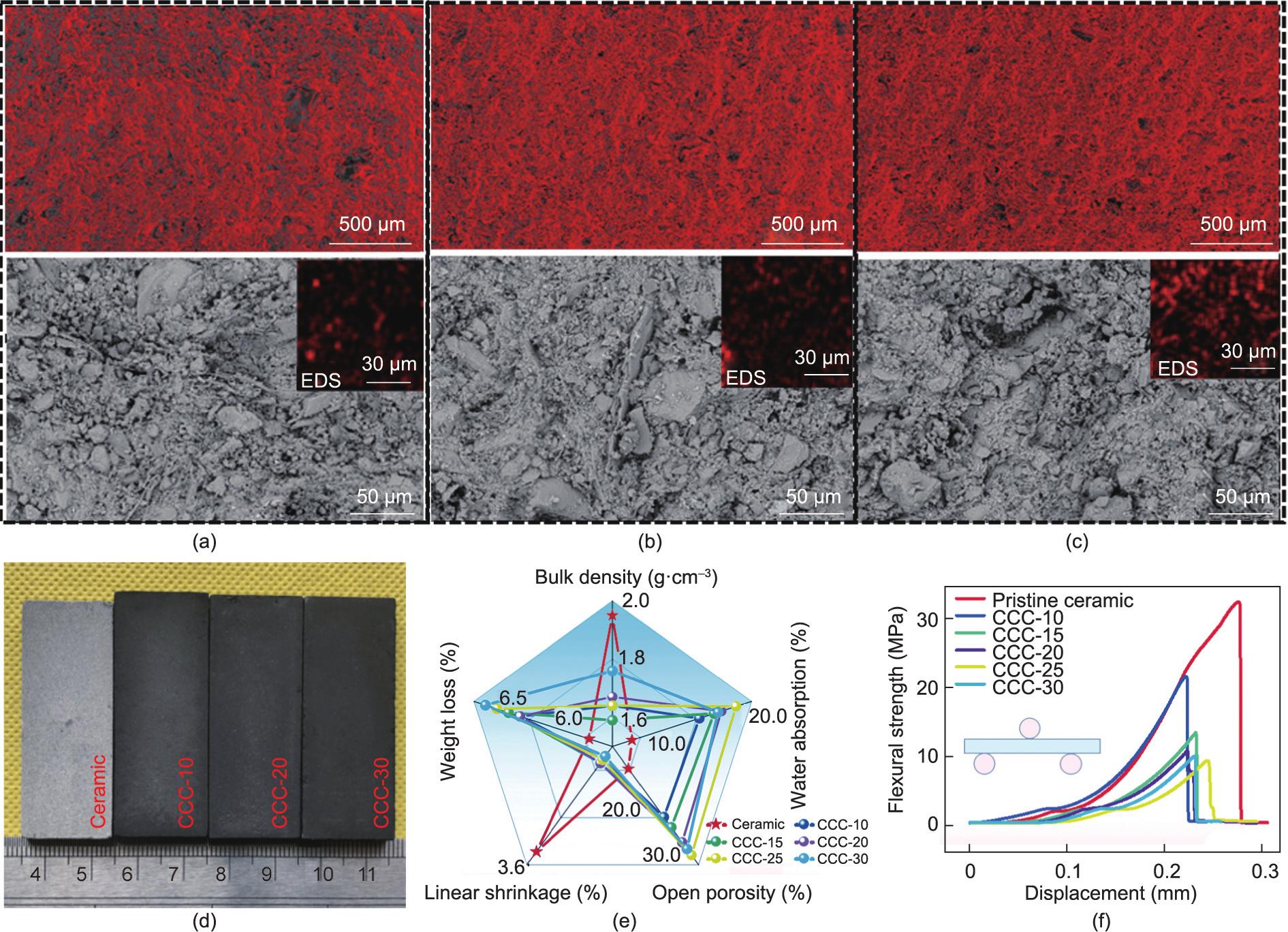
Fig. 2. Cross-section SEM images of (a) CCC-10, (b) CCC-20, and (c) CCC-30. Corresponding red SEM images of composites were analyzed using ImageJ. Physical properties of composites and pristine ceramic: (d) optical images; (e) bulk density, open porosity, water absorption, linear shrinkage, and weight loss; and (f) flexural strength.
The pristine ceramic was gray, whereas the CCCs (CCC-10, CCC20, and CCC-30) were black (Fig. 2(d)). The pristine ceramic showed a higher linear shrinkage (3.4%) than the composites (0.5%–0.7%) (Fig. S2(e) in Appendix A); this may be because the cured phenolic resin can inhibit shrinkage by distributing the pressure associated with ceramic matrix shrinkage during heat treatment [46]. As shown in Fig. 2(e) and Fig. S2, the pristine ceramic showed a bulk density of 1.95 g·cm–3 , open porosity of 16.3%, and water absorption of 7.4%. Meanwhile, the obtained composites showed a bulk density of 1.64–1.76 g·cm–3 , open porosity of 25.7%–33.1%, and water absorption of 15.6%–20.1%. The weight loss of the composites increased with the phenolic resin content, which may be attributed to resin carbonization. The weight loss of the pristine ceramic was 5.8%, which was similar to that of the CCCs (6.4% for CCC-10 and 6.7% for CCC-30); this may be because the phenolic resin constituted an extremely low proportion of the composites, and the weight in the phenolic resin solution was primarily that of the solvent ethanol. Therefore, the actual weight of the resin decomposed via heat treatment was extremely low in all the CCC samples.
After heat treatment, the phenolic resin was successfully carbonized, and the residue yield was measured via thermogravimetric analysis (TGA), as shown in Fig. S3 in Appendix A. CCC-10 indicated the lowest residue yield (2.3%), whereas CCC-30 indicated the highest residue yield (4.8%).
The flexural-strain curves show the typical flexural properties of both the pristine ceramic and the composites (Fig. 2(f)). The pristine ceramic showed a flexural strength of 32.4 MPa. Owing to the porous structure, the obtained composites indicated reduced flexural strength in comparison with the pristine ceramic. The flexural strength of CCC-10 was 21.4 MPa. As the phenolic resin content increased, the flexural strength of the obtained composites decreased gradually, that is, 13.1 and 9.8 MPa for CCC-15 and CCC-30, respectively. It is noteworthy that a flexural strength of approximately 10 MPa satisfies the strength requirement for daily heating applications.
《Fig. 3》
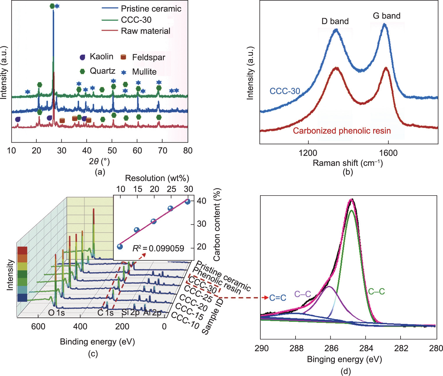
Fig. 3. (a) XRD patterns of ceramic precursor and CCC-30 after firing process; (b) Raman spectra of CCC-30 and carbonized phenolic resin; (c) XPS survey spectra of composites; (d) C 1s XPS analysis of CCC-30.
《3.2. Structural characterization and component analysis》
3.2. Structural characterization and component analysis
Table 1 shows that the main chemical components of the ceramic precursors were SiO2 and Al2O3, which are the main components of kaolin. The ceramic precursors contained low amounts of metal oxides, primarily from feldspar, which was used to reduce the temperature during heat treatment. The XRD patterns of the pristine ceramic and CCC-30 show the same peaks assigned to the ceramic (Fig. 3(a)). Compared with the ceramic precursors, a new mullite phase was successfully formed after the heat treatment. Meanwhile, the kaolin and feldspar mineral phases almost vanished in the XRD patterns of the pristine ceramic and CCC-30 [47,48]. These results indicate that the presence of carbonized phenolic resin did not significantly affect the crystallization structure of the composites.
The evolution of phenolic resin in CCC-30 and pristine phenolic resin at high temperatures was analyzed using Raman spectroscopy. As shown in Fig. 3(b), both CCC-30 and the directly carbonized phenolic resin exhibited typical features of carbonaceous material with two overlapping peaks at approximately 1343 cm–1 (D band) and 1576 cm–1 (G band), which is attributed to the characteristics of disordered carbon and ordered graphitic crystallites [49–51]. The results show that the phenolic resin in CCC-30 can be successfully carbonized. The intensity ratio of the D and G peaks (ID/IG) was used to analyze the disordered structure of the carbonaceous material. CCC-30 had a slightly lower ID/IG value (0.96) than the directly carbonized phenolic resin (1.00), which indicates that the synergistic effect of carbonization and ceramicization may promote the formation of graphite structures in carbon crystallites [52].
The chemical compositions and atomic percentages of carbon were investigated using XPS (Fig. 3(c)). The characteristic XPS peaks of the composites were observed at approximately 85.5, 110.5, 291.6, and 545.5 eV. Peaks corresponding to Al 2p (85.5 eV) and Si 2p (110.5 eV) were observed in both the composites and pristine ceramic, which may be attributed to the inorganic nonmetal oxide (mullite and quartz). The peaks at 291.6 eV assigned to C 1s appeared in both composites and carbonized resin, indicating that the phenolic resin in the composites was carbonized successfully by heat treatment. Furthermore, it was discovered that the atomic percentages of carbon in the composites were correlated linearly with the phenolic resin content (R2 = 0.99059), which is consistent with the TGA results. For the C 1s XPS curve of CCC-30 (Fig. 3(d)), the peaks at approximately 284.9, 286.1, and 288.1 eV were ascribed to C–C, C–O and C@O, respectively [53–55]. These results further verified that the phenolic resin inside the composites was effectively carbonized through heat treatment.
《3.3. Evaluation of electro-thermal performance》
3.3. Evaluation of electro-thermal performance
The electro-thermal properties of the composites were evaluated (Fig. 4). It was discovered that the electrical resistance of the composites decreased with increasing phenol resin content (Fig. 4(a)). CCC-10 indicated the highest electrical resistance of 79.7 Ω·cm–1 , whereas the electrical resistance of CCC-15 reduced significantly to 15.1 Ω·cm–1 , which implies that the electrical percolation threshold of the composites may range between 10 wt% and 15 wt%. As the content of phenolic resin continued to increase, CCC-30 exhibited the lowest electrical resistance of 4.6 Ω·cm–1 . Therefore, CCC-30 displayed the best electro-thermal performance, as shown in Fig. 4(b). The temperature–time curve describes the typical resistance Joule heating law. The surface temperature of the composites increased rapidly in the early stage once an 8 V voltage was applied. The heating rate decelerated during the subsequent heating process, and the temperature of the composite stabilized. In addition, the lower the resistance of the composites, the higher was the stabilized temperature. When the phenolic resin content increased from 10% to 30%, the stabilized temperatures of CCC-10 and CCC-30 under an 8 V voltage were 45.2 and 188 °C, respectively. CCC-30 demonstrated the best Joule heating performance among all the samples. The corresponding electro-thermal performances under different voltages are shown in Fig. 4(c). When a lower voltage of 4 V was applied, the temperature of CCC-30 reached 66.5 °C, which satisfies the requirement for indoor heating. When higher voltages of 8 and 12 V were applied, the composite reached 188 and 386 °C, respectively. As the applied voltage was increased further to 16 and 20 V, the temperature of CCC-30 increased rapidly to 400 °C after 74 and 48 s, respectively, which indicates the potential of the CCCs as heating elements. The cyclic electro-thermal performance of CCC-30 at different voltages is presented in Fig. 4(d). The heating/cooling rate and stabilized temperature were maintained well during the power on–off cyclic tests at 4, 8, and 12 V. Excellent heating stability and durability can ensure its reliability for long-term use.
《Fig. 4》
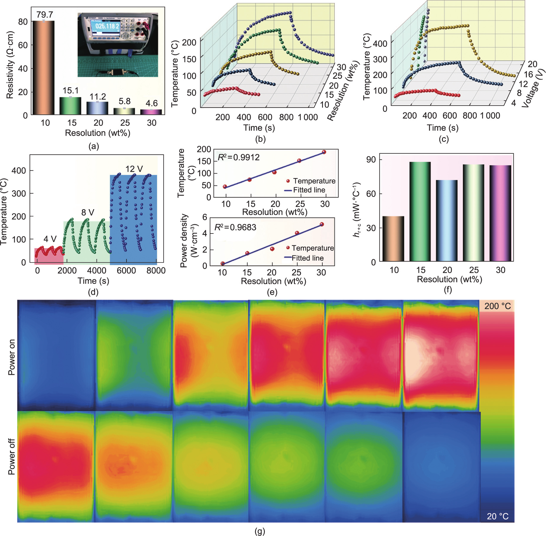
Fig. 4. Electro-thermal performance of composites. (a) Resistance change; (b) temperature–time curve under 8 V; (c) temperature–time of CCC-30 under different voltages; (d) cyclic performance of CCC-30 under different voltages; (e) temperature/power density–resolution curves of CCCs under 8 V; (f) energy consumption resolution curve under 8 V; (g) thermal images of CCC-30 under 8 V.
According to the Joule heating theory, the heat generated (Qg) by the composites can be expressed as follows [56,57]:

where U, R, and t are the applied voltage, resistance of the composites, and heating time, respectively. Qg comprises the stored heat (Qs) and dissipated heat (Qd).

Here, Qs can be estimated as follows:

where C and m represent the heat capacity and mass of the conductive composites, respectively; Ts and Ti are the stabilized and initial temperatures of the conductive composites, respectively. Because the ceramic matrix is the main component of the composites, we assumed that the C and m values of each composite were the same. The dissipated heat Qd can be categorized into heat transfer from radiation and air convection. The radiative heat loss is negligible compared with the air convective heat loss, where air convection (Qac) is the main mechanism of heat dissipation. Hence, Qac can be estimated as follows:

where Qac is associated with the heat transfer coefficient and the surface of the composites. Based on the equations above, Ts can be expressed as
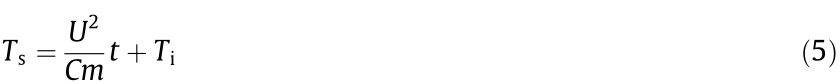
As shown in Eq. (5), the stabilized temperature of the composites is proportional to the reciprocal of the resistance under a constant voltage. Fig. 4(a) shows that the reciprocal of the resistance is proportional to the phenolic resin content, indicating that the resin content is proportional to the stabilized temperature achieved by the composites (Figs. 4(b) and (e)). In addition, the power density shows a good linear correlation with the phenolic resin content (Fig. 4(e)). Energy efficiency is an important parameter for a Joule heater, where a positive correlation is exhibited between the heat transferred by radiation and convection (Hr+c value). The composites indicate a low Hr+c value, that is, only 85.2 mW· °C–1 under 8 V for CCC-30 (Fig. 4(f)).
The heat distribution of CCC-30 in the heating–cooling cycle at 8 V was observed via thermal imaging. Compared with textilebased carbon fiber/ceramic composites in which heat from the electro-thermal effect is concentrated above the carbon fiber, the heat distribution of CCC-30 is distributed more evenly across the entire composite. This is primarily attributed to the homogeneous distribution of the heating element (carbonized phenolic resin) in the composite.
《3.4. Applications》
3.4. Applications
The excellent electro-thermal performance of the CCCs render them a potential candidate for application in multiple Joule heating applications involving ceramics. Deicing is particularly important for facilities in cold regions. CCC-30 demonstrated efficient deicing performance (Video S1 in Appendix A). It melted 100 g of ice under 20 V within 7 min (Fig. 5(a)), suggesting that the fabricated CCCs are applicable to self-heating deicing equipment. In addition, CCC-30 boiled 150 mL of water within 15 min at 20 V (Fig. 5(b)), which implies that the composite can be used as electric heating kettles or warm teacups. Ceramics are used in non-stick pots and pans owing to their smooth surfaces and thermal conductivities. Fig. 5(c) shows that CCC-30 can be used as a frying pan for cooking beef and quail eggs.
The electro-thermal properties of the fabricated CCCs can be adjusted by changing the wiring modes, including the series and parallel circuits. Fig. 5(d) shows that multiple CCC-30 samples (50 mm × 20 mm) can be connected via a parallel circuit. The thermal images show an even heat distribution. The total resistance (Rt) of the parallel resistance can be expressed as follows:

Here, RCCC is the resistance of CCC-30, and n is the number of CCC-30 composites. The increase in the number of parallel CCC30 composites resulted in a decrease in the total resistance, which consequently increased the surface temperature under a constant voltage within the same power-on time (Fig. 5(d)). Therefore, the electro-thermal performance and energy consumption can be adjusted by controlling the electrical circuit arrangement (series and parallel circuits) and the number of CCCs.
《Fig. 5》

Fig. 5. Applications of CCC-30 in Joule heating: (a) deicing; (b) boiling water; (c) cooking; and (d) series and parallel circuits for Joule heating.
Carbonaceous materials with favorable electromagnetic absorption properties and low density are ideal fillers for ceramics-based composites used in EMI shielding. The EMI shielding performance is positively correlated with the electrical conductivity. The pristine ceramic exhibited the lowest total shielding (SEt), that is, 3.9 dB at 8.2 GHz, among all the ceramic samples (Fig. 6(a)). As the phenolic resin content in the composites increased, the SEt of CCC-10, CCC-20, and CCC-30 increased to 10.0, 17.8, and 26.2 dB at 8.2 GHz, respectively. The main EMI shielding mechanism of the composites was the absorption of waves by carbonized phenolic resin. The absorbing shielding (SEa) of the composites exhibited a good linear relationship with the phenolic resin content, that is, it increased from 5.08 dB of CCC-10 to 19.10 dB of CCC-30 under the same conditions (Fig. 6(b)). Meanwhile, the reflection shielding (SEr) of the composites was slightly higher than that of the pristine ceramic, which may be due to the porous structure of the composites. Relatively stable chemical stability, superb mechanical strength, high thermal stability, and simple preparation method promote the application of CCCs in EMI shielding.
In addition, the presence of carbonized materials in CCCs imparts a photothermal conversion effect to the ceramic composites. The photothermal conversion performance of CCC-30 and the pristine ceramic was analyzed under simulated sunlight (Figs. 6(c) and (d)). After 20 min of light irradiation, the surface temperature of CCC-30 was 48.4 °C, which is higher than that of the pristine ceramic (43.8 °C). Therefore, CCCs with a certain photothermal conversion function can be used for auxiliary heating.
《Fig. 6》

Fig. 6. EMI shielding performance: (a) total shielding; (b) absorbing shielding–reflection shielding (SEr) contributions and photothermal conversion performance of CCC-30: (c) thermal images; and (d) temperature–time curve.
《4. Conclusions》
4. Conclusions
In summary, a facile, cost-effective, and scalable method was developed to fabricate CCCs by integrating phenolic resin solution into ceramic precursor, followed by conventional dry pressing and heat treatment. The carbonization of phenolic resin inside CCCs and the ceramization of ceramic precursors were achieved simultaneously during heat treatment. The presence of carbonized materials improved the electrical properties of the ceramic composites. The uniform distribution of the carbonized material in the composites resulted in an even heat distribution under a certain voltage. CCC-30 afforded a maximum temperature of 386 °C at 12 V after 10 min and 400 °C under 20 V after 48 s, indicating excellent electro-thermal performance. The electro-thermal performance correlated linearly with the resin phenolic content and can be adjusted by changing the electrical circuit arrangement (series and parallel circuits). Moreover, CCC-30 exhibited favorable EMI shielding performance, that, 26.2 dB at 8.2 GHz. This study provides a novel strategy for fabricating electro-thermal ceramic composites via a simple single-step firing process. The excellent electro-thermal performance and reliable stability of the CCCs will further promote their use in practical applications, such as deicing, boiling water, and cooking.
《Acknowledgments》
Acknowledgments
This study was supported by grants from the National Natural Science Foundation of China (52078394).
《Compliance with ethics guidelines》
Compliance with ethics guidelines
Daiqi Li, Bin Tang, Deshan Cheng, Jing Wu, Wenyang Tang, Zhao Zhong, Jianqiang Li, Guangming Cai, Jinfeng Wang, and Xungai Wang declare that they have no conflict of interest or financial conflicts to disclose.
《Appendix A. Supplementary data》
Appendix A. Supplementary data
Supplementary data to this article can be found online at https://doi.org/10.1016/j.eng.2021.12.017.


 京公网安备 11010502051620号


