
《1. Introduction》
1. Introduction
Recent developments in implantable electronics technology have created a unique opportunity to improve diagnostic and therapeutic procedures in medical practice. Bioelectronics comprise one of the key facets of implantable electronics. They are designed to operate inside the human body and can transmit electrical pulses to manipulate organ functions and neural activities, in the form of brain stimulators, pacemakers, and cochlear and retinal implants (Fig. 1) [1–4]. Extensive research is being conducted to devise flexible, nontoxic, biocompatible, cost-effective, and smallform-factor bioelectronics to extract physiological information from neural signals for treating a wide range of disorders [5–7]. Although they are typically considered as implants, their wearable applications have been the subject of recent interest [8]. A typical bioelectronic device offering multifunctional capabilities comprises ① power sources or batteries, ② antenna systems [9,10], ③ control circuitry, ④ mechanically stable tiny reservoirs for carrying drug formulations [11,12], and ⑤ ultralow-power electronics [13,14].
《Fig. 1》

Fig. 1. (a) Schematic of wirelessly controlled bioelectronic devices for organ specific therapeutic and diagnostic applications. (b) On-body transmitting antenna is wirelessly connected with a bioelectronic device. The wireless connection can be used to perform multiple functions, including wireless power transfer (WPT) and data communication. WPT powers the device, obviating a battery. Bidirectional data communication is used for real-time monitoring of a device performance and its control.
The antenna system and associated wireless circuitry offer a noninvasive way of transferring a plethora of real-time data, including physiological information, organ health, and device status to the external unit. Wireless functionality, therefore, offers convenience, unlike devices that require a surgical operation for data extraction. However, electromagnetic signals undergo attenuation and absorption while propagating through body tissues, deteriorating the device performance with respect to efficient and robust wireless data transfer links [15]. Several strategies to reduce path loss through the body have been presented in the literature [16]. It is well known that body tissues allow effective propagation of electromagnetic waves at low frequencies [17]; however, this comes at the cost of large antennas. Stringent miniaturization requirements, however, constrain the integration of antennas within the compact space available [18,19]. Shaping the antenna design has thus been of paramount importance not only for miniaturization, but also considering the adverse impacts on radiation efficiency that are already exacerbated by the lossy body tissues [20–22]. Antenna miniaturization techniques have focused on low-frequency bands, including medical implant communication service (402–405 MHz), industrial scientific and medical (ISM) band [23,24], and MedRadio (401–406 MHz) [23,25–27] for optimal signal strengths at the receiving unit. Furthermore, bioelectronic antennas have been proposed for very low frequencies, such as 13.56 MHz [28–30] and 5 MHz [12].
Microfabrication technologies and burgeoning interest in flexible materials have also permeated in the development of hybrid, biocompatible, conformal, miniaturized, efficient, and soft antennas, paving the way for their seamless integration in bioelectronic devices [1,2,8,31,32]. Although bioelectronics can effectively modulate neural activity, their lifespan is limited. Energy harvesting, including the use of piezoelectric [33,34], thermoelectric [35], and biopotential [36] techniques, have been utilized as potential alternatives to traditional battery sources. Although these techniques can reduce the overall volume, the generated power density is insufficient for continuous operation. Wireless power transfer (WPT) techniques based on near-field electromagnetic coupling have recently been implemented for bioelectronics, offering diverse functionalities and longer use while eliminating the constraints associated with battery power [37,38]. Considerable attempts are still being made to devise efficient antenna designs for bioelectronic devices, with the aim of reshaping their WPT capabilities.
This review highlights recent advances in antenna systems, particularly those designed for wireless bioelectronic devices. The emphasis of this paper is on antenna design in the context of biocompatible materials, packaging, fabrication methods, operating frequency, and radiation characteristics. Subsequent sections discuss different organs of the body that can benefit from their potential use in diagnostic and therapeutic applications.
This review paper is replete with a natural language processing (NLP)-assisted survey strategy; analyzing a great amount of relevant literature, including key studies and their findings that humans unassisted may have overlooked. Our NLP-based text summary technique can automatically extract the key ideas or most relevant information within the scope of the original content, which has been validated using the Rouge matrix. Using these validated NLP-generated summaries, the authors improved the scope of this review.
《2. Gastrointestinal tract monitoring》
2. Gastrointestinal tract monitoring
The gastrointestinal (GI) tract can elucidate the seminal physiology of almost every organ in the human body [18]. The common disorders associated with the GI tract include dysphagia, gastroesophageal reflux disease, functional dyspepsia, gastroparesis, chronic intestinal pseudo-obstruction, and irritable bowel syndrome [39]. For the treatment of such disorders, ingestible bioelectronic devices, including an endoscope [3], three dimension (3D) printed gastric electronics [40], bacterial electronic systems [41], ingestible hydrogels [42], and wireless capsule endoscope devices [23,43–45] have recently been discussed. Some of these devices are commercialized and readily accepted as a clinical procedure, assisting medical experts in the diagnosis and early detection of these disorders in a noninvasive fashion. For instance, a typical capsule endoscope device can detect biomolecules in real-time and send high-resolution images from inside the body to an external physician over a wireless link [23,46,47]. A physician can interpret these images to diagnose a wide range of disorders or ailments and can prescribe treatment accordingly [48].
An ingestible device can have sensors, battery units, antennas, cameras, and many other electronic components [49]. Numerous materials and fabrication methods have been explored in the literature to realize miniaturization [50]. The emerging 3D printing technology has also been envisioned to fabricate miniaturized gastric electronics (Fig. 2(a)) [40]. However, the integration of the antenna with an optimal efficiency for reliable wireless communication with the external unit has remained a major challenge. A wide array of antenna designs has been studied in the literature for ingestible devices [19,23,44,45,51–65], and their seamless integration around the conformal shape of a device is achieved using flexible materials (Fig. 2(b)) [66,67]. Meandered structures have often been proposed for ingestible conformal antennas owing to their ability to resonate at low frequencies while occupying limited space [23,68]. Apart from conformal structures, few ingestible bioelectronic devices have been fabricated with embedded antennas for WPT and communication (Fig. 2(c)) [69]. Some studies have reported transient and biodegradable printed antennas on cellulose fibers or biodegradable composite films to improve the radiation characteristics of ingestible antennas [70,71].
《Fig. 2》

Fig. 2. Ingestible bioelectronic devices. (a) 3D printed gastric electronics with drug delivery modules. The inset image shows integration of an antenna operating at a Bluetooth radio frequency (RF) of 2.4 GHz [40]. (b) Fabricated loop antenna conformed around the capsule shaped device for wireless endoscopy. (c) Integration of components (programmable load resistor (digitally controlled potentiometer (DCP)), crystal (XTAL), microcontroller (μP), RF matching network (MATCH), and antenna (ANT) on the front side, with the battery (BATT) and decoupling capacitor (CAP) on the reverse side) over a printed circuit board (PCB). The PCB is embedded in a capsule-shaped ingestible device. (b) Reproduced from Ref. [23] with the permission of IEEE, ©2019; (c) reproduced from Ref. [69] with the permission of Springer Nature, ©2017.
Impedance matching of an antenna with the rest of the electronic circuitry is a major design criterion for transmitting and receiving wireless signals with high reliability. The dielectric properties of body tissues vary with frequency and can thus detune the antenna resonant frequency. An adaptable and wideband impedance matching network can be an effective alternative for implantable and ingestible antennas that can experience detuning in the presence of lossy body tissues [72]. Moreover, ingestible electronics can undergo random orientation while moving through the digestive tract. In this context, circular [60] and dual-polarized [73] omnidirectional antennas have been proposed in the literature to mitigate the loss of communication links with external units. To track a device location in the digestive tract, localization techniques that focus on analyzing the received signal strength at the external unit are employed [43,48].
Despite considerable progress in wirelessly controlled ingestible bioelectronics, the challenges associated with limited battery capacity lower their operation time. Biocompatible batteries have been considered in the literature for implants; however, they increase the overall device size and are, thus, inconvenient. As an alternative, WPT has been considered a paramount strategy for ingestible bioelectronics [69,74,75].
《3. Retinal prosthesis》
3. Retinal prosthesis
Ocular diseases, such as macular degeneration (MD) and retinitis pigmentosa (RP) mostly affect the vision of the aging population and can lead to complete blindness or visual dysfunction [76,77]. The limited space in the human retina is a major bottleneck in the treatment of ocular diseases. Moreover, retinal implants with connected wires are considered infeasible owing to the risk of infections. Therefore, wireless technology for retinal prosthesis has been extensively reported to enable wireless control of the implant functions [78–87].
A quintessential system for retinal prosthesis encompasses extraocular and implanted intraocular systems [77]. The visual data are captured using the extraocular system and transmitted wirelessly through an antenna system, whereas the intraocular system consists of an electrode array, antenna, and a signal processing unit [88,89]. An antenna is used to establish wireless links between the extraocular and intraocular systems, as well as for power transfer [81]. Compact antennas are preferred for retinal implants, and their size miniaturization techniques, such as meandered microstrip lines [90], wires [91], and folded dipoles [92], have been extensively discussed in the literature. Nonetheless, miniaturization techniques, which are essential for integrating the antenna within an intraocular unit, often result in a narrow bandwidth and low gain. A triangular-shaped microstrip patch antenna was reported in Ref. [77] to enhance the bandwidth of the implanted and external subsystems for wireless retinal prosthesis.
An epiretinal implant was reported in Refs. [93,94] for the electrical stimulation of retinal neurons. The device is assimilated with a receiving (Rx) coil, electronics, and electrode array and is surgically implanted around the eye. The transmission (Tx) coil is integrated into the external glasses, which also has a video processing unit (VPU), video camera, and coil. The Tx coil transmits the processed video image data to the Rx coil mounted around the eye. The amplitude modulation at 3.156 MHz is used for data communication between the Tx and Rx coils as well as for WPT. In another study, it was demonstrated that the placement of a coil-based antenna in the anterior aspect of the retina can enhance the inductive coupling efficiency with the primary coil (Fig. 3(a)) [95]. This is mainly because the anterior aspect has more space than the temporal side of the eye. For this reason, a relatively large coil can be implanted, thus potentially improving radiation characteristics. To mitigate any infection in the surrounding tissues, the coils are wound on a spherical mandrel, which resembles the curvature of the eye. The coils were fabricated using gold and spherically formed to match the eye curvature, as shown in Fig. 3(b).
In the context of wide bandwidth, compact microstrip antennas have been investigated for dual-unit retinal prosthesis at operating frequencies of 1.45 and 2.45 GHz [77]. For the extraocular unit, a planar inverted-F antenna (PIFA) is designed on a pair of glasses, whereas equilateral triangular microstrip intraocular antennas are designed to integrate within the compact ciliary muscles of the eye. The coupling performance of a wireless link was evaluated in the presence of a human head model, whereas an eye phantom was used to perform measurements.
《Fig. 3》

Fig. 3. Retinal prosthesis and associated primary power and data coils. (a) Prototype of the device. The model of an eye is fabricated with plastic material; the power and data coils are made of gold material. (b) The external primary coils are potted in polydimethylsiloxane (PDMS). Reproduced from Ref. [95] with the permission of IEEE, ©2011.
《4. Cochlear implants for auditory nerve stimulation》
4. Cochlear implants for auditory nerve stimulation
Hearing loss is related to sensory-neurological disorders that can affect the lifestyle of people [96,97]. Hearing aids in the form of implants have been successfully commercialized over the last few decades and have transformed cochlear treatment. They are capable of restoring the hearing by stimulating the auditory nerve with electrical signals [98–100].
A wireless cochlear implant features external and internal units that are coupled through coils (Fig. 4) [101]. The external unit is used to process the acoustic signals and then generate stimulation patterns in the frequency range of hearing loss [101]. These patterns are wirelessly transmitted from an external unit to the implant over a low-frequency signal (Fig. 4). The received signal is demodulated and processed to generate electric currents through an electrode array and are threaded into the cochlea to stimulate the auditory nerve. The bidirectional communication between the external and implanted units is critical for effective transmission of stimulating patterns, as well as for WPT.
《Fig. 4》

Fig. 4. Schematic and components of the cochlear implant and its wireless connectivity with external unit. DSP: digital signal processor; LSK: load-shift keying; BPSK: binary phase-shift keying; POPA: programmable output power amplifier; ILPS: inductive link power supply; DAC: digital to analog converter; CDR: charging data record. Reproduced from Ref. [101] with the permission of IEEE, ©2019.
Coils are mainly deployed in cochlear implants owing to their ability to communicate effectively through magnetic fields in near-field communications (NFCs) [101,102]. However, they often suffer from various electromagnetic interference issues. To overcome this limitation, a shielding coil is proposed for the transmitting coil of a cochlear implant [102].
Several other types of antennas have been discussed in the Refs. [96,103,104]. Loop antenna designs operating in the ISM band were reported in Refs. [96,104]. Furthermore, to realize high-data-rate communication and an ultra-wideband transceiver was reported in Ref. [103]. The overall system consumes low power owing to the ultra-wideband transceiver characteristics.
《5. Hyperthermia treatment》
5. Hyperthermia treatment
Hyperthermia treatment is a thermal therapy technique that exploits the thermal response of body tissues in confining heat to ablate tumors with electric current-induced Joule heating [105–111]. In clinical practice, it is occasionally implemented in conjunction with chemotherapy or radiotherapy. Recently, wirelessly controlled stents have been reported for hyperthermia treatment [112–114]. They serve as heaters and resonate only when the external radio frequency (RF) is matched to their own resonance. In a recent report, a gold-coated stent was presented in the form of an inductor and integrated with a capacitor microchip [112]. The entire stent was packaged with a 40 μm thick Parylene C film and excited with an external omnidirectional antenna system. The in vitro experiments confirmed the ability of the stent to generate heat in response to external RF power.
A similar approach was discussed in Ref. [113] for wireless endohyperthermia treatment, where a stent acts as a frequencyselective wireless heater (Fig. 5). It features an inductor–capacitor (LC) tank circuit that is tuned to external RF fields, originating from a loop antenna (diameter of 12 cm). Upon heating, the stent applies stress to generate neointimal hyperplasia for in-stent restenosis. A biocompatible (1.5 mm × 2 mm × 0.6 mm) circuit breaker approach based on balloon catheters to control the temperature rise in a stent was discussed in Ref. [115]. The circuit breaker incorporates an embedded capacitor. A micromachined shape memory alloy cantilever was used as a thermoresponsive switch to turn the circuit breaker on and off. An interesting approach of using the stent as an antenna was reported in Ref. [116]. The stent is not only used for endohyperthermia treatment; its potential to establish wireless data and power transfer links is experimentally demonstrated at ISM bands of 915 MHz and 2.45 GHz. The entire device utilizes only an application-specific integrated circuit and is fabricated with a 0.13 μm complementary metal oxide semiconductor (CMOS) process within 1.56 mm2 . The overall system is capable of harvesting RF power from incident waves at 2.4 GHz, whereas it transmits data at the 915 MHz band.
《Fig. 5》

Fig. 5. Fabricated active-stent device for wireless endohyperthermia treatment of restenosis. PI: polyimide. Reproduced from Ref. [113] with the permission of Elsevier, ©2015.
《6. Cardiovascular healthcare》
6. Cardiovascular healthcare
Cardiovascular diseases (CVDs) are associated with the heart and blood vessels, and globally affect human life expectancy. For this reason, real-time monitoring of heart functions using bioelectronics has been extensively considered in the recent past for early CVD detection [117–122]. Soft and flexible materials have been used in the fabrication of continuous cardiac monitoring devices, such as cardiac pacing, robotic sleeves, and electronic stents [119]. Many of these devices are equipped with a wireless control unit for transmitting heart rhythms to an external unit, which is convenient for cardiac monitoring, unlike traditional wearable electrocardiogram (ECG) equipment that requires several wires for mating sensors to the body [121,123–127].
The aforementioned advantages of wireless cardiac monitors have opened immense opportunities for antenna designs that can perform bidirectional data communication [128–130] and WPT [131–134]. Coil- [129,131–138], loop- [139], monopole- [140], patch- [141], and circumferential- [142] shaped antenna designs for cardiac pacemakers are often discussed in the literature, whereas the most common approaches for data communication are based on NFC [4,121,143] and RF identification (RFID).
A flexible antenna design was reported in Ref. [121] for a soft cardiac wearable sensor that can transfer data to an external smartphone (Fig. 6(a)). In another study, a PIFA was proposed for an artificial cardiac pacemaker operating at 403 MHz [144]. The antenna demonstrated wide impedance bandwidth characteristics and was fed with a coplanar waveguide. The resonant frequency of the antenna is controlled by an L-shaped split. The dimensions of the entire pacemaker configuration were 30 mm × 35 mm × 7 mm. The antenna performance was evaluated in a humanequivalent tissue phantom, demonstrating a peak gain of –24.61 dBi at 403 MHz.
《Fig. 6》

Fig. 6. Bioelectronic devices for cardiovascular healthcare. (a) Schematic of the wearable cardiac sensor device. The integration of multiple components and layers are presented. The flexible antenna is fabricated on the PI substrate with the NFC and battery module. (b) Prototype of the rectenna based pacemaker. (i) Manufactured rectenna; (ii) manufactured pacing circuit with charging element; (iii) schematic of the leadless pacemaker before its integration; (iv) front view of the complete fabricated pacemaker; (v) pin couple for implantation in the tissue. (c) Fabricated 1 × 2 transmit array connected with a corporate feed network (top), and D shaped slots that are etched on the ground plane (bottom). Dimensions (in mm) are W1 = 9.91, W2 = 7.8, W3 = 4.25, W4 = 2.8, L1 = 60.5, L2 = 55.6, and R = 45. (a) Reproduced from Ref. [121] with the permission of Springer Nature, ©2018; (b) and (c) reproduced from Ref. [139] with the permission of IEEE, ©2019.
A radio transceiver was envisioned in an implantable programmable controller at 433 MHz [145]. To overcome the challenges associated with a limited battery life, an implantable rectenna operating at 954 MHz was proposed for a cardiac pacemaker (Fig. 6(b)) [139]. The rectenna is realized with a planar dipole antenna constructed with hexagonal fractals and assimilated with an impedance matching and rectifier circuit. For miniaturization, rectangular strips are organized in an antenna structure along with a high-permittivity dielectric substrate ( = 9.8). To demonstrate the WPT capability of the system, a wearable transmit antenna array (1 × 2) was fabricated using conducting strips (Fig. 6(c)). The ground plane of the structure was truncated to realize a directional beam and good impedance matching. The low thickness (0.254 mm) of the substrate helps to conform the antenna array over the test subject body. The in vivo testing of a pacemaker was performed using the Dorset breed model (Fig. 7(a)) [139]. The wearable transmit array was placed over the chest, transmitting an RF power of 21 dBm to the implant. The rectified direct current (DC) voltages measured by the rectenna as a function of the input RF power are shown in Fig. 7(b) [141].
《Fig. 7》
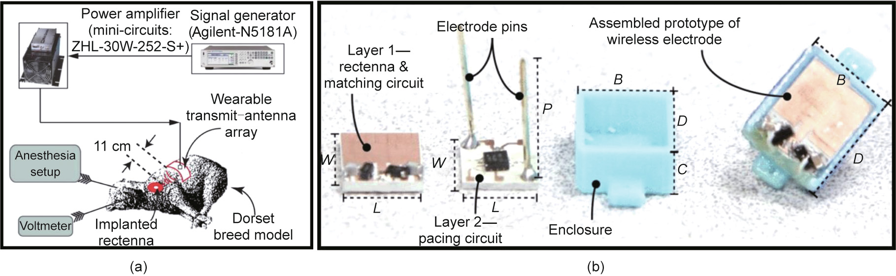
Fig. 7. (a) Illustration of the in vivo experiment setup that is used to test the pacemaker in the Dorset breed model. The transmit array is connected to the power amplifier and signal generator. (b) Prototype of batteryless and implantable wireless asynchronous pacing system. Different fabricated components of the system are presented, with dimensions (in mm) of W = 12, L = 10, P = 15, B = 12.4, C = 4.5, and D = 14.4. (a) Reproduced from Ref. [139] with the permission of IEEE, ©2019; (b) reproduced from Ref. [141] with the permission of IEEE, ©2019.
A similar rectenna-based approach has been reported for a batteryless asynchronous cardiac pacing system [141]. The implant consists of an electrode antenna (resonating at 1.2 GHz), an impedance matching circuit, and a rectifier. For the antenna, a planar microstrip topology is utilized and integrated with a complementary split-ring resonator: The overall system dimensions are 10 mm × 10 mm. An external horn antenna was used to transfer RF power to the implant, with 25 cm between them. The system was implanted over the epicardial surface of the left ventricle in an ovine subject. The antenna performance was evaluated in an implantable scenario. It is reported that the return loss of the antenna is –17 dB at 1.25 GHz, whereas the measured realized gain is –1.5 dBi. The external horn antenna transmits an RF power of 10 dBm, generating 0.0082 mW∙cm–2 at the implant location.
《7. Drug delivery devices》
7. Drug delivery devices
Drug delivery systems are capable of transferring therapeutic agents to the targeted location with optimal efficacy and pharmacokinetics [11]. They can perform multiple functions related to dosing and can tailor drug release kinetics in real time to achieve the desired concentrations and diffusion rates in the human body. Several electronic components and materials have shown potential to support drug delivery with enhanced patient compliance, adaptability, and drug safety [146]. Passive [147] and active [148] drug release mechanisms have been reported. Active systems are more commercialized than passive systems, which suffer from low drug concentrations and small actuation forces and require complex system packaging [149]. Currently, most active systems are wirelessly controlled, granting patients autonomy over the drug release time, and allowing the dosing schedule to be tailored by programming the device wirelessly [150–153].
Wireless control of the drug release mechanism can open new frontiers for therapeutic treatment. In this context, several wirelessly controlled drug delivery platforms have shown potential for treating a plethora of ailments related to hormone imbalances, malignant cancers, and others [11]. Recent innovations in microfabrication technologies have enabled the integration and packaging of electronics, materials, microprocessor controllers, antennas, and RF circuits within the compact space of a device [146]. All these components are assimilated along with small reservoirs to store drugs. Thus, this device configuration requires a compact antenna design to allow enough space for the integration of reservoirs and other electronic components. With the emergence of flexible biocompatible materials, it has become possible to fabricate conformal antennas that can adapt to the shape of the device [154].
The bidirectional communication link between the device and external unit can share information about the battery voltage status, drug diffusion rate, and release time [154]. Hence, an efficient antenna design is indispensable for achieving reliable and robust links through the human body. In a recently published report, a device based on bioresorbable polyanhydride reservoirs was demonstrated for drug delivery, and it could be wirelessly powered over inductive links (Fig. 8(a)) [12]. The RF power harvesting unit consists of a magnesium (Mg) RF coil, a silicon nanomembrane (SiNM), and a parallel plate capacitor (Fig. 8(b)). The quality factor of a coil is approximately 15, which can induce sufficient voltage for long-distance operation. The device was actuated using a 5 MHz signal generated from an external transmission coil (80 mm diameter, three turns, and winding with 1.6 mm diameter copper wire). The reflection coefficients of the harvester circuit in the device are shown in Fig. 8(c). The low-frequency signal was carefully selected to realize small parasitic absorption in biological tissues [155]. The signal received by the device produces an electric current in the pair of Mg electrodes attached to the reservoir. Thus, the electric current initiates the electrochemical dissolution of a metal gate structure that seals the reservoir. This process opens the reservoir, releasing the drug from the device. The proposed system was also upgraded to demonstrate drug release from multiple reservoirs of the device (Fig. 8(d)). Each reservoir in the device has its own integrated power-harvesting unit and resonates at three different frequencies (5.14, 9.92, and 14.78 MHz). The multifrequency harvester resonance is achieved using matching capacitors (19, 23, and 85 pF) with individual coils (Fig. 8(e)).
Another study reported a microchip-based multireservoir device for polypeptide delivery inside the human body [156]. Each microchip had dimensions of 15 mm × 15 mm × 1 mm and contains 100 individually addressable 300 nL reservoirs. A loop antenna is formed around the device to receive information about the targeted reservoir and drug release through the electrothermal dissolution process (Fig. 8(f)).
Transdermal drug delivery devices can be self-administered and offer minimal fluctuations in the drug concentration levels [157,158]. They generally contain an array of microneedles over the patch, and each of the microneedles is attached to a drug reservoir beneath. The patch is placed on the skin and then pressed to transport drugs into the systemic circulation [159]. An interesting approach was presented in Ref. [157] for wirelessly controlled drug delivery. The patch is batteryless and encompasses a flexible circuit board, temperature sensor, and NFC module (Fig. 8(g)). The local skin temperature is transferred through the NFC antenna to a smartphone with NFC capability (Fig. 8(h)) [157]. The temperature profiles of human skin are useful for controlling the amount of drugs released. It is also demonstrated that the patch can harvest power from the user’s smartphone under different bending conditions in the frequency range between 14.2 and 14.6 MHz. The voltage required for smooth patch operation of a patch corresponds to a distance of less than 10 mm between the patch and the smartphone.
《Fig. 8》

Fig. 8. Wirelessly controlled drug delivery devices. (a) Schematic of a wirelessly enabled implantable bioresorbable drug delivery system with an electrical triggering mechanism [12]; (b) the wireless power harvester of the device consists of an RF power harvester with a Mg coil, SiNM diode, and a Mg/SiO2/Mg capacitor [12]; (c) comparison of simulated and measured scattering parameters (S11) of the harvester, the resonant frequency of the harvester is approximately 5 MHz [12]; (d) illustration of a system with three separate reservoirs and wireless stimulator units [12]; (e) comparison between simulated and experimentally measured voltages of the three separate harvesters operating at different frequencies to demonstrate minimal cross talk [12]; (f) fabricated integrated components on the PCB; (g) demonstration of a smartphone interface with the drug delivery patch attached to the joint; (h) schematic view of patch comprising a flexible circuit board, drug delivery electrode, NFC antenna, and copper wires, the antenna is wrapped in the device using PI coating. PBTPA: polybutanedithiol 1,3,5-triallyl-1,3,5-triazine-2,4,6 (1H, 3H, 5H)-trione penteonic anhydride; PLGA: poly (lactic-co-glycolic acid). (f) Reproduced from Ref. [156] with the permission of Springer Nature, ©2006; (g, h) reproduced from Ref. [157] with the permission of Springer Nature, ©2020.
The aforementioned drug delivery devices are not strictly bioelectronics, and there are few reports that discuss potential organic [160,161] and conductive [162,163] materials for bioelectronic delivery of drugs. These reports are mainly focused on novel materials and their interfaces with body tissues.
Widening the scope of this area of research can lead to the development of future wireless bioelectronic devices that can not only deliver personalized drugs, but also increase drug uptake in the body.
《8. Physiological monitoring》
8. Physiological monitoring
The benefits of bioelectronic devices promote their applications in continuous physiological monitoring and sensing because of the recent developments in soft and flexible materials, which have realized unobtrusive and facile interfaces of bioelectronics with the human body [8,119,164–166]. In clinical practice, large quantities of physiological data are retrieved and analyzed from heart rates [167], respiration rates [168], pulse rates [169], stress [170], cerebral hemodynamic monitoring [165], sweat [171], and blood pressure [168] for diagnosis and therapy. Wireless technology has stimulated research and commercial activity related to physiological sensing by offering support and flexibility in data acquisition at a distance from the body [172]. It also contributes to the development of an interface that takes data from the sensor and wirelessly broadcasts it to the end user laptop, tablet, or mobile phone to graphically interpret physiological information.
In the literature, several protocols, such as Bluetooth [165,169– 171,173,174] and NFC [28], have been proposed to regulate power and data communications in physiological monitoring. The demonstration of NFC-enabled physiological sensing is presented in Ref. [28]. The proposed work leverages NFC enabled clothing and excluded the requirements of a battery in sensor nodes. Multiple inductor patterns acting as relays between physically separated locations are embroidered using a conductive thread on textile materials. The NFC antenna (reader) is placed in close proximity to inductor patterns and induces current in the relay owing to time-varying magnetic fields operating at 13.56 MHz. The electric current focused at the terminal end of a relay acts as a resource for wireless powering and connectivity. The reader output power is considered to be constant at 200 mW, whereas 4 mW power consumption is estimated at the sensor node by measuring the strain and temperature of a running athlete.
Sleep is a vital physiological function, and any kind of deficiency in its cycle or patterns can influence brain function, cardiac rhythms, and the autonomic nervous system [175]. Recently, an interesting application of wireless bioelectronics has been demonstrated for real-time home sleep monitoring [164]. The system offers soft and conformal interfaces and records the galvanic skin response (GSR), which is a physiological signal associated with skin conductance and the sympathetic nervous system [176]. The system is connected to the skin using nanomaterial-based electrodes and encompasses lightweight and low-power electronics (Fig. 9). Similar studies have been reported for monitoring stress using bioelectronics [170,177].
《Fig. 9》

Fig. 9. Wireless soft bioelectronics-based home sleep monitoring system [164]. (a) Illustration of patch on the wrist of a person while asleep; (b) fabricated bioelectronic system over the flexible material (left) and graphene electrodes over the silicone tape (right); (c) illustration of integration components in the bioelectronics; (d) steps involving data flow and classification of sleep signals.
《9. Brain stimulators》
9. Brain stimulators
An in-depth understanding of brain functions is an overarching goal in neuroscience research to overcome the daunting challenges associated with complex and mostly invasive neurological treatments [30,82,178–181]. Neural functions related to neurochemical sensing [157], cell-specific neuronal activity [181], tissue oximetry [182], neural dynamics recording [181,183], neuromodulation of peripheral nerves [184], and determination of the root cause of neurodegenerative diseases [178] have been investigated by the neuroscience community. In the recent past, attention has been given to engineering implantable bioelectronics by incorporating flexible biocompatible materials for long-term and facile interfaces with neural circuits [185–187]. Moreover, bioresorbable materials have also been discussed in the literature for sustained nonpharmacological neuroregenerative therapy [155].
Concerted efforts from pharmacology and optogenetics research have elucidated the interaction of neural circuits with pathological brain functions [184,188]. A wide range of multifunctional neural probes and microelectrodes that can record brain electrical activities upon insertion are realized using silicon materials [189,190] and CMOS technology [191,192]. Despite neural probes and microelectrodes showing tremendous potential, they are known to cause inflammation in brain tissue and bleeding upon insertion [192]. In addition, tethered optical fibers are realized in optogenetics to deliver light to neurons for recording fluorescent signals [181]. However, optical fibers can reduce subject movement and limit the scope of experimental paradigms. To overcome the aforementioned drawbacks, wireless technology has been actively considered as an alternative [178,187,188,193,194].
Peripheral neuromodulation is realized using a wireless closedloop system for optogenetics-based sensing and stimulation (Fig. 10(a)) [29]. The system is equipped with a wireless control module, encompassing an integrated low-power RF embedded microcontroller. The system is inductively powered through a three-coil system at an operating frequency of 13.56 MHz and implanted in rats to treat an overactive bladder (Fig. 10(b)). The wireless part of the transmitter side is constructed with an RFID driver, an impedance matching circuit, and a primary coil. In contrast, the load coil in the wireless control module acts as a receiver (Fig. 10(c)). The WPT from a transmitting coil commences when the receiving coil is impedance-matched at the designed frequency of 13.56 MHz. It was experimentally demonstrated that the wireless charging of the system was completed in 30 s when 4 W of power was delivered from an external coil. The system is also capable of transmitting data to an external iPhone operating system (iOS) device over a Bluetooth connection.
《Fig. 10》

Fig. 10. Fully implantable and soft optoelectronic system for wireless optogenetic modulation. (a) The system encompasses an optoelectronic stimulation and sensing (OESS) module, low-modulus, stretchable strain gauge (SG), integrated inorganic light emitting diodes (ILEDs), wireless control and power (WCP), and Bluetooth module and inductive power coil for WPT to the optoelectronic system. (b) (i) Fabricated prototype of the system with integrated components; (ii) schematic of system implantation. (c) Schematic of the implantable WCP module. μ-ILEDs: micro inorganic light-emitting diodes. Reproduced from Ref. [29] with the permission of Springer Nature, ©2019.
Although inductive links based on (transmitter and implant) coils are extensively explored for optogenetic devices, they suffer from several limitations. The inductive power transfer from a transmitting coil is maximized when it is aligned and coupled with an implant coil. However, a moving subject can deteriorate the coupling efficiency, and tracking algorithms are usually deployed to maintain the performance of a wireless communication link. There is a report that presents a resonant RF-cavity-based transmitter for WPT to the miniaturized optogenetic device [180]. The cavity (21 cm in diameter and 15 cm in height) is constructed using aluminum material and is capable of coupling electromagnetic energy to the implant at a 1.5 GHz frequency by utilizing the dielectric properties and physical dimensions of a test subject (Fig. 11(a)). The implant size is 10–25 mm3 and comprises a power receiving coil (1.6 mm in diameter), circuit, and a light emitting diode (LED). The resulting overall weight is only 20–50 mg, making it convenient for implantation (Fig. 11(b)). A surface lattice of hexagons (2.5 cm in diameter) is used to couple electromagnetic energy to the mouse tissue. Beneath the lattice, a cylindrical waveguide is placed that launches circular-polarized electromagnetic waves to the mouse. The proposed methodology can readily focus electromagnetic energy around the entire lattice area with minimum coupling losses due to circular polarization and obviates tracking algorithms because WPT efficiency is independent of the mouse orientation in the enclosure. The fabricated wireless implant and its size comparison is shown in Fig. 11(c).
《Fig. 11》

Fig. 11. RF-cavity-based optogenetic device. (a) Schematic of the enclosure over the resonant cavity. The RF-signal generator is connected with the two ports of the cavity using a phase shifter and power divider. (b) Schematic of integrated components of the implant. (c) Fabricated prototype and its size comparison. chR2: channelrhodopsin 2. Reproduced from Ref. [180] with the permission of Springer Nature, ©2015.
In the context of multimodal operation in a programmable implanted optoelectronic device, active components are more effective for real-time user autonomy over power regulation, position, and angle-independent wireless power harvesting. The magnetic resonance coupling has demonstrated its potential for RF power harvesting in an active optoelectronic device, operating at 13.56 MHz [30]. The device encompasses several operational components, such as a receiving antenna, single wave rectifier, integrated matching capacitor, linear dropout regulator, and Schottky diodes with low forward voltage thresholds for rectifying the alternating current (AC) signal received from an external antenna. The external dual loop primary antenna covers the circumference of a standard experimental enclosure (30 cm × 30 cm). The proposed work also demonstrates power transmission in angle-dependent scenarios using orthogonally polarized magnetic resonant antennas. It facilitates the power transfer capabilities to the subject, irrespective of its orientation in the test enclosure.
An interesting design of the wirelessly programmed electronic system is reported for sustained nonpharmacological and neuroregenerative therapy [155]. The entire system and relevant components are fabricated with a wide assortment of biocompatible and bioresorbable materials. The wireless stimulator comprises an RF power harvester that has a dual-coil configuration loop antenna (coil with 34 turns), which is fabricated with ~50 μm thick Mg, used along with a poly (lactic-co-glycolic acid) (PLGA) dielectric interlayer (Figs. 12(a) and (b)). For rectification of the received RF power, a diode accompanied with a Mg/SiO2/Mg capacitor (1050 pF) is fabricated over the circuit. The magnetic coupling between the implanted electronic system and transmitting antenna is realized at ~5 MHz (Fig. 12(c)). The harvester generates monophasic output of 1 V for ~11 Vpp at coupling distance an 80 mm from the transmitting antenna (Fig. 12(d)). The dissolution of a bioresorbable wireless stimulator over a period of time is highlighted in Fig. 12(e).
《Fig. 12》
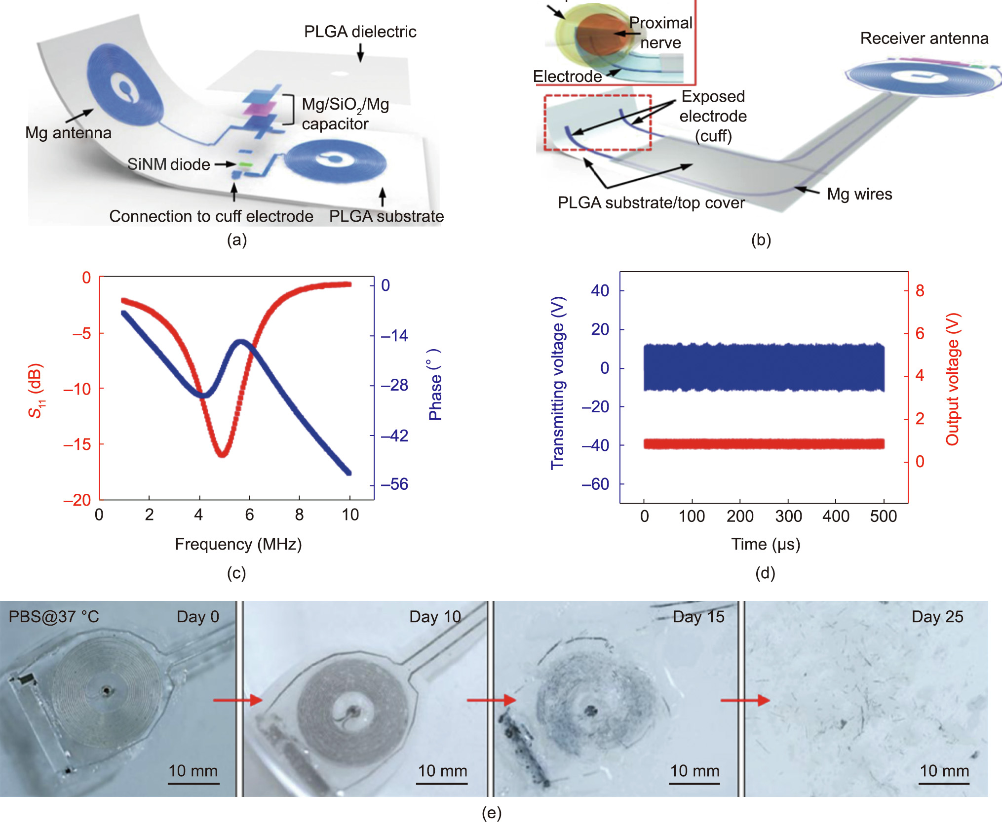
Fig. 12. Bioelectronic device for neuroregenerative stimulation. (a) Schematic of the design. The device encompasses a radio power harvester fabricated from a Mg coil, diode fabricated from 320 nm thick SiNM and 300 nm thick Mg electrode, and Mg/SiO2/Mg capacitor over the PLGA substrate. (b) Illustration of device integration with receiver antenna. (c) Resonant frequency of the stimulator. (d) Output waveforms (red and blue represent the stimulator and transmitter, respectively) when AC (sine wave) is applied to transmission coil. (e) Images representing dissolution of bioresorbable wireless stimulator associated with immersion in phosphate-buffered saline (PBS) (pH 7.4) at 37 °C. Reproduced from Ref. [155] with the permission of Springer Nature, ©2018.
Devising miniaturized bioelectronics for wireless neural stimulation has always been the major driving force behind neuroscience research. Most of the aforementioned bioelectronics for neural stimulation operate at a low frequency and are wirelessly powered using inductive coil systems. Although magnetic fields undergo minimal attenuation while propagating through the body tissues [195], the coil size at a low operating frequency can pose limitations for miniaturizing the overall implant size. Recently, magnetoelectric materials have been explored for wirelessly powering a miniature neural stimulator operating at a wide range of frequencies (Figs. 13(a) and (b)) [196]. These materials are capable of converting magnetic fields into electric voltages and obviate the requirements of an antenna and rectifier. A thin layer of magnetoelectric material generates strain on its interaction with applied magnetic fields owing to the magnetic dipole realignment. It also strains the piezoelectric layer when generating voltages and turning on the LED for optogenetic stimulations (Fig. 13(c)).
A thin stretchable antenna integrated in a wireless optogenetic device has shown potential for wideband RF power harvesting (Fig. 13(d)) [197]. The device achieves optogenetic modulation of the spinal cord and peripheral nervous system. To miniaturize the device, an antenna is fabricated with compact Ti/Au serpentine electrical interconnects and resonates at 2.35 GHz with over a 200 MHz operational bandwidth. The whole circuit is encapsulated with a polyimide (PI) and low modulus silicone elastomer (Fig. 13(e)). The device is excited with at an RF power of ~2 W that is transmitted through the configuration of four external antennas. The RF harvesting unit comprises a rectifier, voltage multiplier, and LEDs (requires 2.7 V to turn on), connected with a stretchable antenna through serpentine electrical interconnects. Miniaturized Schottky diodes and a ceramic chip capacitor are integrated within the rectifier and connected with a voltage multiplier.
《Fig. 13》

Fig. 13. (a) Image of the device on a finger; scale bar: 5 mm. (b) Schematic of the device over a freely moving rat. The inset image shows the transfer of strain from the magnetostrictive layer to the piezoelectric layer for producing voltage across the film. (c) Resonant response of the magnetostrictive layer, representing the maximum produced voltage at an acoustic resonance of 171 kHz. The inset image shows the fabricated stimulator. The right-side inset shows the calculated stress using COMSOL. (d) Schematic of integrated components in the system. (e) (i) Fabricated device (0.7 mm in thickness, 3.8 mm in width, and 6 mm in length) over the fingertip and (ii) its stretchable connection with an LED. PVDF: polyvinylidene fluoride; PZT: lead zirconate titanate. (a)–(c) Reproduced from Ref. [196] with the permission of Elsevier, ©2020; (d) and (e) reproduced from Ref. [197] with the permission of Springer Nature, ©2015.
In Ref. [181], a wirelessly controlled injectable photometric probe is presented for continually recording neural dynamics. The receiving antenna of a probe is wirelessly coupled with an external primary coil using magnetic resonance and fabricated with a seven-turn dual-sided copper coil (quality factor of 23.05) with 100 μm wide traces and 50 μm spacings. It resonates at 13.56 MHz and establishes a wireless communication link with an external antenna that is folded around the experiment enclosure. The incorporation of optogenetics and pharmacology using an optofluidic device has improved neurochemical signal sensing and overcomes the limitations associated with conventional physical tethers. These are inconvenient with respect to insertion into the brain and unsuitable for experimental paradigms that entail subject movements. The concept of programmable pharmacology and optogenetics was recently demonstrated using a soft wireless microfluidic system and encompasses a magnetic loop antenna to establish WPT links with an external primary antenna, thus making the overall system battery-free and miniaturized [198]. A flexible printed circuit board (PCB) platform was used to assemble an antenna with a rectifier and capacitor to tune the resonant frequency to 13.56 MHz. The harvested RF power ranges from 11 to 115 mW.
《10. Conclusions》
10. Conclusions
Bioelectronics are becoming an increasingly common feature of consumer and clinical medical devices and have created tremendous interest within the neuroscience research community owing to their multifunctional capabilities in treating a wide range of ailments. This study reported a comprehensive overview of the recent advances in bioelectronics that are wirelessly controlled and currently deployed clinically. The seminal advantages of using wireless technology for real-time physiological sensing and dynamic control of devices without any wires or catheters are elucidated.
The emphasis of this study is on the antenna systems and associated electronics for establishing reliable and effective power transfer capabilities that are conducive to realizing battery-free and miniaturized devices. The importance of efficient antenna design and wireless communication protocols is highlighted to overcome the challenges associated with transferring data to the external receiver with minimum attenuation through the body tissues. The key features of an antenna, such as its dimensions, operating frequency, radiation characteristics, and in vivo measurements, are discussed. Apart from the antenna, other electronic components, such as a rectifier, power divider, and voltage regulator, are highlighted to explain the overall wireless operation process. This review concludes that wireless technology can effectively reduce the size of a bioelectronic device by making it battery free and can offer promising alternative powering or charging methods. It is also summarized that coil-shaped antenna systems are predominantly utilized for bioelectronics owing to their compact designs and ability to couple with external units via magnetic fields that undergo minimal attenuation through body tissues.
Although bioelectronics have the potential to combat emerging challenges in healthcare, concerted efforts are required from developments in soft and biocompatible materials, low-power electronics, antennas, and signal processing to extend their scope. In this review, we have found that wireless bioelectronics have been mainly explored for brain implants, and very few reports discuss their potential use in drug delivery, GI tract monitoring, and cardiovascular healthcare. Thus, there are still many open opportunities to enhance bioelectric capabilities with wireless control to develop future innovations in the therapeutic treatment of different organs. This review is completed with the help of NLP-based survey and explained in details in Appendix A.
《Compliance with ethics guidelines》
Compliance with ethics guidelines
Ahsan Noor Khan, Young-ok Cha, Henry Giddens, and Yang Hao declare that they have no conflict of interest or financial conflicts to disclose.
《Appendix A. Supplementary data》
Appendix A. Supplementary data
Supplementary data to this article can be found online at https://doi.org/10.1016/j.eng.2021.10.019.


 京公网安备 11010502051620号


