《1. Introduction》
1. Introduction
Rechargeable batteries with high volumetric energy densities that can be charged/discharged at high rates are desirable for electric vehicles (EVs) and other high-power devices [1–5]. While considerable progress has been achieved in the most commercialized lithium-ion batteries, depleted Li resources remain a significant issue for market consideration [6–10]. Na-ion batteries offer an affordable and earth-abundant alternative to Li counterpart [11– 13]; however, the commonly used hard carbon anodes with high-rate features suffer the suboptimal energy densities [14– 16]. Na with a low electrochemical potential and high theoretical capacity is considered a promising anode material [17–21]. However, dendrite growth and loose deposition stacking remain the major barriers impeding the application of Na anodes in engineering, especially at high rates [22–32].
The formation of dendrites on Na anodes stems from uneven ion distribution and electrodeposition [33,34]. An ideal Na deposition at high current densities requires rapidly and evenly distributed Na+ flux. Otherwise, Na+ would prefer to selectively electrodeposite on local sites, causing dendrite or porous stacking growth [35]. During the stripping process, Na ions have to migrate from the interior of the bulk Na anodes into the electrolyte [36,37]. Nevertheless, Na in the dense metal foil primarily diffuses through sluggish lattice diffusion (10–9 cm2 ∙s–1 ) with a high Na+ diffusion barrier [37–41], thus possibly leading to the localized dissolution of metallic Na during the high-rate stripping process, followed by the collapse of local solid electrolyte interphase (SEI) layer, and then triggering dendrite growth in the following plating process [37]. To address the above issues, tactics of introducing ionic transport paths with a low Na+ diffusion barrier is conducive to accelerate the Na diffusion throughout the bulk anodes. Although complex electrodes with mixed ion and electron-conducting scaffolds have been reported in recent studies, commonly using porous structures may result in irreversible electrolyte consumption and low volumetric capacity [25,42–46]. The balance between the fast charge/discharge, dendrite-free deposition, and compact stacking remains challenging.
Here, we introduced ‘‘sodiophilic” Na3Bi penetration into Na anodes to build abundant phase-boundary ion-transport channels. Ion diffusion along the phase boundaries is supposed to enable several orders of magnitude faster than lattice diffusion [41,47–49]. Thus, Na ions quickly extract/insert along the boundaries between Na and Na3Bi phase during stripping and plating processes, thus maintaining the even ion-flux distribution as shown in Fig. 1(a). Moreover, the sodiophilic bismuthide enables uniform and dense Na deposition during cycling, thus aiding high volumetric capacity. The Na3Bi-penetrated Na hybrid anode delivers a high current density of 5 mA∙cm–2 along with a capacity of 5 mA∙h∙cm–2 for over 300 h and ultralong cycle life (over 2800 h) at 2 mA∙cm–2 under 2 mA∙h∙cm–2 . The Na3V2(PO4)3 (NVP)/(Na/Na3Bi) full cell exhibits superior electrochemical performance than those with the bare Na foil anodes.
《2. Results and discussion》
2. Results and discussion
Fig. 1 shows the comparison between Na3Bi-penetrated Na and Na on Cu foil (Na/Cu anode) during initial plating, subsequent stripping, and plating behaviors. During predepositing Na on Cu foil, Na+ flux preferentially deposits at tips because of the convergent electrical field, thus forming non-uniform initial deposition (Fig. 1(b)). The sluggish and uneven Na+ diffusion paths lead to localized dissolution and deposition over cycling in subsequent stripping and plating processes. The resulting cavities and volumetric fluctuations induce continuous destruction and repair of the SEI, thus becoming a potential danger of dendrite growth. Conversely, Na+ flux nuclear homogenously on the Na3Bi framework for the initial plating because of the strong affinity between Na and Na3Bi, thereby filling the inner space of the Na3Bi framework (Fig. 1(a)) to ensure the compactness of Na3Bi-penetrated Nahybrid anode and deliver high volumetric capacity. Correspondingly, Na+ rapidly exits/enters along the boundaries, thus maintaining the stability of the anode interface. Unlike the Na/bulk Na3Bi anode, although because of the sodiophilic nature of the Na3Bi material, bulk Na3Bi can lead to uniform deposition to some certain extent. However, because of the lack of a framework to accommodate metallic Na, it tends to concentrate on the upper part of the anode, which is not conducive to long-term cycle stability (Scheme S1 in Appendix A).
《Fig. 1》
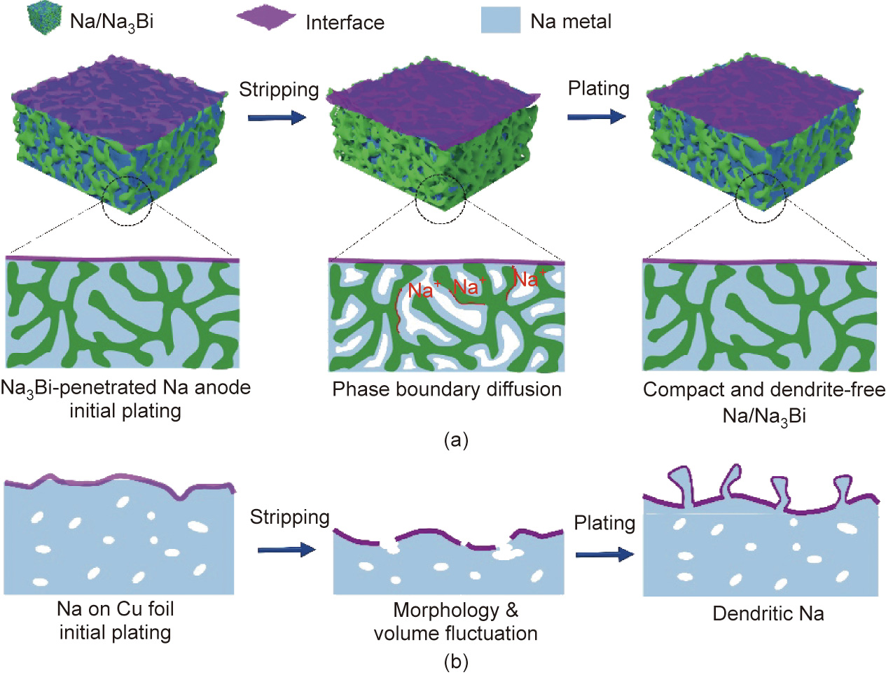
Fig. 1. Schematic for Na stripping/plating in (a) Na3Bi-penetrated Na and (b) Na/Cu anode.
The compact Na anodes with Na3Bi penetration (Na/Na3Bi anode) was developed by electroplating metallic Na into a threedimensional (3D) Na3Bi framework. The Na3Bi framework was evolved from bismuth (Bi) powder through alloying/dealloying processes (Figs. S1 and S2 in Appendix A) [50,51]. Fig. 2(a) shows the scanning electron microscopy (SEM, Nova NanoSEM450, FEI company, USA) image. The Na3Bi framework presents a coral-like structure, and the unique morphology makes it easier for Na+ to be deposited uniformly (Fig. 2(b), as described later). In a high-resolution transmission electron microscope (HRTEM, JEM-2100, JEOL, Japan) image (Fig. S3 in Appendix A), the interplanar distance of 4.04 Å (1 Å = 10–10 m) corresponded to (101) crystal planes of Na3Bi. After electroplating, metallic Na is completely embedded in the Na3Bi framework to form the Na3Bi-penetrated Na anodes, as shown in Figs. 2(c) and (d). The prominent peaks in the X-ray diffraction (XRD, D8 Advance, Bruker, Germany) spectra are well matched to the characteristic Na3Bi and Na, confirming that the presence of Na does not affect the composition of the framework (Fig. S4 in Appendix A). We set up two control groups, namely, the Na/bulk Na3Bi (i.e., without the alloying/dealloying process and framework structure) and Na/Cu anodes, to compare the superiority of the Na/Na3Bi anode. Furthermore, the difference between the control groups is described in detail in Appendix A.
《Fig. 2》
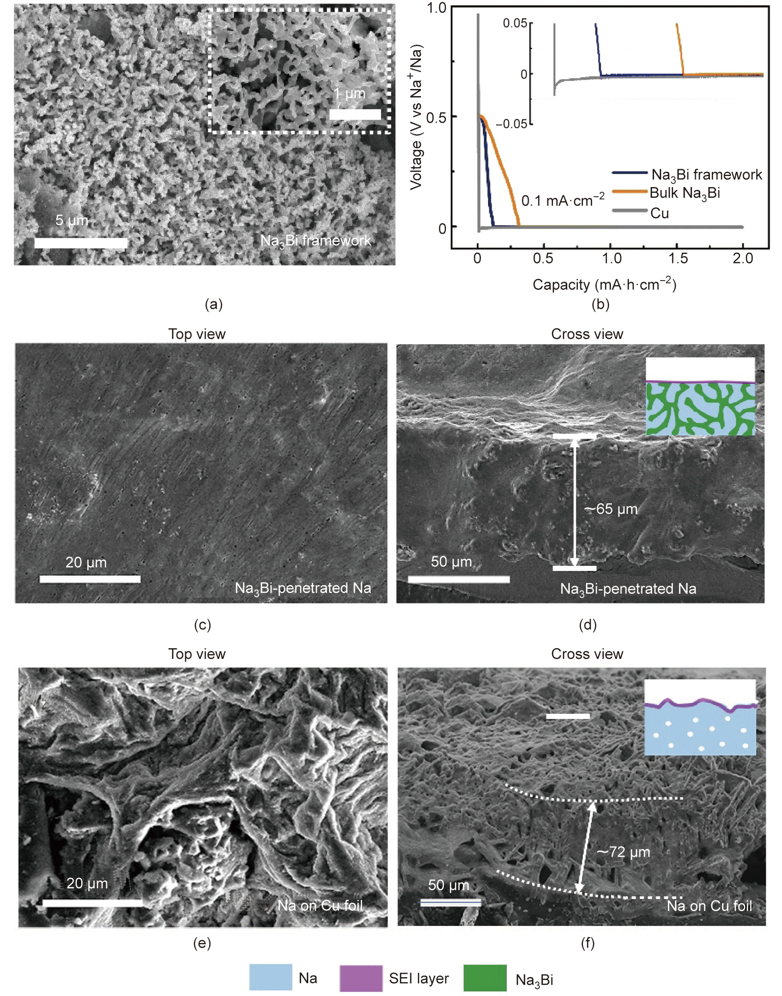
Fig. 2. (a) SEM images of the Na3Bi framework before penetrating in Na anode. (b) Na plating curves on three matrix samples at 0.1 mA∙cm–2 , showing overpotential of Na nucleation. SEM images of top and cross view of (c, d) compact Na anodes with Na3Bi penetration and (e, f) Na on Cu foil. The insets schematically elucidate the initial plating morphology.
The ‘‘sodiophilic” Na3Bi framework leads to uniform local ion distribution and delivers homogenous inner-space Na+ plating. The energy to overcome the nucleation barrier between Na and substrates is remarked as a nucleation overpotential. As shown in Figs. 2(b) and S5 in Appendix A, the overpotential on Cu is ~19 mV at 0.1 mA∙cm–2 and 20 mV at 1 mA∙cm–2 , whereas Na3Bi framework and bulk Na3Bi show an extremely small overpotential (below 4 mV) at the same current density. Differences became apparent with increase in current (Fig. S6 in Appendix A). Thus, both bulk Na3Bi and Na3Bi framework samples effectively reduce the nucleation overpotential, thus confirming the sodiophilic nature of Na3Bi. The same conclusion could be drawn in the phase diagram where Na–Bi alloy exists, and there is no solubility for Na–Cu at room temperature (Fig. S7 in Appendix A), confirming that lower nucleation barriers are present on Na3Bi [52].
Uniform and compact deposition of Na on Na3Bi could be visually observed in SEM images. As shown in Fig. S8 in Appendix A, Na surrounds and covers the framework with even distribution and fills the original Na3Bi framework with the increasing initial plating capacity increases (from 3 to 5 mA∙h∙cm–2 ). Top and cross-sectional SEM images show a smooth surface and compact cross-section at 8 mA∙h∙cm–2 of capacity (Figs. 2(c) and (d)). Moreover, the corresponding energy dispersive X-ray spectrometer (EDX, Model 550i, IXRF, USA) mapping intuitively presents the uniform deposition (Figs. S9 and S10 in Appendix A). Consequently, the dense electrode structure demonstrates the close volumetric capacity to the theoretical value of bulk Na with nearly the maximum sodium capacity this framework could withstand. However, mossy and walnut-like Na could be observed on Na plating on Cu foil, which confirms the formation of dendrite growth after nucleating Na on the top of the Cu foil. Furthermore, uneven deposition results in a porous and loose structure (Figs. 2(e) and (f)), which is not conducive to subsequent anode long-term durability performance. As for bulk Na3Bi, the deposition of Na is still nonuniform (Fig. S11 in Appendix A), confirming the importance of the penetrated sodiophilic frameworks to the uniform and dense deposition. Based on the above evidence, we demonstrated that the ‘‘sodiophilic” Na3Bi framework is prone to induce uniform local ion distribution, thereby delivering homogenous the inner-space Na+ plating and suppressing volume fluctuations.
In addition to the even nucleation, the ionic diffusion barrier of pure Na and Na3Bi was studied by using density-functional theory(DFT) calculation. By equivalent adsorption sites, the diffusion barrier of Na+ in all directions can be calculated [53,54]. Figs. 3(a) and (b) show the minimum energy path for Na diffusion on Na and Na3Bi surfaces, and Figs. 3(c) and (d) show Na diffusion along with the minimum energy path among different adsorption sites. We also compared the Na+ adsorption energy on different adsorption sites (Figs. 3(e), S12, and Table S1 in Appendix A). The maximum Na+ adsorption energy of pure Na and Na3Bi materials are –1.04 and –1.44 eV (1 eV = 1.602176 × 10⁻¹⁹ J), respectively. The reduced adsorption energy of Na+ on Na3Bi indicates that Na+ is inclined to deposit on Na3Bi, thus ensuring the uniform deposition of metallic Na on the Na3Bi framework. The Na+ diffusion barrier of Na3Bi(110) is 0.14 eV; however, that of pure Na(100) is 0.27 eV (Fig. 3(e)). The rapid Na+ transport on Na3Bi(110) surface ensures phase boundaries between metallic Na and Na3Bi with high Na+ migration. For metallic Na, the 0.27 eV of Na+ diffusion barrier guides one-dimensional growth pattern to form Na dendrites (Fig. 3(e)). Consequently, 3D boundary diffusion paths are distributed in the entire anode, as shown in Fig. 3(f). Moreover, the diffusion coefficient (D) and corresponding ionic conductivity of Na+ in the Na3Bi bulk phase were calculated by galvanostatic intermittent titration technique (GITT) test are 7 × 10⁻⁸ cm2 ∙s–1 and 9.8 × 10⁻⁴ S∙m–1 , respectively (Fig. S13 in Appendix A). The high Na+ diffusion coefficient indicates that Na3Bi can withstand a part of Na+ transportation. As shown in Fig. S14 in Appendix A, the GITT curves of Na/Na3Bi||Na/Na3Bi anode delivers lower overpotential compared to that of Na||Na anode, thus showing faster mass transfer kinetics of the Na/Na3Bi electrode.
《Fig. 3》

Fig. 3. The minimum energy path for Na diffusion on (a) Na and (b) Na3Bi surfaces. Green and purple balls represent Na and Bi atoms. The energy barrier of Na diffusion along with the minimum energy path on (c) Na and (d) Na3Bi surfaces. Red ball stands for the diffusion Na. (e) Comparison of the energy barrier of Na diffusion and adsorption energies on Na and Na3Bi surfaces. (f) Schematic of 3D boundary diffusion path in Na/Na3Bi anode.
Electrochemical deposition/dissolution behaviors were further studied, and the top and cross-section of surface morphology were characterized (Figs. 4 and S15 in Appendix A). We notice an interesting phenomenon that no matter how the capacity of Na/Na3Bi anode changes during plating or stripping, the anode surface morphology always remains uniform and flat. The comparison of SEM images between Na/Na3Bi and Na/Cu anode with plating capacity of 3 and 5 mA∙h∙cm–2 clearly indicate that Na/Cu anode is accompanied by uneven deposition and dendrites formation (Figs. 4(a)– (d)). As shown in Figs. 4(e)–(j), theoretically, Na3Bi could be gradually exposed with sodium capacity decreasing; however, the surface still maintains a relatively flat morphology, which indicates that the Na stripping process is entirely carried out on the Na/ Na3Bi anode. In this manner, the integrity of the SEI formed on the surface is preserved and gradually stabilizes during subsequent plating and stripping. Cycled-anodes were disassembled and replaced in carbonate electrolyte containing specific Cl element to further confirm the stripping/deposition behaviors of bare Na along with Na/Na3Bi anode. As shown in Fig. S16 in Appendix A, EDX elemental exhibits the strong Cl signal is distributed over the bare Na foil and the content is more than 3%, indicating the permeation of electrolyte into the interior of the anode. However, Na3Bi-penetrated Na anodes maintain their dense structure with the Cl element’s weak signal on the cross-section. Consequently, the SEI layer of Na/Na3Bi anode remains stable, preventing the simultaneous permeation of electrolytes [44]. Theoretical volume change of ‘‘hostless” Na could reach 200% in the corresponding process (Fig. S17 in Appendix A); however, Na3Bi-penetrated Na anodes with different sodium capacities could almost maintain the same thickness, conducive to stability.
《Fig. 4》

Fig. 4. Investigation of sodium plating/stripping process of Na/Na3Bi and Na/Cu anode. Top view SEM images between (a, b) Na/Na3Bi and (c, d) Na/Cu anode during plating process with 3 and 5 mA∙h∙cm–2 . (e–j) Top and cross view SEM images of Na/Na3Bi anode during stripping process with (e, h) 8, (f, i) 5, and (g, j) 3 mA∙h∙cm–2 capacity. The inset pictures schematically elucidate the presence of sodium inside the anode.
The possible explanation for the flat surface is that theoretically, the metal holes during the stripping process would be left at the interface between Na and the SEI layer, which tend to submerge into the bulk of Na by diffusion. Unfortunately, lattice diffusion delivers a severe situation to atomic migration and is followed by poor Na diffusivity: The diffusivity of Na atoms in the Na metal possesses a low value of 10–9 cm2 ∙s–1 (25 °C) [38]. Consequently, holes accumulate at the sodium/SEI interface and lead to the concentration of large cavities when the rate of Na+ extraction is higher than that of holes submergence [37], which is not beneficial for the stability of the SEI layer [36]. As for the Na3Bi-penetrated Na anodes, the Na and Na3Bi boundaries enable fast Na+ diffusion such that the Na vacancies generating in the surface layer can be quickly filled to maintain the stability of the SEI layer and anode. Consequently, the stripping process can mobilize the Na source and help prevent SEI changes caused by the run-off of the surface sodium. As a result, the embedded Na is protected from exposure to the electrolyte, which causes low coulombic efficiency (CE) and contributes to the electrode’s long-life cycling durability.
CE is an important indicator to investigate the durability of anodes [55]. The CE measurement was performed with three working electrodes (Cu foil, bulk Na3Bi, and Na3Bi framework) from the current densities of 2–5 mA∙cm–2 with capacities of from 2 to 5 mA∙h∙cm–2 (Figs. 5(a), 5(b), and S18 in Appendix A). Over the 900 cycles, CE of Na3Bi could reach 99.78% at 2 mA∙cm–2 and 2 mA∙h∙cm–2 , indicating SEI stability; however, Na deposition/stripping on the bulk Na3Bi and Cu foil samples exhibit lower CE with high fluctuation (Fig. 5(a)). The instability of SEI could be reflected by the low CE values on Cu foil and bulk Na3Bi, while the large fluctuation is attributed to the formation of dead Na and the consumption of electrolytes. The CE of Na3Bi framework anode reaches 97.25% over 300 cycles when the capacity is 4 mA∙h∙cm–2 . Similar CE values and high retention exist for other current density and plating/stripping capacity (Fig. S18). The CE of Na/Na3Bi anode in this study is higher than that of scaffoldconstructing works and equal to that of artificial SEI-constructing works (Fig. S19 and Table S2 in Appendix A).
The nature of the interface between electrolyte components and anodes can be reflected by the Tafel plot [46,56]. Mass transfer dominants current density in high overpotential areas. The higher exchange current density (1.2 compared with 0.058 mA∙cm–2 ) indicates that the Na/Na3Bi anode delivers a faster mass transfer process than that of Na foil (Fig. 5(c)). Electrochemical impedance spectroscopy (EIS, VMP3, Bio-Logic, France) is an effective method to research interface changes between electrolyte components and anodes before and after 50 cycles among Na/Cu anode, Na/bulk Na3Bi anode, and Na/Na3Bi anode (Figs. 5(d) and S20 in Appendix A). Before cycling, the interfacial impedances of Na/Na3Bi, Na/bulk Na3Bi, and Na/Cu anodes are ~2, ~3, and ~25 Ω, respectively. After repetitive cycling, Na/Cu anode showed augmented interfacial impedances to 55 Ω, which is commonly observed because of the SEI accumulation and excessive dead Na build-up; conversely, benefited from the fast Na+ diffusion and a stable interface, the resistance of Na/Na3Bi anode maintained low and stable (~1.5 Ω).
《Fig. 5》

Fig. 5. The CE of Na deposition of three samples for (a) 2 mA∙h∙cm–2 and 2 mA∙cm–2 , and (b) 4 mA∙h∙cm–2 and 4 mA∙cm–2 . (c) Tafel plots obtained from cyclic voltammetry measurements. (d) Nyquist plot with Na/Cu electrode, Na/bulk Na3Bi anode, and Na/Na3Bi anode before and after 50 cycles.
The galvanostatic cycling durability for Na/Cu anode, Na/bulk Na3Bi anode and Na/Na3Bi anode was investigated. Fig. 6(a) shows the voltage profiles for the three anodes cycled for 2 mA∙cm–2 along with 2 mA∙h∙cm–2 . Note that the Na/Na3Bi anode exhibits low overpotential (~10 mV) with long-life stability for over 2800 h, while the other two anodes fail in 400 h. Moreover, Na/Na3Bi anode displays ~35.5 mV of low overpotentials after 300 h at a current density of 5 mA∙cm–2 with 5 mA∙h∙cm–2 , which is superior to those of Na/Cu and Na/bulk Na3Bi anode, affirming the excellent stability of Na3Bi at high rates and with deep plating/stripping behaviors (Fig. 6(b)). Top and cross view SEM images (Figs. 6(c)–(f) and S21 in Appendix A) are obtained to study the derivation of the cycling durability of Na/Na3Bi anode: Smooth surface morphology and compact Na3Bi-penetrated structure occur during the whole cycling, whereas increasingly uneven deposition and gradually loose structure cause the failure of Na/Cu anode in a short time. X-ray photoelectron spectroscopy (XPS, ESCALAB 250Xi, Thermo Scientific, USA) was also used to examine the SEI formed in the cycled anode (Fig. S22 in Appendix A). The C 1s spectrum can be fitted using three peaks with the binding energies of 288.2 eV (RCH2ONa), 286.0 eV (C–O), and 284.8 eV (C–C and C–H), whereas the O 1s spectrum shows a corresponding peak at 535.5 eV (C–O), both of which are consistent with sodium alkoxides being the main reduction product of diglyme [57,58]. The O 1s spectrum also shows a peak at 530.9 eV (Na–O). Combining these analyses with the Na 1s spectrum, we deduce that the Na 1s feature at 1071.0 eV comprises two overlapping peaks (Na–O and Na–F), which are consistent with the tabulated values for Na2O and NaF. These results indicate the formation of Na2O and NaOH (532.8 eV) as the reaction product of Na metal with trace amounts of O2 and H2O in the Ar-filled glovebox (< 0.5 ppm) and NaF as the main reduction product of NaPF6 [57–59]. Overall, we see that the top surface of the SEI contained both organic (RCH2ONa) and inorganic (Na2O and NaF) components. Note that the electrochemical performance of Na/bulk Na3Bi anode is not significantly optimized, which indirectly affirms the important role of phase-boundary diffusion in guiding homogeneous and rapid ion transport. Furthermore, the Na3Bi framework remains stable based on SEM images (Fig. S23 in Appendix A) because the plating/stripping potential (±50 mV) of Na is far away from the phase change potential of Na3Bi (0.7 and 0.5 V for alloying potentials and 0.6 and 0.75 V for de-alloying potentials), thus ensuring the structure’s stability. The advantages of the overpotential and cycle life are also reflected in other current density and fixed real capacity conditions (Fig. S24 in Appendix A). Moreover, the Na/Na3Bi anode delivers good rate performance (Fig. 6(g)), in which small polarization (~100 mV) can still be obtained even at a relatively high current density (10 mA∙cm–2 ). It is essential to explore the performance of electrodes at low temperatures because ion-diffusion kinetics is closely related to the operating temperature, and demand for high-energy batteries that can operate at low-temperature conditions continues to grow. The cycling performance of the Na/Na3Bi and Na/Cu anodes at 2 mA∙cm–2 and 2 mA∙h∙cm–2 at 278 K is shown in Fig. 6(h), and a Na/Na3Bi anode with lower overpotential (~100 mV) and stable cycling over 300 h is obtained. Conversely, Na/Cu anode fails quickly with 200–300 mV of overpotential, signifying that the low diffusion barrier of phase boundaries between Na and Na3Bi enable effective ion transportation even at low temperature.
To assess the electrochemical performance of three different anodes in full cells, the Na/Na3Bi and bare Na anodes are coupled with NVP as the cathode in 1 mol∙L–1 NaClO4 in ethylene carbonate (EC)/diethyl carbonate (DEC) respectively. Due to the fast ion transport and uniform deposition/stripping of Na/Na3Bi anode, high-energy-density Na–metal batteries are obtained. NVP/(Na/ Na3Bi) cell shows good capability retention of 93.8% with current densities of 0.2 to 2 C (Fig. S25 in Appendix A), which is much higher than Na anodes. As current densities increasing, the polarization of the charge/discharge plateaus slowly increases (Fig. S26 in Appendix A). Moreover, NVP/(Na/Na3Bi) cell delivers excellent cycling performance for 72 mA∙h∙g–1 of reversible capacity at 1 C and over 1000 cycles, and the capacity retention is 91.1% (Figs. S25 and S26). During charging, the average CE of NVP/(Na/ Na3Bi) cell at 1 C could achieve 98.35% and maintains durable cycling performance.
《Fig. 6》

Fig. 6. Galvanostatic cycling performance of different anodes for (a) 2 mA∙h∙cm–2 and 2 mA∙cm–2 m, and (b) 5 mA∙h∙cm–2 and 5 mA∙cm–2 . Top and cross view SEM images of (c, d) Na3Bi-penetrated Na anode and (e, f) Na/Cu anode after galvanostatic cycling. (g) Rate performance of the Na/Na3Bi anode. (h) Low temperature (278 K) cycling performance of Na/Na3Bi and Na/Cu anode.
《3. Conclusions》
3. Conclusions
In this work, bulk Na–metal anodes with sodiophilic Na3Bi penetration, which holds even nucleation and uniform and dense Na deposition, could deliver a high rate, a long cycle life, and a high volumetric capacity. As a result, abundant Na/Na3Bi phase boundaries, which proved to enable Na+ diffusion several orders of magnitude faster than lattice diffusion, ensure sufficient and rapid Na+ migration taking place upon plating and stripping. During initial deposition, the exposed ‘‘sodiophilic” Na3Bi framework induces uniform local ion distribution, thereby delivering homogenous inner-space Na+ plating and suppressing volume fluctuations. In subsequent stripping and plating processes, Na+ rapidly exits and enters along the boundaries of Na and Na3Bi phase, maintaining the stability of the anode/electrolyte interface. Furthermore, the obtained anode delivers superior cycling and rate performances coupled with the NVP cathodes.
《Acknowledgments》
Acknowledgments
This work was supported by the National Natural Science Foundation of China (21938005 and 21776197) and Key Laboratory of Coal Science and Technology, Education Ministry and Shanxi Province, Taiyuan University of Technology.
《Compliance with ethics guidelines》
Compliance with ethics guidelines
Wanyu Zhao, Min Guo, Zhijun Zuo, Xiaoli Zhao, Huanglin Dou, Yijie Zhang, Shiying Li, Zichen Wu, Yayun Shi, Zifeng Ma, and Xiaowei Yang declare that they have no conflict of interest or financial conflicts to disclose.
《Appendix A. Supplementary data》
Appendix A. Supplementary data
Supplementary data to this article can be found online at https://doi.org/10.1016/j.eng.2021.08.028.


 京公网安备 11010502051620号


