
《1. Introduction》
1. Introduction
The term ‘‘metamaterial” was originally exclusively used to refer to engineered materials that manipulated electromagnetic waves in the field of electromagnetics and photonics [1–5]. Recently, however, the term has been extended to materials that manipulate acoustic and elastic waves and have been found to exhibit exotic and superior mechanical properties—materials that are now called ‘‘mechanical metamaterials.” Auxetics, which are intentionally designed materials with a negative Poisson’s ratio (NPR, υ < 0), were one of the earliest mechanical metamaterials [6]. Mechanical metamaterials are a class of artificial materials that exhibit exotic mechanical properties not found in nature. Their unique properties are primarily derived from the topology of specifically designed representative units, rather than from the inherent properties of their constituent materials. In fact, a mechanical metamaterial is often built by periodically tessellating a representative unit, also known as a ‘‘unit cell.” Through the architectural design of the unit cell, various unusual mechanical properties—such as an NPR [6,7], high stiffness-to-weight ratio [8–10], vanishing shear modulus [11–13], negative stiffness [14,15], and negative compressibility [16]—can be attained. Because of their extraordinary mechanical properties, mechanical metamaterials have been studied for a broad range of applications, ranging from auxetic textiles [17] and auxetic nails [18] to smart filters [19], vibration dampers [14,20,21], and protective devices [16]. These properties, however, often require complex threedimensional (3D) topologies and small feature sizes, making it a challenge to be realized via conventional manufacturing techniques.
Additive manufacturing (AM), as a rapidly evolving manufacturing technology, offers a high degree of control over precision, geometry, and feature sizes; thus, it represents a viable pathway to manufacture mechanical metamaterials. Despite numerous published studies on additive manufactured metamaterials, these technologies are still at their early stage and present various technical challenges to be overcome. Hence, it is essential to understand the topologies and their associated AM technologies from past to present, and to identify new opportunities to improve the synergies between metamaterial design and manufacturing.
The combination of metamaterials and AM is a transformative topic that can lead to the next evolution in mechanical metamaterials, and many relevant studies have been published recently. There are several excellent review papers on mechanical metamaterials; however, these studies focus on lightweight lattices [22], auxetics [23–25], fabrication [26], design [27–29], and applications [30,31]. Therefore, there is a need to specifically provide a comprehensive review of mechanical metamaterials in terms of the relationship between structures and properties, and recent progress in advanced AM techniques regarding mechanical metamaterials. This review addresses this need, while also summarizing the existing challenges and future opportunities that are critical in allowing this promising field to flourish. Although a broad array of metamaterial properties exist, including ultra-lightness, ultrahigh strength and stiffness, NPRs, negative stiffness, nonlinear behavior, and pentamode materials, most are realized through designed twodimensional (2D) or 3D architectures comprising repeating unit cells. Without loss of generality, we will focus on lightweight materials (i.e., stiff and strong materials) and auxetic materials, which have been rapidly developed and applied in the past 5 years. Accordingly, we will discuss emerging AM technologies that are particularly suitable for realizing these classes of novel metamaterials.
《2. Architectural design of mechanical metamaterials》
2. Architectural design of mechanical metamaterials
This section is devoted to a fundamental understanding of pastto-present mechanical metamaterials and is divided into two subsections. The first subsection examines metamaterials in terms of Young’s modulus and strength (i.e., stiff, strong, and lightweight metamaterials), while the second subsection discusses auxetic metamaterials (i.e., metamaterials with an NPR).
《2.1. Young’s modulus and strength》
2.1. Young’s modulus and strength
For decades, scientists and engineers have architected many new lightweight materials with superior Young’s modulus and strength by controlling the phase topology of biphasic materials or cellular materials—that is, materials in which one phase is the void and the other phase is the solid constituent material. Such properties are not achievable using monolithic bulk materials as, for example, bulk metals are stiff and strong but heavy. In the case of cellular material, its Young’s modulus E, elastic buckling strength σel, and non-buckling strength σ—that is, the yield strength if the constituent material is ductile or the fracture strength if the constituent material is brittle—generally follow a power-law scaling to the relative density  [32,33], where
  is the ratio of the cellular material’s density to the density of the constituent material of which the cellular material is made, and α is a constant dictated by the topology of the cellular material. Here, α = 1 [34,35] if the topology is ideally stretching dominated (i.e., deforms majorly through stretching). Or, for some stochastic topologies such as aerogels, for example, α = 2 [34,35] or 3 [36– 39] for E, and α = 1.5 [34,35] for σ if the topology is ideally bending dominated (i.e., deforms majorly through bending). Most topologies fall between these two extremes. It is notable that α = 2 [34,35] for σel, regardless of the topology. It is evident from the power-law scaling that the E and σ of stretching-dominated topologies are much higher than those of bending-dominated topologies at ultralow . It is evident from these scaling relationships that stretching-dominated topologies are a more attractive choice than bending-dominated topologies for lightweight applications. The typical 3D topologies classified by their elemental structure features are summarized in Fig. 1 [8–10,35,40–43]. In the subsequent subsections, which categorize topologies into beambased, plate-based, or minimal surface-based, we discuss the mechanics of several stiff and strong stretching-dominated topologies and identify various bending-dominated topologies.
《Fig. 1》

Fig. 1. Illustration of 3D (a) beam-based, (b) plate-based, and (c) minimal surface-based topologies. Reproduced from Refs. [8–10,35,40–43] with permission.
2.1.1. Beam-based topologies
Classical beam-based topologies are the most widely used, with well-documented studies and design principles [44–46]. They consist of rods with identical dimensions (e.g., identical radius and rod length, in the case of cylindrical rods) connected through shared nodes. Their mechanical efficiency depends on the nodal connectivity of the topologies, governed by Maxwell’s necessary (not sufficient) condition of rigidity (stretching domination) [44]:
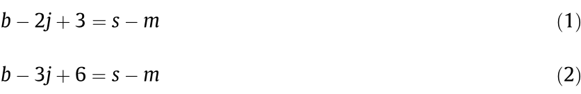
where b is the number of struts, j is the number of connecting nodes, s is the number of self-stress states, and m is the number of mechanisms. From Eqs. (1) and (2), the necessary minimal number of beams per node for stretching domination is four in 2D and six in 3D. If the beams are slender (low ), they can be ideally determined as stretching dominated  or bending dominated
  as discussed in the beginning of Section 2.1. If the beams are stocky (high ), the nodal geometry plays an important role, and the mechanical efficiency can no longer be described by the classical scaling law [47,48].
Representative stretching-dominated topologies (Fig. 1(a)) include the octet truss (anisotropic) [8,9,49,50], isotropic truss (isotropic) [8], cube (anisotropic) [40,51], face-diagonal cube (anisotropic) [40], body-centered cube (anisotropic) [40], truncated cube (anisotropic) [40], octahedron (anisotropic) [40,52], and void octet (anisotropic) [40]. Representative bending-dominated topologies (Fig. 1(a)) include ideal open-cell foam (anisotropic) [32,35], Kelvin foam (anisotropic) [9,53], and truncated octahedron (anisotropic) [40]. It should be noted that none of these topologies reach the Hashin–Shtrikman (H–S) bound for 3D isotropic cellular materials [54]. In fact, it has been shown theoretically that only closed-cell (i.e., the void phase is not interconnected) plate-like topologies can achieve the bound [55].
2.1.2. Plate-based topologies
In contrast to beam-based topologies, plate-based topologies have the potential to attain maximal isotropic stiffness. Platebased topologies consist of sheets of thin angled plates that connect through the plate edges, usually forming a closed-cell network. Each plate develops membrane stress under deformation along multiple in-plane directions, thereby providing multiaxial stiffness, while each beam of beam-based topologies can only support axial forces [32,56,57]. At low relative density, the membrane stress developed in these closed-cell plates can become the dominant contribution to the macroscopic stiffness, leading to stretching-dominated behavior (linear dependence of E and σ on ) [35,58]. As such, the Young’s modulus E of an optimal closedcell plate-based topology can be as much as three times greater than that of an equivalent optimal beam-based topology [55]. For example, octet foams are about three times stiffer than octet trusses at the same low relative density [8].
In fact, several stretching-dominated plate-based topologies— such as 2D triangular and kagome honeycombs [34,59], 3D cubic + octet foams [8,42,60], and n-fold symmetry plate lattices [41] (Fig. 1(b))—have been identified that achieve the H–S upper bound of moduli for 2D [61] and 3D [54] isotropic cellular materials, as is briefly summarized below:
(1) The 2D H–S upper bound:
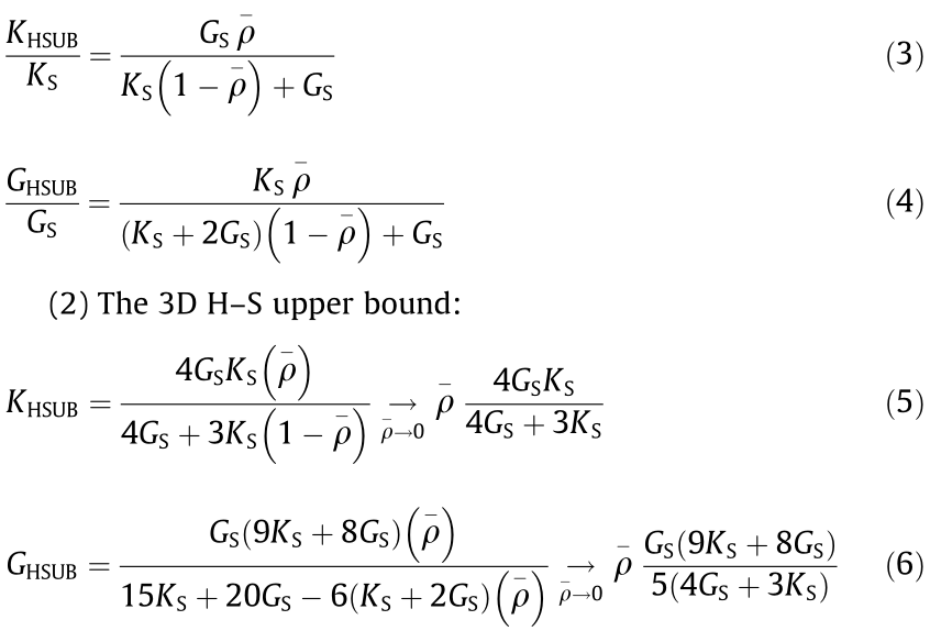
where K and G are the bulk modulus and shear modulus, respectively; and the subscripts ‘‘HSUB” and ‘‘S” represent the H–S upper bound and the constituent material property, respectively. Other stretching-dominated plate-based topologies (shown in Fig. 1(b) and Fig. 2) are N-kagome honeycombs (2D isotropic) [62], square honeycombs (2D anisotropic) [63,64], statically indeterminate (SI)-square honeycombs (2D anisotropic) [62], cubic foams (3D anisotropic) [8,58], octet foams (3D anisotropic) [8,42], and tetrakaidecahedron (3D isotropic) [42,58,65]. Some bendingdominated topologies (Fig. 2) include hexagonal honeycombs (2D isotropic) [34], Voronoi honeycombs (2D isotropic) [66–68], and diamond honeycombs (2D anisotropic) [63,64]. It is notable that, similar to the counterpart beam-based topologies, at large , the bending deformation of the enlarged joints and nodes between neighboring plates contributes significantly to the load-carrying capacity, resulting in nonlinear dependence of E and σ on .
《Fig. 2》
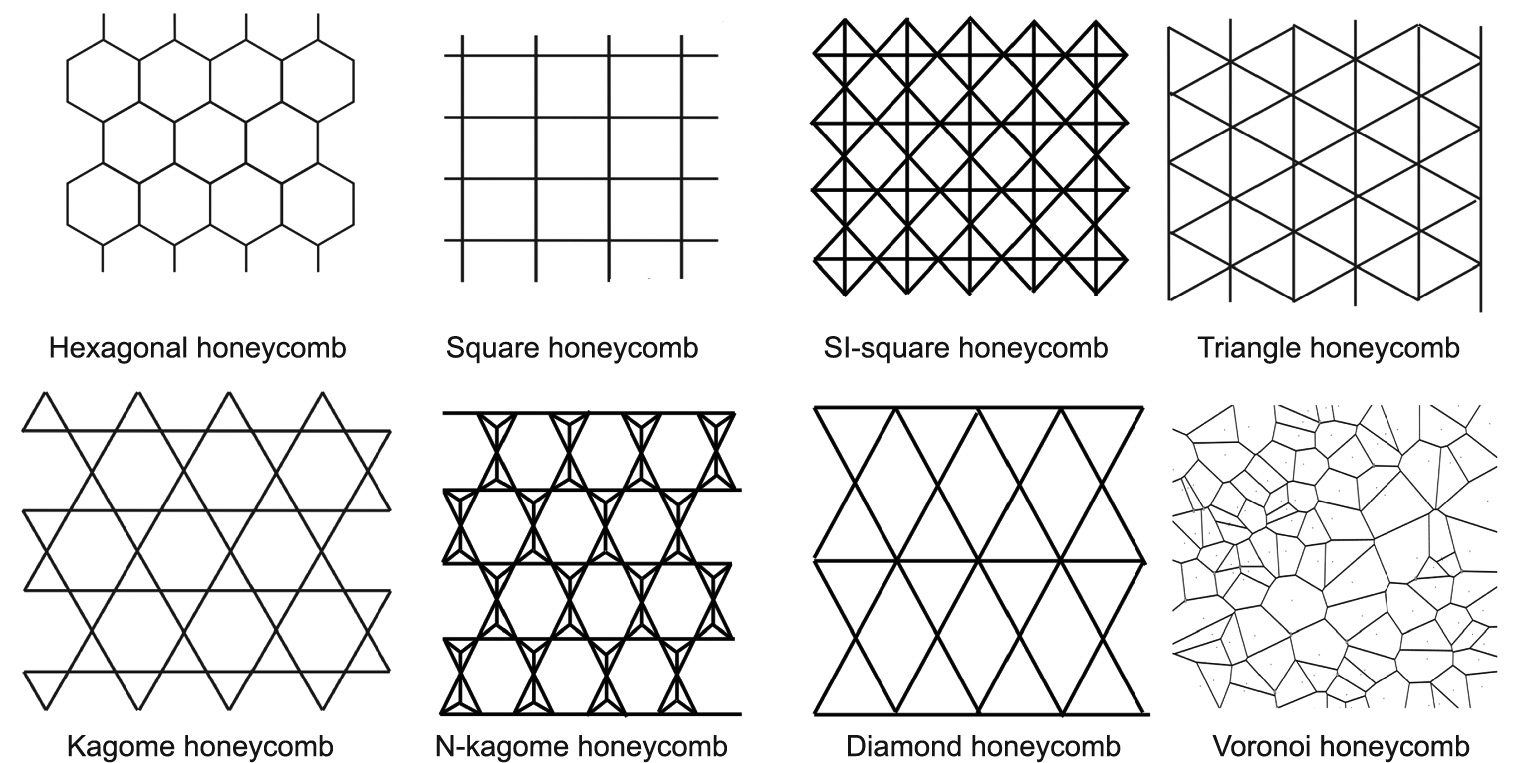
Fig. 2. Illustration of 2D honeycomb topologies. Reproduced from Refs. [34,62,63,66] with permission.
2.1.3. Minimal surface-based topologies
Minimal surface-based topologies consist of thin, continuous, and smooth shells on which the mean curvatures (i.e., the average of the principal curvatures, (κ1+κ2)/2) are zero and the Gaussian curvatures (i.e., the multiplication of the principal curvatures, κ1 ·κ2) are readily negative everywhere. Due to the very uniform double curvatures, bending of these smooth thin shells necessarily induces in-plane straining, which leads to a stretching-like behavior [69]. In addition, unlike beam-based and plate-based topologies, minimal surface-based topologies do not have any defined nodal geometry, which effectively eliminates stress concentration and reduces the fractures that are encountered around nodal connections in beam-based and plate-based structures [70–73].
A very typical example of these minimal surface-based topologies is a class of triply periodic minimal surfaces (TPMSs, with repeating unit cells in three dimensions) that have cubic symmetry. In general, TPMSs can be approximated by level-set equations Φ. For example, the level-set equations of four common TPMSs— Schwarz primitive (P), Schwarz gyroid (G), Schwarz diamond (D), and I-graph–wrapped package (I-WP) given below [74–77]↑ :

where x, y, and z, bounded by [0, 2π] for a single unit cell, are the nodal coordinates of points on the approximated TPMSs. The desired relative density of the topologies is then controlled by the volume of the solid region. For low (thin shells), all these TPMSs (shown in Fig. 1(c))—that is, primitive (anisotropic) [43,78– 80], gyroid (anisotropic) [43,81,82], I-WP [43,79,83], neovius [43,79], Fischer–Koch S (isotropic) [43], and diamond [81,82]—are stretching dominated.
↑ For more TPMS level-set equations and computer-aided design (CAD) files, please see ‘‘Minisurf—A minimal surface generator for finite element modeling and additive manufacturing” in Refs. [75,76].
Spinodal shells (Fig. 1(c)) are another type of minimal surfacebased topology [10]; they are derived from the interface geometry of a 50%/50% ratio of dense bicontinuous liquids or solids undergoing spinodal decomposition [84,85]. Although spinodal decomposition has been known for decades, spinodal shells were only recently discovered and studied in the mechanics community. They have been shown to possess minimal surface characteristics and to exhibit isotropic stretching-dominated behavior, all while in a stochastic topology [10,86,87]. Furthermore, unlike the beam-based, plate-based, and TMPS topologies discussed earlier, spinodal shells are potentially very scalable, which is useful for exploiting the size-effect strengthening of the constituent material via self-assembly processes, followed by postprocessing such as coating at the macroscale [88–90].
To conclude this section, we plot the available stiffness and yield strength data of all the topologies discussed in Section 2.1 versus the relative density in Fig. 3 [8–10,34,40–43,49,51,52,62, 64,68,78,80,81,91,92]. For lightweight materials design, specific strength and specific stiffness are two of the most important parameters to evaluate lightweight materials; therefore, a specific strength versus specific stiffness property chart comparing different topologies is plotted in Fig. 4 [9,38,42,49,52,73,77,81,93]. Beam-based structures, as classic lightweight designs, have been widely used in practical applications. Recently, an increasing number of micro-beam-based structures, especially nano-lattices, have been fabricated due to advances in high-precision AM techniques. These nano-lattices exhibit exceptional mechanical performance at extremely low densities; their properties, which include ultrahigh stiffness [9], strength [93], and damage tolerance [94], expand the limits of the accessible materials-properties space. Although these beam-based structures can achieve high mechanical efficiency, these structures are fundamentally incapable of achieving the theoretical upper bounds for isotropic elasticity (i.e., the H–S and Suquet–Ponte Castaneda (S–PC) upper bound [51,91,92]).
《Fig. 3》
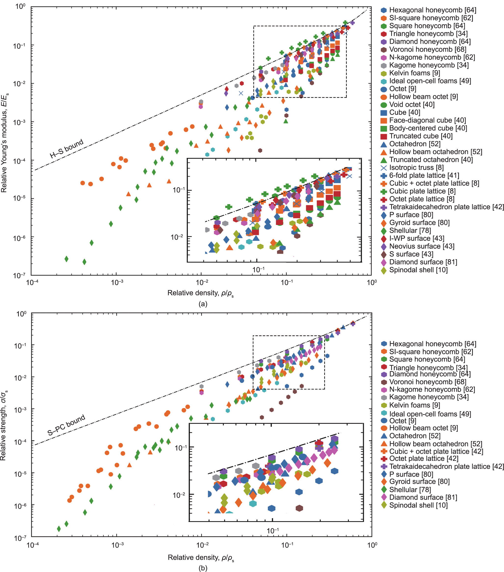
Fig. 3. Comparison of (a) relative Young’s modulus and (b) relative yield strength of the discussed beam-based, plate-based, and minimal surface-based topologies at various relative densities. H–S [51] and S–PC [91,92] upper bounds are also plotted against the relative density.
《Fig. 4》
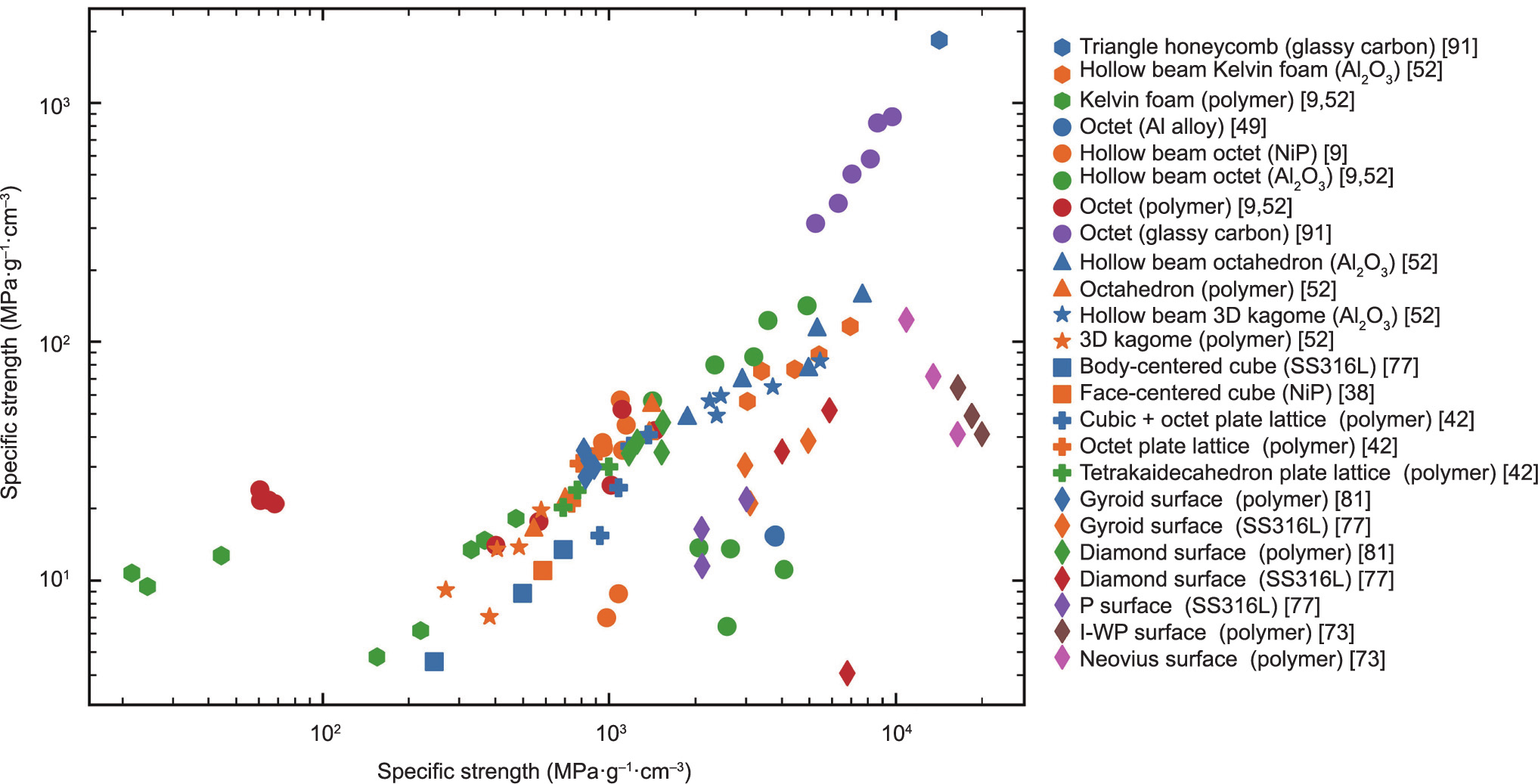
Fig. 4. Specific yield strength versus specific stiffness property chart of the discussed beam-based, plate-based, and minimal surface-based topologies.
Plate-based topologies, as closed-cell networks, can transfer loads efficiently between neighboring members [32]. Due to the interconnectivity of the material, plate-based topologies are potentially capable of achieving the H–S upper bounds [8]. Moreover, beam-based structures are sensitive to processing-related imperfections [92,95,96], so such structures with large-span horizontal struts and uneven transitions show low manufacturability in AM processes [97,98]. Stress concentration and imperfections are likely to occur with sharp transitions and around the connections in these structures. Minimal surface-based topologies with a continuous smooth surface are expected to be useful as a potential geometry to address these problems. Because of their smooth shell and regular topology, these structures can transfer stress efficiently and avoid stress concentration under a load. In addition, minimal surface-based topologies can provide a suitable environment for cell attachment and growth due to their surface features [99]. Such topologies exhibit not only superior energy absorption characteristics, a light weight, defect insensitivity, and excellent thermal and acoustic insulation properties, but also higher AM manufacturability, due to their self-supporting characteristics [97,98] and capability for more biomorphic designs, compared with beam-based structures [99].
《2.2. Auxetic topologies》
2.2. Auxetic topologies
Auxetic materials (i.e., materials with an NPR) are another interesting class of materials; they exhibit lateral contraction instead of expansion when compressed and exhibit lateral expansion instead of contraction when stretched. The term ‘‘auxetic” is derived from the Greek word auxetikos, meaning ‘‘what tends to increase” [100]. From the theory of elasticity, the Poisson’s ratio for isotropic materials ranges from –1 to 0.5. However, the Poisson’s ratios of most monolithic bulk materials [101,102]↑ such as metals and polymers are positive. Hence, architected cellular materials are often required to achieve an NPR. Such an architected auxetic material was first proposed by Lakes in 1987 [6]. The NPR of auxetic materials stems from their deformation behavior, which strongly depends on the underlying topology. According to their topology and deformation behavior, a variety of auxetic metamaterials can be divided into four basic types: re-entrant structures, chiral structures, rotating rigid structures, and perforated sheet structures [23,25,103]. In the subsequent subsections, these different auxetic topologies and their associated deformation mechanisms are discussed.
↑ Unlike Young’s modulus and strength, Poisson’s ratio is generally length-scale independent [101,102] and is often calculated to determine the overall range of applied strains.
2.2.1. Re-entrant structures
The idea of a re-entrant structure can be easily understood by visualizing it as a variation of the traditional 2D honeycomb (Fig. 5(a)), for example by introducing concave cell walls to form bow-tie-like patterns (Fig. 5(b)) [104–106]. Its auxetic property originates from the hinging of the cell wall, which forms individual unit cells. This is evident when comparing a typical honeycomb with a re-entrant honeycomb in Figs. 5(a) and (b): The stretching of the traditional hexagonal honeycomb in the y direction results in the contraction of the lattice in the x direction (positive Poisson’s ratio), whereas the re-entrant bow-tie honeycomb expands in the x direction through rib-hinging under the same stretching. The idea is that when the outer angled ribs are moved outward they can reenter as horizontal ribs and stretch in the horizontal direction. Such an idea was first used by Lakes [6], who transformed traditional open-cell foams into re-entrant foams by permanently compressing the ribs into inward protrusions. The degree of inward protrusion (i.e., the change of the unit cell shape) controls the macroscopic Poisson’s ratio. Later, it was shown that the Poisson’s ratio of re-entrant structures can vary from negative to positive with the geometrical change of the unit cell [107,108].
Aside from re-entrant structures with bow-tie-like cell walls, more topologies based on the re-entrant mechanism have been found; for example, an auxetic arrowhead structure (shown in Fig. 5(c)) was developed using topological optimization technology [109]. The Poisson’s ratio of the arrowhead structure was initially designed to be –0.8, but the value measured in the practical test was –0.92 [109]. Star-shaped re-entrant structures with a rotational symmetry order of n = 3, 4, and 6 (e.g., Fig. 5(d) has n = 4) can be constructed from the arrangement of arrowhead structures [110].
Another re-entrant honeycomb is the missing-rib structure (shown in Fig. 5(e)), which was proposed to explain the straindependent function of Poisson’s ratio [111,112]. This model has a better agreement with experimental results, such as the Poisson’s ratio and stress-train behavior, compared with other existing models. Most 3D re-entrant structures can be easily extended from 2D re-entrant structures (e.g., Figs. 5(b) and (f)) [113]. In addition, elastic instabilities (buckling) can be exploited to extend the concept of re-entrant structures [114], such as the buckling-induced auxetics ‘‘Bucklicrystals” (Fig. 5(g)) [115]. Ren et al. [116] found that the auxetic behavior in the buckling-induced metamaterial was closely related to the base material, and the buckling-induced auxetic behavior disappears in a metallic material. However, the loss of auxetic behavior in a metallic metamaterial can be recovered by using a pattern scale-factor method [117].
《Fig. 5》

Fig. 5. Deformation of (a) a typical honeycomb network and (b) a re-entrant (bowtie) honeycomb network exhibiting an NPR. Reproduced from Ref. [104] with permission. (c) An arrowhead auxetic structure. Reproduced from Ref. [109] with permission. (d) A star form auxetic structure. Reproduced from Ref. [110] with permission. (e) A missing-rib auxetic structure. Reproduced from Ref. [111] with permission. (f) A bow-tie 3D re-entrant auxetic structure. Reproduced from Ref. [113] with permission. (g) Schematic of a six-hole Bucklicrystal and views of uniaxial compression on a Bucklicrystal. Reproduced from Ref. [115] with permission.
2.2.2. Chiral structures
Chiral honeycombs are composed of an array of cylinders (also referred to as ‘‘nodes”) connected by ligaments that are tangential to the cylinders. The cylinders rotate under a uniaxial load, followed by flexure of the ligaments, so chiral honeycombs exhibit an NPR. Unlike other auxetic structures that exhibit nonlinear behavior during deformation, the Poisson’s ratio of a chiral structure remains constant over a wide range of strains due to the ability of the ligaments to ‘‘wind” onto the nodes while maintaining the angles between the structural elements [118].
The concept of chiral auxetics originated from a chiral molecular structure consisting of ‘‘rigid hexamers” [119], and the structure was later realized as a 2D periodic structure known as a ‘‘hexachiral” structure (Fig. 6(a)) [25,120]. The ‘‘hexa” in hexachiral comes from the fact that each unit cell consists of a central cylinder (node) tangentially connected to six ligaments; for example, a trichiral structure consists of unit cells with three ligaments per node. Depending on the tessellation of such unit cells, chiral structures can be further classified into chirals, in which the nodes are on the opposite sides of a ligament, as in the tetrachirals and trichirals in Fig. 6(b); anti-chirals, in which the nodes on the same side of a ligament, such as the anti-trichirals and anti-tetrachirals in Fig. 6(c); and meta-chirals, in which there is a mix of chirals and anti-chirals, such as the meta-hexachirals and metatetrachirals in Fig. 6(d) [121].
《Fig. 6》

Fig. 6. (a) The hexagonal chiral honeycomb proposed by Lakes and its deformation under compression. Reproduced from Refs. [25,120] with permission. Classification of basic units: (b) chirals; (c) anti-chirals; and (d) meta-chirals. Reproduced from Ref. [121] with permission.
In terms of performance, the Poisson’s ratio of a chiral structure generally depends on the ligament/cylinder wall thickness-tocylinder radius ratio, t/r, and on the ligament length-to-cylinder radius ratio,  . It was found that hexachirals [118,122], tetrachirals [118,122], and anti-tetrachirals [122] exhibit a Poisson’s ratio of –1 at low t/r, and their NPRs are insensitive to
  when compressed in the x or y direction (parallel to the lines connecting adjacent cylinders) [122]. On the other hand, it was shown that trichirals exhibit a positive Poisson’s ratio over a full range of t/r and , and that the Poisson’s ratio of anti-trichirals switches from negative to positive as is increased [122]. More detailed analytical analyses on common chirals and anti-chirals can be found in Ref. [123]. Meta-tetrachirals (in which there are rectangular nodes instead of cylinders) were shown to exhibit both auxetic and traditional honeycomb behavior (i.e., a positive Poisson’s ratio), depending on the geometric parameters [121]. In addition, due to their high anisotropy (involving a mix of tetrachirals and antitetrachirals, hence relaxing the constraints on rotational symmetry), meta-tetrachirals can achieve an NPR of much less than –1 [121].
2.2.3. Rotating structures
A rotating structure consists of rigid geometries (often squares or rectangles) connected through simple hinges. When loaded, the structure will expand under uniaxial tension (Fig. 7(a)) [124] and contract under uniaxial compression (auxetic behavior). The idea of using a rotating mechanism to achieve an NPR was first proposed by Grima and Evans [124,125], who modeled rotating structures using the principle of conservation of energy and showed that both rotating-square and rotating-triangle structures are isotropic and exhibit an NPR = –1. Later, the work was extended to more general rotating-rectangle structures with two different connectivities based on the shape of the empty space between four connecting rectangles (length  × width b): type I (rhombi of size × and b × b in Fig. 7(b)) and type II (parallelograms of size × b in Fig. 7(c)) [126,127]. Type I structures have the same connectivity as rotating-square structures [124] but have been shown to be anisotropic and to have a Poisson’s ratio varying from negative (even less than –1) to positive, depending on the /b ratio and the angle between the adjacent connecting rectangles [126]. Type II structures have been shown to mimic the exact mechanism of the rotating-square structure (isotropic and exhibiting an NPR = –1) [124], albeit with completely different connectivity [127]. Other structures consisting of rotating rhombi [128], rotating parallelograms [129,130], and a mixture of different-sized rotating squares and rectangles [131] have also been studied and have been generally shown to have a wide range of Poisson’s ratios, depending on the loading direction, rotating geometry, and extent of open space between them.
《Fig. 7》
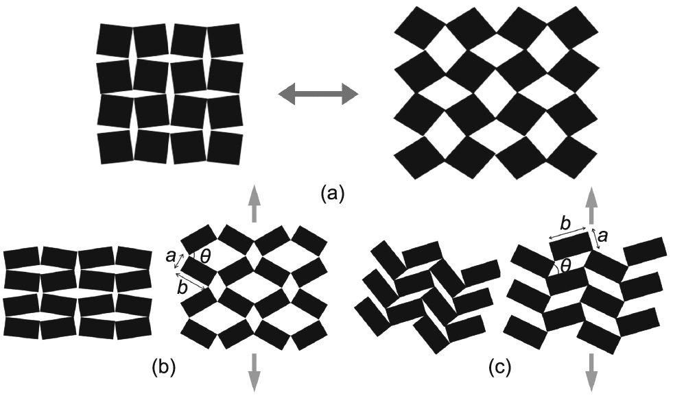
Fig. 7. (a) Illustration of a rotating-square structure and its deformation behavior. Reproduced from Ref. [124] with permission. (b) A type I rotating-rectangle structure exhibiting rhombus-shaped empty spaces: (left) original state; (right) after tensile loading. Reproduced from Ref. [127] with permission. (c) A type II rotating-rectangle structure exhibiting parallelogram-shaped empty spaces: (left) original state; (right) after tensile loading. Reproduced from Ref. [127] with permission.
More recently, hierarchical auxetics [132] have been developed by arranging smaller rotating squares sequentially within larger rotating squares ranging in three orders of hierarchy, from level zero to level three. This allows a wide range of NPR (in comparison with non-hierarchical rotating squares, which have an NPR = –1), which is significantly direction dependent, as the in-plane Poisson’s ratios obtained from different principal axes (υ12 and υ21) are considerably different. Furthermore, the pores between squares at different levels of hierarchy open up to a different extent, providing unique tunability for a wide variety of applications [132]. In addition, buckling-induced auxetic metamaterials can be designed directly using the rotating mechanism [133].
2.2.4. Perforated sheet structures
Perforated sheets with specific perforation patterns can be manufactured from readily available conventional block or sheet materials, providing an easy method for manufacturing auxetic systems at any scale [134]. Bertoldi et al. [114] introduced a square array of circular holes into cellular solids to achieve auxetic behavior. However, Bertoldi’s systems only exhibited NPRs when in the pre-compressed condition. Grima and Gatt [134] complemented this idea of using perforation patterns and uncovered a mechanism that resulted in NPRs. They demonstrated that perforated sheets of conventional material containing diamond-shaped or star-shaped perforations can show auxetic behaviors in both compression and tension, and that these perforated sheets can be seen as mimicking the behavior of rigid rotating structures. Some typical examples of perforated sheets are shown in Figs. 8(a–d) [134]. Grima et al. [135] used both finite elements and an analytical method to explain the auxetic behavior found in sheets with star- or triangular-shaped perforations, and provided an easy method to fabricate these shaped perforated sheets.
《Fig. 8》
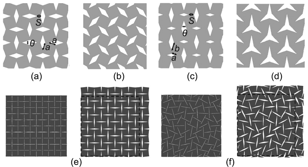
Fig. 8. (a–d) Typical examples of perforated sheets: (a, b) Systems A and B, which mimic the rotating-squares model, have diamond-shaped inclusions of the same size but different orientations; (c) system C, which mimics the rotating-rectangles model, has diamond-shaped inclusions of two different sizes; and (d) system D, which mimics the rotating-triangles model, has a star-shaped inclusion. Reproduced from Ref. [134] with permission. (e) A slit-perforated auxetic metamaterial with ordered slit orientation and its deformation behavior. (f) A slit-perforated auxetic metamaterial with disordered slit orientation and its deformation behavior. (e, f) Reproduced from Ref. [138] with permission.
The perforation patterns that have been proposed thus far to resemble this specific deformation mechanism have one common feature: Each large segment of material is surrounded by three or four cuts or perforations, which are placed in such a manner to resemble a ‘‘triangle” or ‘‘square” rotating unit. The material at the region connecting the rotating units together acts as a ‘‘joint,”which can be represented by the distance, s (Fig. 8(a)). These regions suffer from many stress concentrations when the rotating units rotate in these systems; therefore, aside from the shape and arrangement of the perforation patterns, the mechanical properties are also determined by the dimensions of this region [136].
Mizzi et al. [137] further developed the potential of perforation patterns by using patterned slit perforations, as shown in Fig. 8(e) [138]. These new auxetic systems can resemble a large variety of auxetic systems, such as rotating, re-entrant, and chiral structures. The so-called ‘‘giant negative” Poisson’s ratio of the proposed auxetic metamaterial can reach –13. In addition to being able to convert a previously nonauxetic sheet of material into an auxetic material, this novel method significantly reduces material waste [137]. In order to uncover the mechanism governing the manufacture of auxetic metamaterials through the use of slit perforations, Mizzi et al. [139] used finite-element analysis to explain the deformation behavior of ‘‘I”-shaped slit-perforated auxetic metamaterials, and compared these perforated systems with those predicted by previously formulated theoretical models. The researchers suggested that these systems have the potential to exhibit a wide range of NPRs, from giant negatives to zero. Although many perforation patterns—such as circular holes, star-shaped, diamondshaped, and slits—have been proposed, all of these works considered highly symmetric, ordered perforation patterns. Grima et al. [138] proposed a new class of perforated systems based on disordered and random slit orientations (Fig. 8(f)). They suggested that a high degree of symmetry is not necessarily required for a perforated system to exhibit auxetic behavior. More importantly, their work significantly reduced the complexity of the design and manufacturing of auxetic metamaterials.
Thus far, in most studies, auxetic perforated systems only exhibit auxetic behavior within the classic isotropic limit, which can be attributed to the fact that most of the auxetic mechanisms mimicked by these perforated systems cannot exhibit a large range of NPRs. Mizzi et al. [136] proposed a class of highly anisotropic auxetic perforated metamaterials that are highly tunable and have the potential to exhibit a large range of Poisson’s ratios. Recently, a machine learning (ML) model was introduced to accelerate a perforated metamaterial design. Wang et al. [140] used ML models to develop a novel planar auxetic metamaterial by introducing orthogonally aligned oval-shaped perforations. Their work suggested that the ML solution model can provide accurate predicting results rapidly without the limitations of explicit solution expressions.
2.2.5. Other types of auxetic structures
A new class of tensile network microstructures has been described, which can produce auxeticity with the existence of micro-rotational degrees of freedom [141]. The microstructure that exhibits an NPR consists of a network of nodules interconnected by fibrils. A microporous structure of expanded polytetrafluoroethylene (PTFE) based on the micro-rotational mechanism was found to have a giant NPR as large as –12 [141]. The expanded PTFE, which consists of an interconnected network of discshaped particles and fibrils, initially starts in a compact configuration; next, a first expansion caused by the fibrils translates the particles. These particles then begin to rotate, which finally results in the fully expanded configuration [142]. A simple geometric nodefibril model and its deformation behavior are shown in Figs. 9(a– c) [143]. Upon the translation of particles, a maximum Poisson’s ratio was obtained at a small strain.
《Fig. 9》

Fig. 9. (a–c) Structural changes in an anisotropic tensile network: (a) undeformed; (b) partially deformed; and (c) fully expanded. Reproduced from Ref. [143] with permission. (d–f) Micrographs of a typical crumpled aluminum foil: (d) photograph of a deformed sample after compression; (e) 3D image; and (f) 2D segmented image. Reproduced from Ref. [145] with permission. (g) Origami materials exhibiting an auxetic effect. Reproduced from Ref. [149] with permission. (h) The Miura-ori design and folding directly affect the NPR. Reproduced from Ref. [150] with permission.
Crumpled sheets, as exemplified by crumpled paper balls, can be regarded as a class of auxetic metamaterials. The auxetic behavior can be observed in the expansion or unpacking of a thin foil that has been confined in a small volume. Alderson et al. [144] proposed a method for fabricating thin auxetic flat sheets and curved foams by means of uniaxial compression. Through detailed optical microscopy and Poisson’s ratio measurements, the auxetic behavior was found to be a result of a crumpled microstructure throughout the thickness of the sample. Bouaziz et al. [145] studied the mechanical behavior of crumpled thin aluminum foils through compression tests, which indicated that crumpled materials can present a hybrid mechanical behavior, between the behavior of a foam and that of an entangled fibrous material (Figs. 9(d–f)). The sheet’s deformation behavior, which originated from the presence of ridges [146] and cones [147], is also found in origami, an ancient paper-folding art. Origami constructed from flat sheets through a process of folding along creases reveals seemingly infinite possibilities, and has thus provided a wide variety of foldable structures for designing metamaterials. The Miura-ori sheet, which was proposed in the 1970s and was initially designed for solar panels for space missions, has been extensively studied. The typical Miura-ori structure exhibits an auxetic effect in the plane [148]. As shown in Fig. 9(g), the structure expands in the direction perpendicular to the external load direction [149]. The absolute value of the NPR of Miura-ori can be very large when it is folded closed to flatten the configuration (Fig. 9(h)) [150].
When designing auxetic metamaterials, the stiffness and strength of the structures are low as a result of the high porosity and low density. This inevitably reduces the bearing capacity and the impact resistance, limiting the structural applications of auxetic materials [21,41]. Therefore, designing auxetic structures with both a high auxetic effect and high stiffness is usually desirable. To conclude this section, we plot the Poisson’s ratio of all the auxetic structures discussed in Section 2.2 versus their normalized Young’s modulus (i.e., the ratio of the Young’s modulus of the auxetic structures to that of their base materials) in Fig. 10 [17,19,115,122,136,139,151–163]. For auxetic metamaterials, the Poisson’s ratio and stiffness are coupled and are closely related to their geometric parameters. In many auxetic structures, increasing the auxeticity tends to reduce the stiffness [151,160,164]. Compared with chiral and rotating structures, re-entrant structures and perforated sheets have a better performance in terms of their Poisson’s ratio and corresponding stiffness, which appear in the lower right corner of Fig. 10. Furthermore, coupling enhancement of the stiffness and auxeticity can be achieved in re-entrant structures [25,151,165].
《Fig. 10》
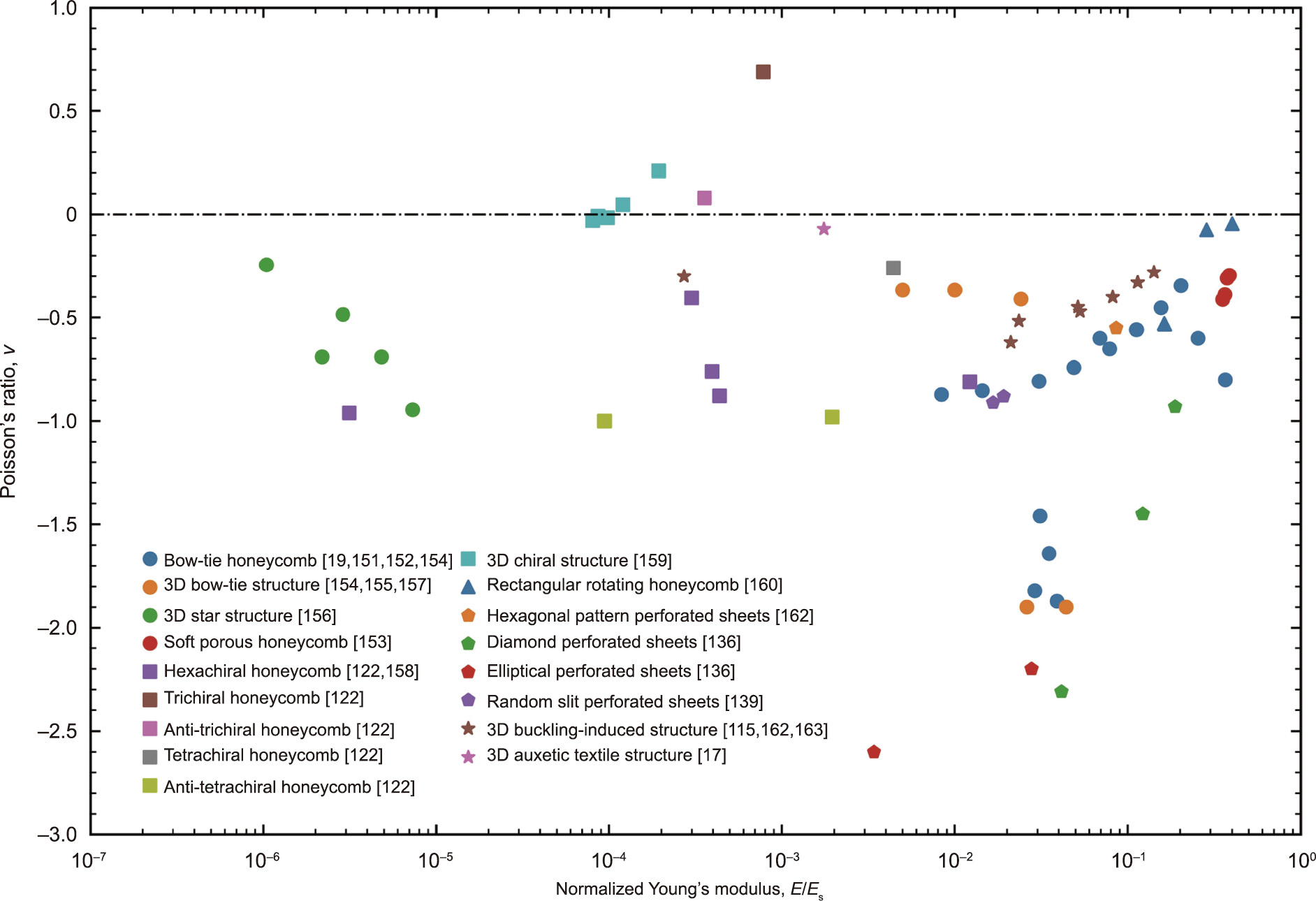
Fig. 10. A comparison of the Poisson’s ratios of auxetic structures: re-entrant structures (circular marks) [19,151–157], chiral structures (square marks) [122,158,159], rotating structures (triangular marks) [160], perforated sheets (pentagon marks) [136,139,161], and other types of auxetic structures (star marks) [17,115,162,163] versus the normalized Young’s modulus, which is the ratio of the Young’s modulus of the auxetic structures to that of their base materials.
《3. Additive manufacturing》
3. Additive manufacturing
《3.1. Self-propagating photopolymer waveguides》
3.1. Self-propagating photopolymer waveguides
The self-propagating photopolymer waveguide (SPPW) process is a technique to fabricate ordered, open-cell, interconnected, 3D polymeric lattice structures with microscale features [166,167] by shining an ultraviolet (UV) light through a 2D mask with circular apertures onto a container of photomonomer (Fig. 11(a)) [95,166,168–175]. The self-propagating waveguides come from the self-trapping effect of incident light in the polymer, which is caused by the change in the refractive index between the liquid monomers and the solid polymer. Due to this phenomenon, SPPW can fabricate high-aspect-ratio beams with a constant crosssection, making it ideal for the fabrication of 3D beam-based topologies. While the topologies can be controlled by the aperture pattern on the mask and the orientation of the incident UV light, the unit cell size and the smallest feature size of the resulting topologies depend on the aperture diameter and the spacing on the mask, and the overall material thickness is governed by the maximum propagation length of the waveguide. To achieve greater material thickness, a multilayer strategy can be utilized [22].
As mentioned above, SPPW-manufactured lattices consist of solid polymeric beams. However, by means of electroless plating or nanoscale depositions, a thin metal film is coated on the solid polymeric beams; after removal of the polymer, metamaterials comprised of interconnected hollow tubes can also be obtained. For example, nickel (Ni) hollow-tube micro-lattices (shown in Fig. 11(b)) were fabricated by means of SPPW followed by electroless nickel–phosphorous plating and polymer etching [38]. From the compressive stress–strain curves (Fig. 11(c)) and deformation maps (Figs. 11(d–f)), it is evident these micro-lattices can recover after 50% compression. Other studies have also showed that these hollow-tube micro-lattices exhibit high strength, energy absorption, and recoverability [95,168,169,171]. It is notable that all of the abovementioned micro-lattices were manufactured using positive templates and masks with relatively small apertures. SPPW can also be used with negative templates and masks with large apertures to fabricate Schwarz P-like shells called ‘‘Shellular,” which have been shown to have a higher Young’s modulus and strength than hollow-tube micro-lattices [78,176].
《Fig. 11》

Fig. 11. (a) Schematic of the SPPW process used to fabricate a micro-lattice structure. Reproduced from Ref. [175] with permission. (b) Images of two SPPW and postprocessed (via electroplating and removal of the polymer) Ni hollow-tube micro-lattices and magnified views of the hollow tubes. (c) Stress–strain curves of the microlattices exhibiting recoverable deformation (corresponding to (d–f)). Recoverable deformation of Ni micro-lattices: (d) before deformation; (e) under 50% compression; and (f) full recovery after removal of the load. (b–f) Reproduced from Ref. [38] with permission.
In comparison with other AM technologies, SPPW is limited in regard to the manufacturing of arbitrary topologies such as platebased or minimal-surface-based topologies, as it can only fabricate variants of beam-based topologies [175]. In addition, the prolonged exposure to UV light that is required to reach the maximum length of the waveguide often results in beams with diameters that deviate slightly from the initial design (i.e., are slightly thicker) [166]. The main advantages of SPPW are its higher fabrication speed, as entire polymeric micro-lattices can be formed in minutes, and its higher planar scalability, as fabrication rates of more than 1 m2 per minute are achievable [22,175]. These characteristics make SPPW an attractive option for the large-scale mass manufacturing of 3D micro-architected lattice materials.
《3.2. Projection micro-stereolithography》
3.2. Projection micro-stereolithography
Micro-stereolithography (μSL) uses UV light or a laser to selectively cure a photo-initiated resin and then construct 3D materials at microscale resolution in a layer-by-layer fashion [177–182]. In general, there are two types of μSL processes: vector scanning, such as two-photon lithography, in which each sectioned layer is scanned by a focused laser beam line by line and the entire layer is not exposed to the laser at the same time [183–185]; and mask projection, in which each sectioned layer is entirely exposed to a UV light at the same time through a dynamic mask that changes its pattern after each exposure [185–188]. Compared with scanning μSL, projection micro-stereolithography (PμSL) has a lower—albeit still adequate—resolution and the outstanding advantages of high fabrication speed and low production cost [189,190].
The basic schematic for a PlSL process (shown in Fig. 12(a)) is as follows: ① 3D computer-aided design (CAD) models are sliced into bitmap images. ② Next, each bitmap image is sequentially fed into a dynamic digital mask (i.e., a liquid crystal display [191] or digital micromirror device [182,192]), one slice after another. ③ Each image slice pattern is then projected through a reduction lens onto the surface of the photocurable resin via the vertical adjustment of an elevator that exposes a new layer after the previous layer is exposed. Although the resin in a PμSL process must be a photopolymer, a wide range of resin properties such as different stiffnesses [193], viscosities [194], and electrical conductivities [195] can still be achieved. Furthermore, other constituent materials such as metals and ceramics can also be obtained by postprocessing the as-formed polymeric structures—for example, by the electroless plating of a metallic coating or by the atomiclayer deposition of a ceramics coating. Examples of PμSL-manufactured polymeric, metallic, and ceramic octets are shown in Figs. 12(b–e), along with enlarged views of their connecting beams in Figs. 12(f–i) [9]. Their Young’s moduli and strengths (shown in Figs. 12(j) and (k)) exhibit stretching-dominated behavior, as previously discussed for the octet topology in Section 2.1.1.
《Fig. 12》
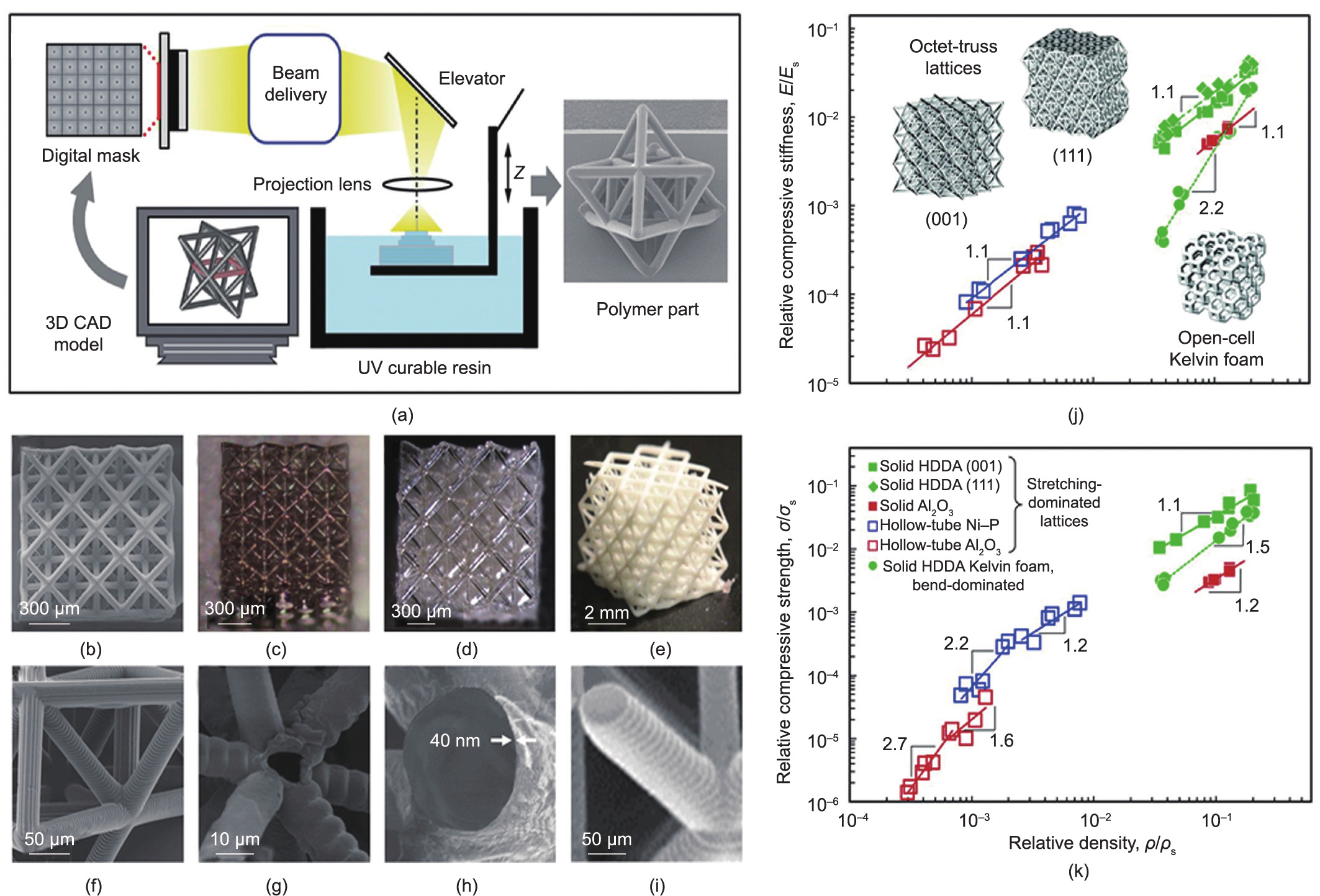
Fig. 12. (a) Schematic of the PlSL process to fabricate microscale 3D lattices. (b–e) Scanning electron microscope (SEM) images of octet-truss micro-lattices constructed from different strut configurations and constituent materials: (b) solid-tube polymer (1,6-hexanediol diacrylate); (c) hollow-tube metallic Ni–P film; (d) hollow-tube alumina; and (e) solid-tube alumina. (f–i) Magnified views of the lattice struts from (b) to (e), respectively. (j, k) Relative compressive stiffness and compressive strength versus relative density of fabricated stretching- and bending-dominated lattices. Reproduced from Ref. [9] with permission.
The main advantage of PμSL is its ability to fabricate 3D microscale structures with arbitrarily complex topologies (e.g., closedcell plate-based topologies) layer by layer while maintaining a relatively high fabrication speed [196–199]. Due to this advantage, PμSL has been used in many fields such as tissue engineering, biomedicine, metamaterials, micro-optical devices, and microelectromechanical systems (MEMS) [200–202]. In addition, largearea PμSL, which combines both a scanning mechanism and image projection via a deformable mirror device and scanning optics, has been developed to enhance scalability, with an overall size-toresolution ratio of 16 000 to 1 [203]. PμSL also has some inherent limitations: ① High-power UV light cannot be used, as it can damage the mask; ② smooth 3D structures are difficult to produce, as the layer-by-layer method always results in staircase-like surfaces; and ③ submicron features cannot be achieved. Until recently, the PμSL process was limited to using a single material; however, multi-material PμSL printing of 3D structures has now been achieved [204–206].
《3.3. Direct laser writing》
3.3. Direct laser writing
Direct laser writing (DLW) is a well-established technique for the fabrication of structures with nanoscale feature sizes down to 100 nm [207,208]. In this method, a laser beam is focused through an objective lens to cure photopolymers via single-photon or multi-photon absorption, as shown in Figs. 13(a) and (b) [209– 211]. Single-photon-absorption DLW is limited to the fabrication of 2D structures, since the single-photon absorption occurs within the entire area of the photopolymer that is exposed to light (Fig. 13(b)) [209]. On the other hand, multi-photon absorption— which often comprises two-photon absorption, also known as two-photon polymerization—occurs at an extremely small voxel at the focal point of the laser beam (Fig. 13(b)), where the light intensity is significantly high [212,213]; hence, arbitrary 3D structures with extremely small features can be fabricated from the voxel [214–217]. As a result, DLW is an attractive fabrication tool for the concept realization of metamaterial prototypes, such as optics [218,219], supercapacitors [220], and mechanical metamaterials for space applications [221,222].
The basic components of a DLW process include video imaging, a pulsed UV laser, a microscope objective lens, a sample holder, and a scanning stage [214]. The working mechanism is to control the highprecision laser beam to scan onto the photoresist. In conventional 3D-DLW, the achievable height of the sample is limited due to the limitation of the objective lens and the refractive index mismatch. A modified technology called dip-in DLW was devised to overcome this limitation [223]. In dip-in DLW, instead of immersion fluid, a liquid photoresist is used, the substrate of which does not need to be transparent. Fig. 13(c) shows two examples of four-fold and sixfold re-entrant structures with submicron features fabricated by means of dip-in DLW [223]. DLW-manufactured structures can also be post-processed; for example, alumina hollow-tube octet nanolattices (Fig. 13(d)) have been post-processed through atomiclayer deposition and oxygen plasma etching [92], and a glassy carbon nanohoneycomb (Figs. 13(e–h)) was post-processed through pyrolysis [91]. Most recently, DLW has successfully been used with a four-dimensional four-dimensional (4D) microprinting concept to construct reconfigurable compound micromachines [224].
《Fig. 13》

Fig. 13. (a) Schematic of the optical setup of DLW: (b) single-photon polymerization (left) and two-photon polymerization (right). Reproduced from Ref. [211] with permission. (c) Electron microscopy images of re-entrant structures fabricated using the dip-in DLW approach. Reproduced from Ref. [223] with permission. (d) Compression experiments on thin-walled alumina nano-lattices fabricated using DLW. Reproduced from Ref. [92] with permission. (e) A polymeric nano-lattice before pyrolysis; (f) the corresponding magnified view of the unit cell. (g) A pyrolyzed nano-lattice that isotropically shrinks to 20% of its initial size while the polymeric nano-lattice (shown in (e)) is transformed to a glassy carbon nano-lattice; (h) its magnified view. (e–h) Reproduced from Ref. [91] with permission.
Compared with other AM techniques, DLW has the highest achievable resolution. In particular, DLW is suitable for microand nano-metamaterials in a variety of fields, such as flexible micro-scaffolds [225] and nanophotonic structures [208]. DLW can construct materials without the need for supporting materials or a layer-by-layer process because it can induce polymerization precisely within any spatial position of a thick-film photoresist[226]. Despite these benefits, DLW is not widely used for the mass manufacturing of products in all industries because it is much less scalable than other techniques. In addition, the apparatuses required for DLW, which include femtosecond lasers, control systems, and optics, are very expensive. The choice of photoresist materials is also limited due to the high transparency requirement for the penetration of laser beams; it is difficult to fabricate materials containing ceramic or metal particles, which can impede laser penetration [226].
《3.4. Self-assembly》
3.4. Self-assembly
The self-assembly approach, which occurs through polymer, colloidal, or emulsion phase separation, is a promising method for nanofabrication that can transform disordered components into patterns and structures spontaneously [227]. Interactions between these components are usually non-covalent; they include hydrogen bonding, electrostatic attraction, hydrophobic and hydrophilic interactions, and van der Waals interactions [228], which can work together to transform a self-assembly system under thermodynamic non-equilibrium conditions into well-organized nanostructures in a stable state [3]. By exploiting autonomous microphase separation to produce well-organized nanostructures, selfassembly solves limitations such as a low throughput volume, poor scalability, and prohibitive cost that are encountered in the other nanomanufacturing technologies [229]. Thus, self-assembly is a competitive alternative technique to construct materials with tunable morphology and functionality [230].
Block copolymer (BCP) self-assembly, a polymer phaseseparation process, is a powerful means for the large-scale manufacturing of nanomaterials [229]. Due to advances in polymer synthesis methods, such as anionic or living radical polymerization [231,232], BCPs can be prepared with precisely controlled molecular weights and chemical properties [230,233,234]. Such BCPs usually consist of two or more chemically distinct components covalently bonded together. The driving force behind the selfassembly process originates from the thermodynamic incompatibility that causes the microphase separation of BCPs into a variety of ordered nanoscale morphologies, such as spheres (S), cylinders (C), gyroids (G), and lamellae (L) [235–237], as shown in Fig. 14(a), while macroscopic phase separation is prevented by the covalent bonds between the blocks [238,239]. Double-gyroid topology (i.e., a gyroid topology with two opposite chiralities; Fig. 14(b)) has also been successfully constructed through poly (isoprene)-block-poly(styrene)-block-poly(ethylene oxide) (PI-bPS-b-PEO), a triblock copolymer [240], and poly(4-fluorostyrene-r-styrene)-block-poly(D,L-lactide) (PS-b-PDLLA), a diblock copolymer [241]. The resulting 3D polymeric topologies can be postprocessed further for material conversion; for example, postprocessing involving nickel electrodeposition followed by polymer dissolution will result in Ni double-gyroid films, as shown in Figs. 14(c) and (d) [241].
《Fig. 14》
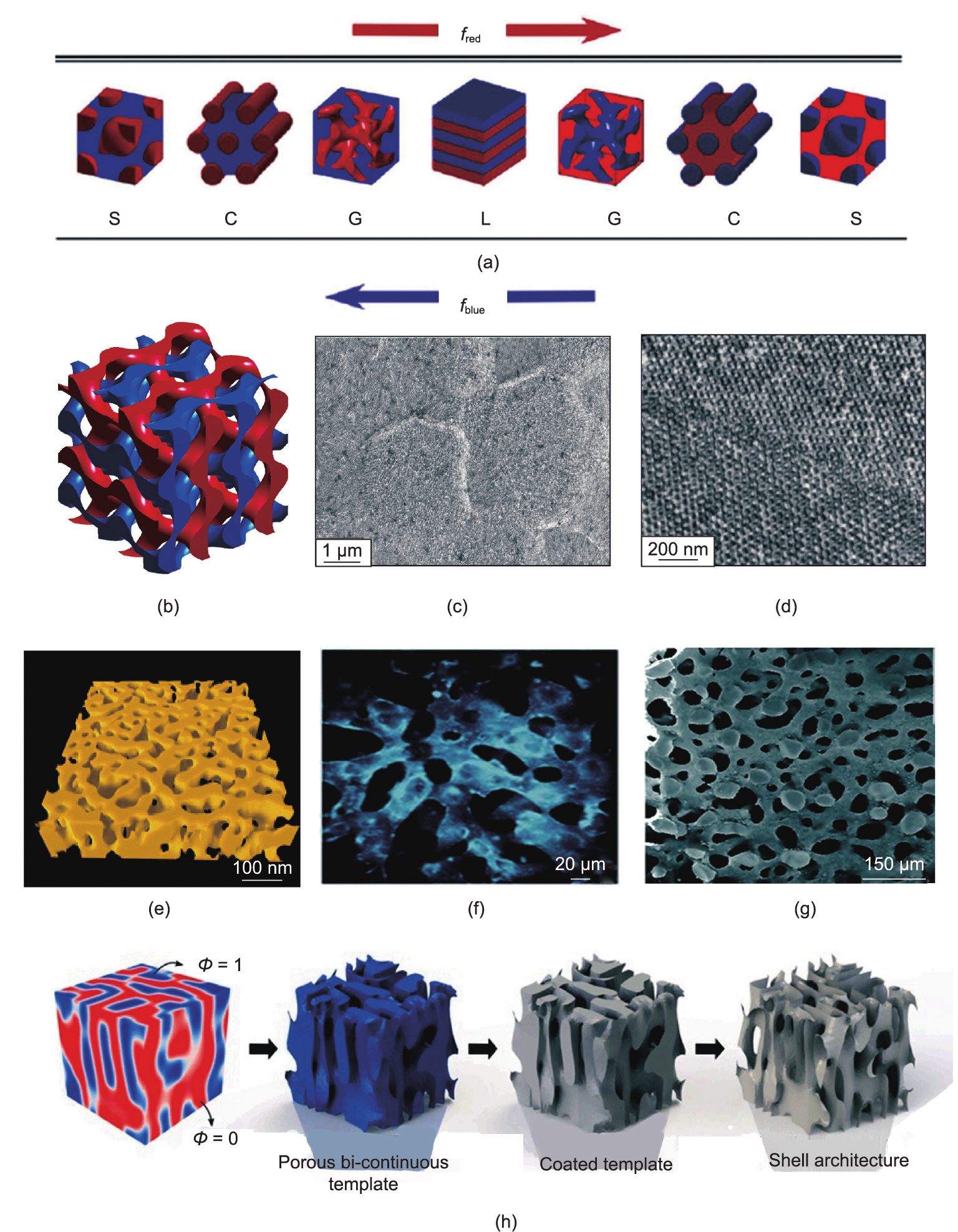
Fig. 14. (a) Diblock copolymer morphologies vary as the volume fraction changes between red and blue polymer blocks. Reproduced from Ref. [239] with permission. (b) A double-gyroid structure consisting of two single interpenetrating gyroid structures. (c) SEM image of Ni double films and (d) the corresponding magnified view. (b–d) Reproduced from Ref. [241] with permission. (e) 3D electron tomographic reconstruction of the nanoporous gold (spinodal topology) resulting from dealloying the Au–Ag alloy and then removing Ag. Reproduced from Ref. [247] with permission. Spinodal-decomposed bijels (f) before selective polymerization and (g) after selective polymerization. Reproduced from Ref. [88] with permission. (h) Schematic of polymeric microemulsion self-assembly followed by postprocessing steps to fabricate an alumina spinodal shell. Reproduced from Ref. [86] with permission.
Metal dealloying [242,243] or microemulsion self-assembly (often of polymers [244,245] or bicontinuous interfacial jamming emulsion gels known as ‘‘bijels” [88]) is another method that enables scalable micro- or nano-fabrications, with an overall sample size of up to a few centimeters. These self-assembly processes often undergo spinodal decomposition [85] (i.e., phase separation), resulting in stochastic spinodal topologies [10]. In metal dealloying self-assembly—such as electrochemically dealloying gold–silver (Au–Ag) [246,247] and gold–copper (Au–Cu) [248]—the less noble metal is dissolved away, while the more noble metal forms the nanoporous spinodal topology (Fig. 14(e)) [247,249]. However, this approach is only suitable for thin films of materials, where the thickness is usually about one order of magnitude less than the length and width.
In polymeric microemulsions, heat or UV light is used to initiate the polymerization-induced phase separation of a mixed solution composed of two monomers, porogenic solvents, and curing agents, such that the monomers separate from the solvent and crosslink to form a fully 3D polymeric sample whose length, width, and thickness are on the same order of magnitude, with spinodal topologies after extraction of the solvent. 3D porous spinodal samples, as shown before selective polymerization in Fig. 14(f) and after selective polymerization in Fig. 14(g), can also be selfassembled via bijel templating, in which the phase morphology is controlled by jamming nanoparticles at the interface between two partially miscible fluids undergoing spinodal decomposition; this is followed by the selective polymerization of one of the fluid phases and the draining of the other phase [88,250,251]. These polymeric samples can be further processed to obtain ceramic or metallic spinodal topologies; for example, alumina spinodal shells can be fabricated through the atomic-layer deposition of Al2O3 followed by polymer removal (Fig. 14(h)) [86].
In comparison with other AM techniques, self-assembly provides a unique opportunity for the low-cost, rapid, and highly scalable manufacturing of 3D structures with microscale or nanoscale features. However, the ability of self-assembly processes to fabricate diverse morphologies (e.g., octet or cubic plate lattices) is still very limited. It is also very difficult to control the self-assembled final topology [228]. In addition, defects resulting from largescale manufacturing often exist throughout the overall sample [22]. More efforts must be made to solve these problems.
《4. Conclusion and future directions》
4. Conclusion and future directions
From the past to the present, scientists have made significant progress in the topological designs of a wide variety of mechanical metamaterials, especially lightweight and auxetic materials. Due to rapid advancements in AM technologies, many of these topologies—which could only be studied theoretically or numerically in the past—can now be fabricated with the smallest feature size down to the microscale or nanoscale in an efficient and costeffective manner. By combining the optimal topology with the nanoscale size effect (i.e., nano-lattices), unprecedented specific strength can be achieved while simultaneously optimizing all the scale-independent properties, such as the Young’s modulus, specific surface area, coefficient of thermal expansion, and auxeticity. This concept of exploiting the synergy between multiple design parameters (e.g., size effect and topology) in nano-lattices serves as just one example of a new class of emerging mechanical metamaterials that go beyond topology alone. Hence, we give our opinion below on the challenges and future research directions of these emerging mechanical metamaterials in five different aspects: hierarchical design, unstable and nonlinear design, dynamic response, multiple materials and 4D printing, and ML.
《4.1. Hierarchical design》
4.1. Hierarchical design
Structural hierarchy entails the design of multiscale materials. These materials consist of higher-order structural elements at a larger scale, which are themselves composed of lower-order structural elements at a smaller scale. Such a hierarchy can go down several orders at smaller and smaller scales, which allows a much smaller overall relative density while maintaining the aspect ratio of the highest-order structural elements. For example, hollowbeam lattices can be obtained at much smaller relative densities than their counterpart solid-beam lattices with the same beam aspect ratio by decreasing the shell (i.e., lower-order elements) thickness of the hollow beams (i.e., higher-order elements). As a result, a significant increase in materials’ buckling resistance can be achieved at low relative densities [252]. Improved fracture toughness, energy absorption, and recoverability can also be obtained through complex hierarchical designs. Although complex hierarchical designs can now be manufactured by means of DLW [253] and large-area PμSL [203] with thin-film deposition, upscaling remains very limited. On the other hand, bijel self-assembly [250] provides a means for the scalable fabrication of hierarchical designs, although it is limited to spinodal topologies. More efforts are needed in developing hybrid techniques that can potentially combine self-assembly with optical lithography for the scalable fabrication of various hierarchical designs.
《4.2. Unstable and nonlinear design》
4.2. Unstable and nonlinear design
Most mechanical metamaterials are designed to achieve unusual values for common mechanical properties, such as stiffness, Poisson’s ratio, or compressibility. Recently, more advanced design principles, such as instabilities and nonlinear responses, have been introduced into mechanical metamaterials to achieve unprecedented functionalities. Mechanical metamaterials that incorporate nonlinearities and instabilities can exhibit exotic functionalities, such as shape transformations, multistability, and programmability [27]. Nonlinear response is ubiquitous in slender elements, which exhibit large deformations under a small load. Elastic instability and large deformation can achieve geometric nonlinearities, even if the material remains in the near-linear regime. For example, mechanical metamaterials composed of regular arrays of elastic beams can undergo buckling instabilities in a reversible nonlinear manner under controllable loading conditions. Moreover, many elastic structures are considered to be multistable due to a rapid and irreversible ‘‘snap-through” instability. The geometric reorganization and multistability triggered by the instability make metamaterials more adaptive in response to external stimuli. We believe that designing mechanical metamaterials by harnessing nonlinearities and instabilities will lead to more advanced functionalities, such as reconfigurable and programmable properties, which will allow metamaterials to enter a wider design space.
《4.3. Dynamic response》
4.3. Dynamic response
Many of the mechanical properties that have been reported for various architected materials are exclusively obtained under the quasi-static loading condition. In contrast, the mechanical properties of architected materials under dynamic loading conditions (e.g., ballistic impacts) are rarely studied [254]. Unlike quasistatic loadings, the length scale of traveling stress waves under dynamic loadings is much smaller than that of the unit cell size; in other words, the stress wave cannot traverse the whole material within the time in which the mechanical response of the material occurs [255], which results in large stress and strain gradients in the materials. Consequently, distinct deformations and failure mechanisms can be observed within the same architecture material. One possible design approach to counter such unexpected failures under dynamic loadings is to structurally grade the materials (e.g., change the unit cell size) such that the stress and strain fields become uniform. In addition to structural gradation, we believe that huge design opportunities exist regarding the dynamic properties of mechanical metamaterials that can be obtained by incorporating structural hierarchy, nanoscale material size effect, and so forth. Nevertheless, the dynamic property data of architected materials are very limited, and more studies are certainly needed.
《4.4. Multiple materials and 4D printing》
4.4. Multiple materials and 4D printing
In general, once mechanical metamaterials have been fabricated, the topology and function of the metamaterials are fixed and cannot be adapted to changes in the surroundings. With the advent of 4D printing, the limitation on fixed topology is lifted, and more advanced materials with shape-reconfigurable, selfdeployable, and mechanically tunable capabilities become possible [256]. Although 4D-printed structures can shape-morph over time in response to external stimuli, the morphing of single-material structures into complex curved shapes remains challenging to design and control. This problem has recently been overcome by the 4D printing of multi-material heterogeneous structures [257]. We believe that such a combination of 4D printing and multimaterial printing can significantly expand the material design space beyond the realization of materials’ shape-morphing ability; it opens a pathway for the fabrication of all-purpose universal composite materials with unprecedented time-varying multifunctional mechanical properties that were unattainable for traditional 3D-printed single-material structures.
《4.5. Machine learning》
4.5. Machine learning
Designing the next generation of materials goes beyond a quest for the enhancement of certain properties, as such materials also need to be adaptive, multipurpose, and tunable [258]. These goals cannot be achieved by traditional trial-and-error processes, either numerically or experimentally, which limits the search for untapped regions of the design space. Until now, mechanical metamaterials design has relied on extensive experiments combined with analytical or computational models that provide a posteriori explanation. However, ML, as a big-data-driven method [259– 261], can be used for accelerated multi-objective (e.g., base materials, length scales, and fabricating processes) material designs, even with few experiments. In recent years, ML has been used extensively and has demonstrated its practicality for designing and analyzing different mechanical metamaterials [258,262– 264]. While these works on ML-based material design have certainly laid a foundation for this fast-growing field, we are still at the very early stage, and we believe that ML will continue to play an important role in the discovery of new mechanical metamaterials.
《Acknowledgments》
Acknowledgments
This work was supported by the Guangdong Major Project of Basic and Applied Basic Research (2021B0301030001), project supported by the Space Utilization System of China Manned Space Engineering (KJZ-YY-WCL03), National Key Laboratory Foundation of Science and Technology on Materials under Shock and Impact (6142902210109), National Key Research and Development Program of China (2018YFB0905600 and 2017YFB0310400), National Natural Science Foundation of China (51472188 and 51521001), Natural Research Funds of Hubei Province (2016CFB583), Natural Research Funds of Shenzhen, Fundamental Research Funds for the Central Universities China, State Key Laboratory of Advanced Electromagnetic Engineering and Technology (Huazhong University of Science and Technology), the Science and Technology Project of the Global Energy Interconnection Research Institute Co., Ltd. (SGGR0000WLJS1801080), and the 111 Project (B13035).
《Compliance with ethics guidelines》
Compliance with ethics guidelines
Chenxi Lu, Meng-Ting Hsieh, Zhifeng Huang, Chi Zhang, Yaojun Lin, Qiang Shen, Fei Chen, and Lianmeng Zhang declare that they have no conflict of interest or financial conflicts to disclose.


 京公网安备 11010502051620号


