

《1. Introduction》
1. Introduction
The chemical industry is a major carbon emitter in China and must be focused on for China to achieve its goal of carbon neutralization. In the past ten years, carbon dioxide (CO2) emissions from the coal chemistry and petrochemical industries around the world have increased by more than 50 times (from 0.91 billion tonnes per year to 49 billion tonnes per year), and the contradiction between China’s aims of industrial development and environmental protection is becoming increasingly serious [1,2]. Recently, China stated its goal of achieving peak carbon emissions by 2030 and carbon neutralization by 2060. Carbon neutralization requires the carbon sink (i.e., the total amount of CO2 that is absorbed by plants and captured by humans) to able to completely offset carbon emissions. However, the current carbon sink in China is only about 1.5 billion tonnes per year, which is significantly less than the carbon emissions of the chemical industry [2]. Obviously, a huge gap needs to be crossed to achieve the goal of carbon neutralization.
Taking the coal chemical industry as an example, in modern coal chemical production, only 1/5–1/3 of the carbon in raw coal goes into products; the rest becomes a source of huge amounts of carbon emissions [2]. Furthermore, half of the energy consumption is directly discarded in various forms and eventually becomes ambient thermal pollution. Given these problems, in addition to significantly reducing the proportion of traditional fossil energy (e.g., coal, oil) in the energy structure, the efficient recycling utilization of CO2 and waste heat holds great importance [3]. Recently, high-temperature electrolysis technology based on solid oxide electrolysis cells (SOECs) has attracted increasing attention worldwide [1,4]. In combination with renewable energy, such as the rich wind power or photovoltaic energy in northwest China, SOECs operating at elevated temperatures can not only make full use of industrial waste heat but also convert CO2 into hydrocarbon fuel or high-value-added chemical products via electrochemical reactions, thereby simultaneously realizing the large-scale storage of renewable energy and the efficient utilization of CO2 (Fig. 1) [4–6]. More importantly, compared with other electrochemical techniques at lower temperature conversions (≤ 200 °C), such as transition metal electrodes in liquid electrolytes, SOECs operating at high temperatures of 800–1000 °C possess many unique advantages, including low impedance, low power consumption, high electrolysis efficiency, and less dependency on noble metal electrode catalysts [2]. Moreover, SOECs have the potential to operate stably even at relatively high current densities. As a comparison, the operating current density of alkaline electrolysis cells (AECs) is typically lower than 0.5 A∙cm–2 , while state-of-the-art SOECs can operate at a high current density of above 1.0 A∙cm–2 with low polarization loss and ignorable performance degeneration [4,7]. This implies that an SOEC stack can be designed to be much smaller than an AEC stack with the same electrolysis capacity. Therefore, SOECs can potentially be used to achieve modular flexible design for application in certain specific scenarios [2,7].
《Fig. 1》

Fig. 1. The high-efficiency conversion and utilization of CO2 in chemical processes based on high-temperature electrolysis. Reproduced from Ref. [4] with permission.
《2. The SOEC for CO2 conversion》
2. The SOEC for CO2 conversion
There are two main CO2 conversion approaches using SOECs at high temperature: pure CO2 electrolysis to CO and O2; and CO2 electrolysis in the presence of other substances (H2O, CH4, etc.), which is referred to as co-electrolysis and includes CO2/H2O and CO2/CH4 co-electrolysis [1]. This review article discusses both pure CO2 electrolysis and co-electrolysis in regard to CO2 hightemperature electrochemical conversion. The structure of a basic unit for CO2 conversion using SOEC is illustrated in Fig. 2 (in the case of pure CO2 electrolysis). This basic unit typically consists of a cathode, an electrolyte, and an anode. During the CO2 electrolysis (or co-electrolysis) process, CO2 (or CO2/H2O) molecules are reduced at the cathode/electrolyte interface to generate gaseous CO (or CO/H2) and O2–. These gases subsequently pass through the porous electrode with the assistance of a carrier gas; the generated O2– migrates through the dense electrolyte layer at elevated temperatures, and is subsequently discharged at the electrolyte/ anode interface to generate gaseous O2 [8–12]. The main reactions include the following:
《Fig. 2》
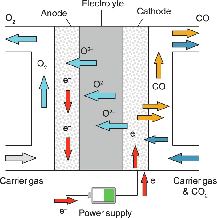
Fig. 2. Schematic diagram of the basic structure of an SOEC for CO2 conversion.
Cathode:

Anode:

Total reaction:

The co-electrolysis of CO2/H2O can not only realize the efficient conversion of electrical energy into chemical energy (H2 + CO, known as syngas) but also solve the problem of the recycling utilization of CO2; thus, this technology has attracted a considerable amount of attention [2,12]. CO2/H2O co-electrolysis is much more complicated than steam electrolysis due to the existence of the reverse water gas shift (RWGS) reaction, in which H2O is reduced into H2 in the forward electrolysis reaction, and CO2 is subsequently reduced by H2 [2,13]:

According to the existing literature, the Gibbs free energy change ( ) of the RWGS reaction is positive at relatively low temperatures but drops to 0 when the temperature is increased to approximately 800 °C [2]. This finding suggests that RWGS can be thermodynamically spontaneous under high-temperature coelectrolysis conditions (e.g., in the temperature range of 800– 1000 °C) and that increasing the temperature can further promote the conversion of CO2. The syngas produced by co-electrolysis can be further utilized in various chemical synthesis scenarios to produce a series of high-value-added products, such as methane, methanol, or ethylene [1,2,14].
Compared with co-electrolysis, pure CO2 electrolysis is less dependent on water resources—a characteristic that is of great importance in achieving carbon neutralization—although it possesses a higher technical threshold and presents more challenges at present stage [2,12]. With recent developments in the fundamental theory of electrochemistry and progress in related technologies, CO2 electrolysis is expected to become an emerging industrial technology [1,2]. In the National Aeronautics and Space Administration (NASA) Mars Exploration Program, SOECs were utilized to electrolyze the rich CO2 in the Martian atmosphere to fabricate oxygen propellant for space rovers [15].
Despite the broad application prospects of CO2 electrolysis or co-electrolysis, it should be noted that the molecular structure of CO2 is fundamentally more stable than that of H2O; thus, it is more difficult to cause CO2 electrolysis or co-electrolysis, in comparison with steam electrolysis. Therefore, novel SOEC component materials with relatively high electrochemical activity and operation stability should be developed to realize steady CO2 electrolysis or coelectrolysis [16]. The next sections introduce the latest research progress in SOEC cathodes, electrolytes, anodes, and other component materials that are applicable for CO2 electrolysis or coelectrolysis. Furthermore, the fundamental mechanism of the high-temperature electrochemical interfacial reactions in SOECs is discussed in detail to provide guidance for the rational design and optimization of high-performance cell components, as well as the design and integration of industrial-scale SOEC stacks and modules.
《3. Core components of an SOEC》
3. Core components of an SOEC
《3.1. Cathode materials》
3.1. Cathode materials
During the CO2 electrolysis process, CO2 molecules are discharged onto the SOEC cathode, a carbon reduction reaction occurs, and oxygen ions are generated (Eq. (1)). This reaction involves the fracture of two  bonds in the CO2 molecule and requires a relatively high activation energy. Hence, the fracture of the bonds is regarded as the rate-determining step in the whole CO2 electrolysis process. In order to reduce the activation energy and accelerate the reaction kinetics, the following characteristics are desirable for cathode materials: ① considerable electronic conductivity; ② considerable ionic conductivity; ③ the capability of chemical adsorption with CO2 molecules; and ④ coking resistance, in order to prevent coke from being generated and accumulating via the excessive reduction of CO2 during the electrolysis process.
3.1.1. Metal-containing cathodes
A series of metal–ceramic composite materials, such as the commonly used nickel–yttria-stabilized zirconia (Ni–YSZ), are currently the most extensively researched SOEC cathode materials. The classic fabrication method for a Ni–YSZ cathode involves cocombusting a mixture of nickel oxide (NiO), yttria-stabilized zirconia (YSZ), and pore formers (e.g., starch, poly(methyl methacrylate) (PMMA)) under oxidizing conditions, and then further reducing the mixture under a hydrogen (H2) atmosphere to obtain the target product [2]. In a Ni–YSZ composite electrode, metallic nickel (Ni) possesses good electronic conductivity and can provide active sites for CO2 chemical adsorption and electrochemical reduction. Sintered YSZ ceramic has good ionic conductivity and high mechanical strength, and thus plays a critical role in supporting the cathode. The pore former leads to the formation of a large number of pores in the electrode bulk phase after sintering, which can provide numerous channels for the diffusion and release of gaseous productions, such as H2 and CO.
Thus far, the electrochemical performance and durability of Ni– YSZ electrodes have been widely investigated in CO2 electrolysis and CO2/H2O co-electrolysis at the laboratory scale. In 2007, the Risø National Laboratory in Denmark reported that their Ni–YSZ| YSZ|LSM–YSZ (LSM stands for La1–xSrxMnO3–δ) stacks achieved stable CO2 electrolysis in a mixed atmosphere of 70% CO2 + 30% CO at 950 °C [9]. The operating current density reached 1.5 A∙cm–2 under a 1.29 V voltage, and the CO output reached 33 L∙h–1 . Another case in point was conducted by the Risø National Laboratory and Haldor Topsøe A/S, in which the researchers put 12 cm × 12 cm 10-cell SOEC stacks (Ni–YSZ|YSZ|LSM–YSZ) in a mixed atmosphere of 45% H2O + 45% CO2 + 10% H2 [17]. At 850 °C, stable electrolysis was achieved for 800 and 400 h under a current density of 0.50 and 0.75 A∙cm–2 , respectively, and no performance degradation was detected during operation. Despite these results, several studies have still indicated that Ni–YSZ cathodes may undergo a degradation process at high current densities or during long-term operation. For example, researchers from the Jülich Research Center investigated the long-term performance of Ni– YSZ|YSZ|LSCF (LSCF stands for lanthanum strontium cobalt ferrite) stacks in an H2O/CO2/H2 mixed atmosphere and found that the performance degradation rate was approximate 2%–4% per 1000 h when the current density was in the range of 0.300 to 0.875 A∙cm–2 ; moreover, the performance degradation rate increased to as high as about 6% per 1000 h when the electrolysis current density was elevated to above 0.875 A∙cm–2 [18].
The degradation mechanism of Ni–YSZ cathodes during CO2 electrolysis operation has also been extensively studied. Using impedance spectroscopy, Hauch et al. [19] investigated a Ni–YSZ| YSZ|LSM–YSZ stack and demonstrated that degradation of the electrolysis cell performance was significantly related to the increase in the polarization impedance of the Ni–YSZ cathode. In particular, they found that, under high temperature (e.g., 950 °C) and relatively high current density (e.g., 2 A∙cm–2 ), Ni migration and agglomeration were more likely to occur, significantly influencing the composition of the cathode/electrolyte interface, such as the formation of a dense Ni layer or a dense YSZ layer at the interfacial region, and significantly increasing the impedance of the cathodes. In another study, Skafte et al. [5] used in situ X-ray photoelectron spectroscopy (XPS) to investigate the degradation behavior of Ni– YSZ thin-film electrodes in a CO/CO2 atmosphere. They noticed obvious C—C sp2 and C—C sp3 signals on the electrode surface when the overpotential was increased to 150 mV at 750 °C, which were recognized to be from deposited coke, as demonstrated by scanning electron microscopy (SEM) (Fig. 3) [5]. Argyle and Bartholomew [20] proposed that the deposited coke may originate from the disproportionation reaction of CO on the surface of metallic Ni.
《Fig. 3》

Fig. 3. (a) SEM image of the Ni–YSZ surface after carbon deposition; (b) XPS peaks for three respective electrodes (Ni–YSZ, Ni–SDC, and SDC) at the overpotential when the cathodes started to deposit carbon in a CO/CO2 atmosphere (a.u.: absorbance unit). Reproduced from Ref. [5] with permission.
To improve the electrocatalytic activity and stability of the Ni– YSZ cathode during CO2 electrolysis at high temperature and high current density, researchers have developed various optimizing and modifying approaches, including surface modification by CeO2-based oxides [5,21–24]. For example, in the in situ XPS investigation carried out by Skafte et al. [5], it was found that, after replacing the YSZ component in the cathode with Sm0.2Ce0.8O1.9–δ (SDC) nanoparticles, carbon deposition did not occur until the extrinsic overpotential increased to about 300 mV, suggesting significantly enhanced surface coke resistance of the cathode in a CO/ CO2 atmosphere (Fig. 3(b)).
Extensive mechanism research has focused on possible reaction pathways for high-temperature CO2 reduction in SOEC systems. The results not only reveal the origin of carbon deposition but also provide guidance for the rational optimization of existing Ni–YSZbased cathode materials [5,20]. As illustrated in Fig. 4(a), it has been accepted that the CO2 reduction reaction on a Ni/YSZ surface involves the following fundamental steps: ① the absorption and activation of CO2 on the metallic Ni (surface + CO2 (g) → CO2* ); ② the breaking of the  double bond with the assistance of electron injection (CO2* + 2e– → CO* + μo); and ③ the desorption of CO (CO*
  CO (g)) [5]. The efficient utilization of CO2 requires catalysts that can activate the first double bond of CO2 while suppressing complete deoxidation and avoiding overreduction (CO* + 2e– → C* + μo) [5]. Unfortunately, theoretical simulation results suggest that coke generation on the Ni surface under the operating conditions is thermodynamically spontaneous. Under actual operation conditions, the coke-deposition phenomenon is widely observed, leading to the blocking of active sites on the cathode surface [5,17–19]. This is one of the most important degeneration issues of Ni–YSZ cathodes during the CO2 electrolysis process.
《Fig. 4》

Fig. 4. Possible CO2 reduction mechanism on the surface of (a) Ni–YSZ and (b) SDC under SOEC operating conditions; (c) cross-sectional SEM images of two types of cathode/electrolyte interfaces. Reproduced from Ref. [5] with permission.
As emerging candidates for SOEC cathode material, CeO2- related oxides can significantly enhance the long-term stability of the cathode [21–24]. This is because carbon atoms on the surface of a CeO2-based material (e.g., SDC, GdxCe1–xO2–δ (GDC)) can be trapped as oxidized carbon species rather than as solid carbon, which can mitigate and even kinetically prevent carbon deposition during CO2 electrolysis, as shown in Fig. 4(b) [5]. Papaefthimiou et al. [21] suggested that CeO2-based materials can participate in a carbon redox reaction via transformation between Ce(III) and Ce(IV), which substantially changes the CO2 reduction pathways. By using in situ XPS, Yu et al. [22] identified obvious carbonate signals at the surface during the reduction process when the Ni–YSZ cathode is modified with CeO2 or its derivatives. It is speculated that the carbon reduction reaction proceeds via the following mechanism:

This reaction mechanism for carbon formation on Ni–YSZ and SDC surfaces explains the fact that SDC-based systems possess significantly enhanced coking resistance under SOEC operating conditions. This can be further confirmed by the intact interface between the SDC electrodes and electrolytes in cross-sectional SEM images, as shown in Fig. 4(c). The results clearly suggest that ceria or ceriarelated oxides are promising and can be further developed as SOEC cathode candidates for catalyzing CO2 electrochemical reduction.
Neagu et al. [23] and Yue et al. [24] found that the carbon deposition reaction rate on the Ni surface also strongly depends on the size of the metallic Ni particles in the composite cathode. Christensen et al. [25] and Chen et al. [26] explained that, in smaller Ni crystal grains, the saturation concentration of carbon is relatively higher; thus, the electrode possesses a higher tolerance to carbon. According to this principle, developing a new electrode preparation process and reducing the average particle size of the metallic Ni should be an effective strategy to improve the carbon resistance of composite cathodes. For example, by means of a [Ni(acac)2] (acac stands for acetylacetone) precursor reduction, Han et al. [27] prepared Ni nanoparticles that were uniformly distributed on a silica surface, with an average particle size of only (5.2 ± 0.4) nm; after annealing these Ni nanoparticles at 800 °C under a methane (CH4) atmosphere for about 170 h, there was still no detectable coke deposition on the surface. Liang et al. [28] developed a urea combustion in situ synthesis process to prepare a NiO–YSZ electrode material precursor (where the NiO possessed a particle size of about 11 nm); after H2 reduction, fine and uniformly dispersed metallic Ni particles were generated on the YSZ matrix. However, the thermal and chemical stabilities of the metallic nanoparticles prepared by these methods still need to be further enhanced, and agglomeration of the metallic nanoparticles may become the main degeneration issue.
Another important series of materials that have been widely used as SOEC cathodes for CO2 electrolysis are copper (Cu)- containing composites [29–32]. In particular, Cu–CeO2–YSZ and its derivatives have been widely investigated as promising SOEC cathode materials, as these composites are inert for coke deposition and typically exhibit small decreases in the open circuit voltage (OCV) of the cell when exposed to a CO2 or CO atmosphere [32,33]. For experimental verification, Cheng et al. [34] fabricated an adherent layer of porous Cu/Gd0.1Ce0.9O2 (CGO) electrode on a YSZ electrolyte by sintering Cu/CGO paste onto a YSZ substrate. The Cu–CGO|YSZ|YSZ–LSM|LSM electrolysis cell based on this cathode was developed and exhibited no significant performance degradation during 2 h of CO2 reduction at 750 °C with a 1:1 CO2/CO feed. In another investigation, Su et al. [29] fabricated a Cu–SDC cathode supported on YSZ by means of an impregnating method and developed a Cu–SDC|YSZ|Cu–SDC symmetrical cell. The activation energy of CO2 electrolysis reduction via this cell was measured to be as low as about 1.57 eV under a CO–CO2 (50:50) or CO–CO2 (67:33) atmosphere; impregnating more Cu produced more Cu–CeOx interfaces and further lowered the activation energy. Liu et al. [33] developed a Cu/Ce0.6Mn0.3Fe0.1O2–δ electrode for a reversible solid oxide electrochemical cell with CO/CO2 as the shuttle. In the electrolysis mode, the current density reached up to 2.2 A∙cm–2 at 2.0 V and 800 °C. After 100 h of cycled operation between the SOEC and solid oxide fuel cell (SOFC) modes, the cell exhibited no degeneration, suggesting remarkable stability under CO/CO2 conditions. These results demonstrate that Cucontaining composites possess unique advantages when used as cathode materials for high-temperature CO2 electrolysis.
3.1.2. Perovskite-based cathodes
In recent years, it has been discovered that many perovskitebased oxides possess mixed ionic and electronic conductivity (MIEC) and considerable electrocatalytic activity, as well as high redox stability and resistance against coke deposition, suggesting that these materials can be used as superior SOEC cathode candidates [35–37]. Typical perovskite-based oxides include perovskite materials (ABO3–δ, where ‘‘A” is an alkaline earth or rare earth metal ion, and ‘‘B” is a transition metal ion), Ruddlesden–Popper materials (A2BO4+δ), and double-perovskite materials (AA' B2O5+δ), whose crystal structures are shown in Fig. 5 [2,38]. Many perovskite-based materials, including La1–xSrxCryMn1–yO3–δ (LSCM), La1–xSrxFeO3–δ (LSF), and La1–xSrxTiO3–δ (LST), exhibit remarkable stability under a wide range of oxygen partial pressures, and there are abundant oxygen vacancies on their surface, which provide active sites for CO2 chemical adsorption and subsequent carbon reduction [39–42].
《Fig. 5》
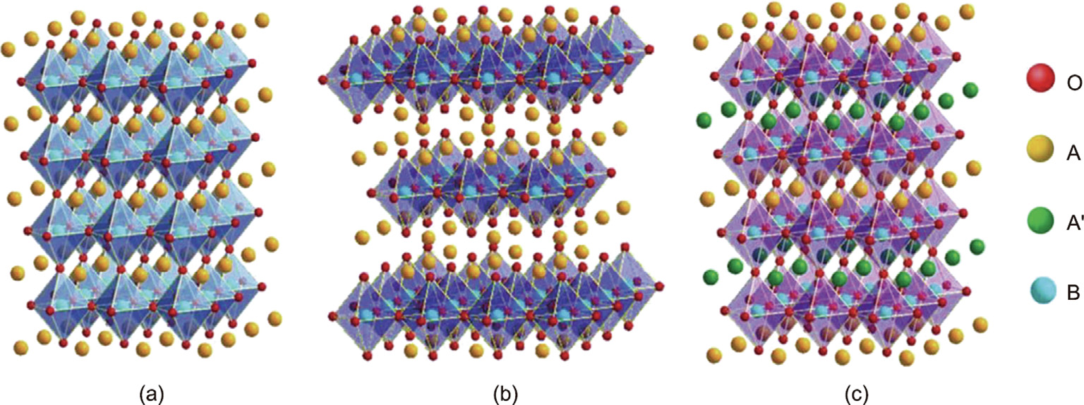
Fig. 5. Schematic diagram of the crystal structure of several perovskite-based oxides: (a) perovskite materials; (b) Ruddlesden–Popper materials; and (c) double-perovskite materials. Reproduced from Ref. [2] with permission.
LSCM, which has an acceptable ionic conductivity, remarkable electronic conductivity, and excellent durability under a CO/CO2- containing atmosphere, is one of the most widely used perovskite-based SOEC cathode materials for CO2 electrolysis or co-electrolysis [39,40,43]. Notably, YSZ or GDC are typically added into an LSCM cathode to enhance its ionic conductivity [40]. For example, using a vacuum infiltration method, Yue and Irvine [44] fabricated a Pd–GDC co-infiltrated LSCM cathode, which achieved a polarization resistance of only 0.24 Ω∙cm2 at 900 °C under a CO–CO2 (30:70) atmosphere. Zhang et al. [45] developed an LSCM–GDC/YSZ composite cathode by co-sintering LSCM and GDC nanoparticles onto a porous YSZ scaffold. At 800 °C and a current density of 0.29 A∙cm–1 , no particle aggregation or performance degeneration was observed during the 50 h test for the cathode. Recently, Ma et al. [46] synthesized an LSCM cathode using a glycine–nitrate process (GNP). An LSCM|YSZ|LSCF full cell based on this cathode showed a stable current density of 0.1 A∙cm–2 at 800 °C under an H2O–CO2 (60:40) atmosphere at 1.5 V for 24 h, demonstrating remarkable durability toward CO2 electrolysis and co-electrolysis.
LSF is another important cathode material candidate for high-temperature CO2 electrolysis [39,40,47]. In previous studies, Yang et al. [48] developed an LSF|LSGM|LSCF (LSGM stands for La0.9Sr0.1Ga0.95Mg0.05O3–δ) single cell and achieved a current density of 0.76 A∙cm–2 at 1.5 V and 800 °C under a pure CO2 atmosphere. Zhou et al. [49] fabricated a palladium (Pd) single site-anchored Pd–LSF–SDC cathode by means of ball milling and firing. The Pd–LSF–SDC|YSZ|LSM–YSZ single cell based on this cathode showed a highest average current density of 0.58 A∙cm–2 at 1.6 V and 800 °C under a CO2 atmosphere. These results demonstrate that LSF and its derivatives are promising candidates for cathode materials in high-temperature CO2 electrolysis.
In addition, many other perovskite-based materials exhibit good performance when applied as SOEC cathodes for CO2 electrolysis, including LST, (La,Sr)VO3 (LSV), and Sr2Fe1.5Mo0.5O6–δ (SFM), which have been introduced and comprehensively summarized in previous review articles [39,40].
3.1.3. Cathodes with exsolved nanoparticles
Recently, many studies have demonstrated that, under an appropriate reducing atmosphere, the B-site transition metal ions in perovskite-based materials can be reduced and then exsolved on the surface, generating metallic nanoparticles or simple oxides in what is known as B-site cation exsolution (Fig. 6(a)) [41,50]. Typically, these metallic nanoparticles not only possess excellent electronic conductivity and electrochemical activity but also show special stability under high temperatures and reducing atmospheres; therefore, they can significantly improve the electrochemical performance of perovskite-based cathode materials [23,51]. For example, Lv et al. [52] fabricated a doubleperovskite-structured Sr2Fe1.35Mo0.45Co0.2O6–δ electrode and treated it under a 5% H2/Ar atmosphere for 2 h at 800 °C to generate Co–Fe nanoparticles at the surface (Fig. 6(b)). They found that the polarization resistance of the electrode was reduced to about half of that before exsolution (Fig. 6(c)) [52]. Xie et al. [53] converted a NbTi0.5Ni0.5O4 cathode into Nb1.33Ti0.67O4/Ni nanoparticles by reducing it at 1200 °C under a 5% H2/Ar atmosphere. After this reduction, the electronic conductivity of the cathode significantly increased from 0.001 to 92 S∙cm–1 . The researchers further prepared a Nb1.33Ti0.67O4 + Ni|YSZ|La0.8Sr0.2MnO3+δ–Ce0.8Sm0.2O2–δ electrolysis cell based on the exsolved cathode, and the cell showed a good stability in a pure CO2 atmosphere, with a Faraday efficiency of about 65%. No nanoparticle agglomeration or performance degradation was observed during five redox cycles [53]. In another investigation, Li et al. [54] treated an (La0.2Sr0.8)0.9(Ti0.9Mn0.1)0.9Ni0.1O3–δ cathode in 5% H2/Ar to generate Ni nanoparticles on the electrode surface. They found that the exsolved Ni increased the Faraday efficiency of the electrolysis cell by about 20% during CO2 electrolysis (Fig. 7(a)) [54]. Gan et al. [55] prepared an (La0.3Sr0.7)0.9Ti0.95Ni0.05O3–δ cathode and reduced it in 5% H2/Ar to produce Ni nanoparticles; the cathode achieved a Faraday efficiency of about 90% during CO2 electrolysis, and the production of CO was increased significantly by four times (Fig. 7(b)). Gan et al. [56] synthesized an La0.5Ba0.5Mn1–xCoxO3–δ cathode using the Pechini method and reduced it in 5% H2/Ar for 2 h to generate exsolved metallic cobalt (Co). At 1.3 V and 850 °C, a single cell based on this cathode achieved a high current density of 0.88 A∙cm–2 with 90% Faradaic efficiency. Yang et al. [57] fabricated an (La0.2Sr0.8)0.9Ti0.5Mn0.4Cu0.1O3–δ SOEC cathode with exsolved Cu nanoparticles. At 1.8 V and 800 °C, the single cell showed a high current density of 2.82 A∙cm–2 under a pure CO2 atmosphere, demonstrating extremely high electrochemical activity for CO2 electrolysis.
《Fig. 6》

Fig. 6. (a) Illustration of B-site cation exsolution in perovskite cathode materials; (b) SEM image of Sr2Fe1.35Mo0.45Co0.2O6–δ (SFMC) electrode materials after 2 h reduction and exsolution; (c) polarization resistance (Rp) of SFMC–GDC cells before and after 2 h reduction. (a) Reproduced from Ref. [50] with permission; (b, c) reproduced from Ref. [52] with permission.
《Fig. 7》
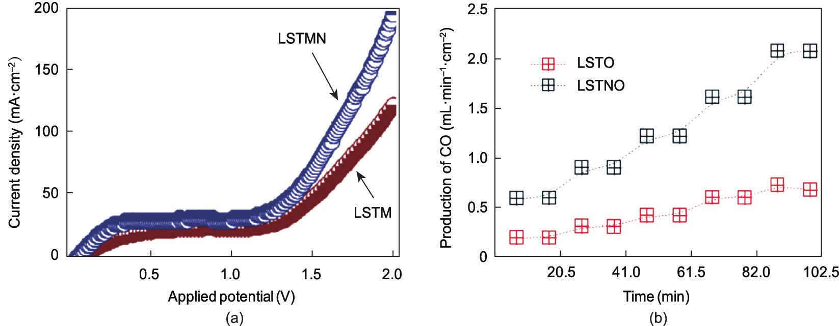
Fig. 7. (a) Electrochemical performance of an (La0.2Sr0.8)0.9(Ti0.9Mn0.1)0.9Ni0.1O3–δ (LSTMN) cathode before and after Ni exsolution (LSTM: (La0.2Sr0.8)(Ti0.9Mn0.1)O3–δ); (b) CO production for electrolyzers with LaxSr1–xTiO3+δ (LSTO) and (La0.3Sr0.7)0.9Ti0.95Ni0.05O3–δ (LSTNO) cathodes. (a) Reproduced from Ref. [54] with permission; (b) reproduced from Ref. [55] with permission.
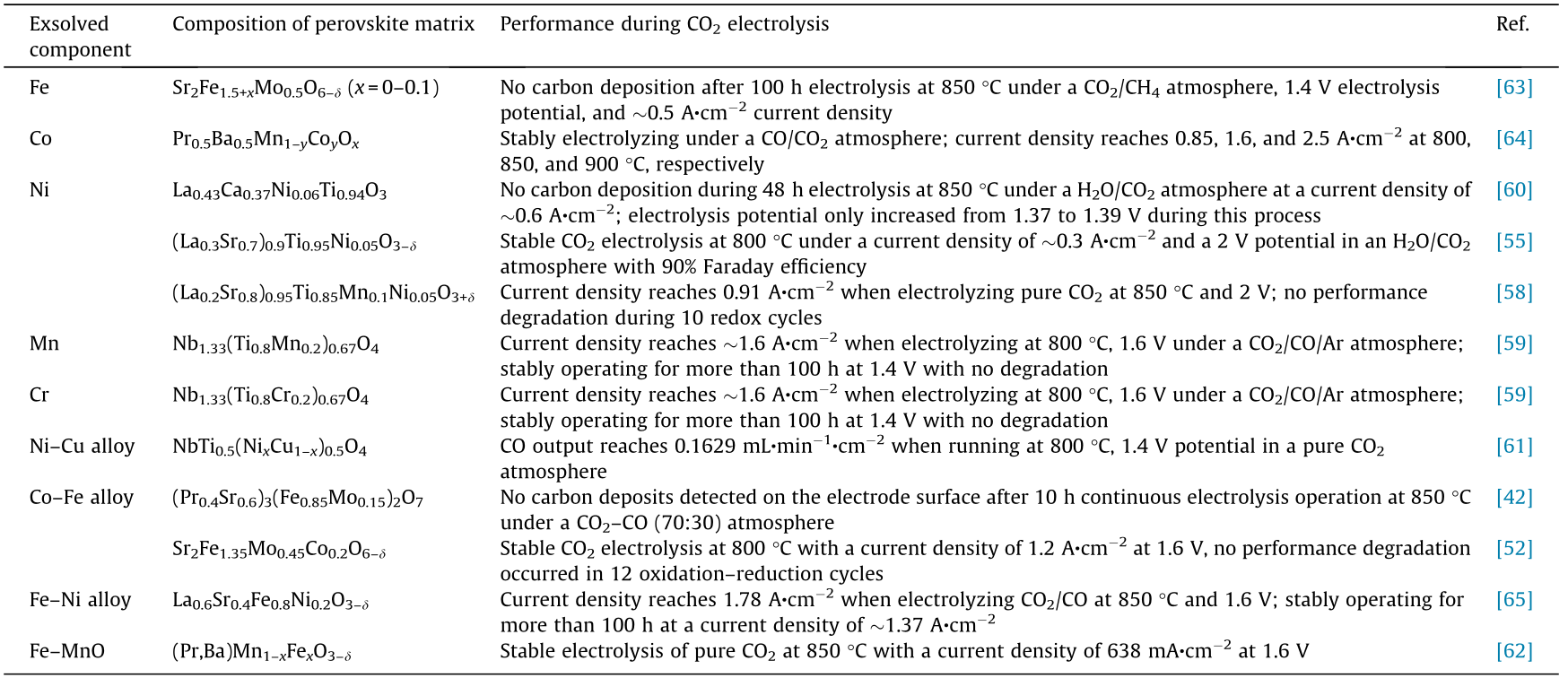
Many investigations have demonstrated that the metallic nanoparticles generated by in situ exsolution on the surface of a perovskite cathode have considerable electronic conductivity and electrocatalytic activity, as well as possessing excellent resistance against carbon deposition during CO2 electrolysis [38,41]. Using Raman spectroscopy, Liu et al. [42] investigated a (Pr0.4Sr0.6)3(Fe0.85Mo0.15)2O7 electrode with exsolved Co–Fe nanoparticles and demonstrated that no graphite signal was detected on the electrode surface after 10 h of electrolysis operation at 850 °C under a CO2–CO (70:30) atmosphere, while obvious graphite signals appeared on the surface of a conventional Ni–YSZ cathode under the same conditions (Fig. 8(a)). This finding suggests that exsolved Co–Fe nanoparticles possess much higher coke resistance than traditional SOEC cathodes. The coke resistance of Ni, Mn, Cr, Cu, and other exsolved metallic nanoparticles has also been confirmed in other SOEC cathode systems [58–61]. The performance of several cathodes with exsolved metallic nanoparticles during CO2 electrolysis or co-electrolysis is listed in Table 1 [42,52,55,58–65]. More specifically, Neagu et al. [23] proposed that these exsolved metallic nanoparticles typically have an ‘‘anchoring” effect in their original position, and that their structural stability and chemical stability are much higher than those of composite material systems prepared by infiltration methods. Zhao et al. [66] pointed out that the metallic nanoparticles anchored on the cathode surface both promoted the electrochemical reduction kinetics of CO2 and inhibited the carbon deposition process through rapid electron exchange, further accelerating the conversion from carbon on the surface into carbon-containing gas phase products (Fig. 8(b)). This finding explains the stability of these cathodes with exsolved nanoparticles during CO2 electrolysis.
《Fig. 8》
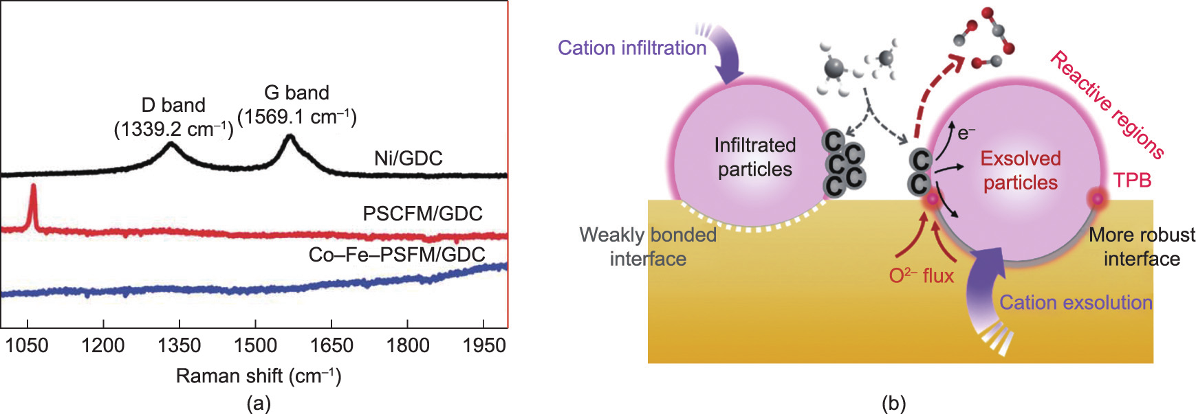
Fig. 8. (a) Raman spectra of Ni/GDC, Pr0.4Sr0.6Co0.2Fe0.7Mo0.1O3–δ (PSCFM)/GDC, and Co–Fe–(Pr0.4Sr0.6)3(Fe0.85Mo0.15)2O7 (PSFM)/GDC cathodes after testing; (b) comparison of fuel electrodes fabricated by infiltration and exsolution (TPB: triple phase boundaries). (a) Reproduced from Ref. [42] with permission; (b) reproduced from Ref. [66] with permission.
《Table 1》
Table 1 Performance of typical cathodes with exsolved metallic nanoparticles during CO2 electrolysis.
Although research on enhancing the electrochemical performance of perovskite electrodes by means of exsolved metallic nanoparticles has been widely confirmed in SOEC cathode systems, the mechanism or driving force of B-site exsolution remains unclear. Currently, it is generally accepted that the exsolution of B-site cations can be controlled by the distribution of the bulk/surface defects of the perovskite lattice and influenced by the external oxidation/reduction conditions [38,41,67]. When the perovskite lattice is reduced, oxygen vacancies are typically generated on the surface rather than within the bulk, while these surface defect sites tend to attract B-site transition metal cations within the bulk due to the charge effect. The existence of surface defects also decreases the barrier to the nucleation of metallic nanoparticles, thus accelerating the reduction and nucleation of B-site cations [23,41]. Such effects can continuously drive the B-site cations inside the crystal lattice to migrate to the outermost surface and can cause the exsolved metallic nanoparticles to continue to grow until a balance is reached [23,67]. In the future, with the development of in situ characterization technology and theoretical simulation methods, we expect to obtain a clearer understanding of the exsolution mechanism and kinetic process of B-site transition metal cations. This will allow us to obtain a better understanding of the precise control of cation exsolution behaviors, which will be useful for guiding the design of perovskite-based SOEC cathode materials with high electrochemical activity and high stability.
《3.2. Anode materials》
3.2. Anode materials
Regardless of water electrolysis or CO2 electrolysis, the oxygen evolution reaction (OER; 2O2– → O2 + 4e–) occurring at the oxygen electrode is one of the most critical steps in electrochemical conversion [68]. The evolution of oxygen molecules is a fourelectron process that possesses a high reaction energy barrier and relatively slow kinetics, and it often acts as the origin of the overpotential [69]. In order to improve the efficiency of the electrolysis reaction and reduce the polarization resistance and overpotential, anode materials are usually expected to possess the following properties: ① considerable electronic conductivity; ② considerable ionic conductivity; ③ abundant surface oxygen vacancies and a relatively low formation energy of oxygen vacancy; and ④ a porous morphology, which provides numerous channels for the diffusion and release of the generated O2 during electrolysis.
The most widely used SOEC anode materials are perovskitebased oxides, such as LSM, La1–xSrxCo1–yFeyO3–δ (LSFC), La1–xSrxCoO3–δ (LSC), and LSF, although these materials also have their own shortcomings in practice [2,70,71]. For example, LSM, which was commonly used as an SOEC anode material in the early years of this field, possesses high chemical and structural stability, as well as considerable electronic conductivity. However, its oxygen vacancy formation energy is relatively high and its ionic conductivity is low, resulting in insufficient electrocatalytic activity [38,72]. In comparison, LSC, which has considerable MIEC and electrocatalytic activity, possesses insufficient stability at high temperatures, and surface side reactions such as strontium (Sr) segregation are prone to occur; thus, the performance degradation issue is a bottleneck during long-term operation [38,72–75]. Therefore, achieving a balance between electrochemical activity and stability for anode materials is a key problem that needs to be solved in this field.
Studies have shown that decorating perovskite anode materials with precious metals or their compounds can simultaneously improve the electrocatalytic activity and the operational stability. For example, Li et al. [76] used a surface infiltration method to decorate an La0.5Ba0.25Sr0.25Co0.8Fe0.2O3–δ (LBSCF) porous anode with RuO2 nanoparticles (the anode loaded by RuO2 is referred to as LBSCF–Ru) and found that rapid material transfer and charge transfer could occur in the RuO2/perovskite interfacial region, contributing to a significant drop in polarization impedance. The electrolysis cell Ni–YSZ|YSZ|LBSCF–Ru based on this anode exhibited no detectable degradation during a pure CO2 electrolysis process at 850 °C and 1.6 V with a high current density of 2.26 A∙cm–2 for 90 h, thus demonstrating excellent durability for CO2 electrolysis. Song et al. [77] modified a YSZ anode with extrinsic gold (Au) and further fabricated a Ni–YSZ|YSZ|Au–YSZ electrolysis cell, which achieved a steady pure-CO2 electrolysis during 100 h of operation at 800 °C with no degradation. Such modification methods contribute to a step change in the development of confined electrodes with superior stability and activity for SOEC applications. However, the question of how to reduce the amount of precious metals in such electrodes in order to control the cost of anode manufacturing is still a problem that must be further considered in practical applications.
Aside from enhancing the electrocatalytic activity and chemical stability of electrode materials, it is crucial to improve the structural robustness and mechanical stability of the electrode. The OER occurring at the SOEC anode is a process in which the number of gas molecules increases. The commonly used sponge-like anodes generally contain a huge number of tortuous pores or closed pores. As a result, the gas diffusion property is usually unsatisfied, resulting in insufficient capability for the release of the generated oxygen. In particular, while operating at an elevated current density, increased oxygen production may lead to the formation of localized high-oxygen-pressure sites inside the anode, which causes delamination of the anode/electrolyte interface. This results in a sharp increase in the polarization resistance, endangering the long-term operational stability of the electrolysis cell [70,78]. To address this issue, optimizing the gas diffusion in the anode is crucial in order to enhance the stability against degradation under a high current density.
To reduce the gas diffusion resistance of an SOEC anode, a novel skeleton structure has been designed and remarkable results have been achieved. For example, Chen et al. [79] fabricated a microchannel-structured Gd0.1Ce0.9O2–δ (GDC) framework by means of a freezing-casting method and subsequently obtained an Sm0.5Sr0.5CoO3–Gd0.1Ce0.9O2–δ (SSC–GDC) porous anode via an infiltration–sintering method. The SSC–GDC|GDC|Ni–GDC cell based on this electrode was further demonstrated to have an extremely low polarization resistance of only 0.05 Ω∙cm2 at 600 °C, indicating excellent potential for electrolysis applications. Wu et al. [80] further optimized a frozen preparation technique for the oxygen electrode skeleton and successfully prepared a novel honeycomb-structured LSC–YSZ microchannel anode with regular morphology and extremely high pore density. The polarization resistance of this honeycomb-structured anode was only 0.0094 Ω∙cm2 at 800 °C, and the corresponding symmetrical cell could operate at a large current density of 2 A∙cm–2 with no detectable performance degradation during 6 h of operation. Based on these results, Li et al. [81] prepared an LSF–GDC|GDC–YSZ|Ni–GDC electrolysis cell with a microchannel anode and applied it in pure CO2 electrolysis. The cell exhibited good stability under a large current density of 2.5 A∙cm–2 at 800 °C, and no performance degradation was observed within 124 h of operation (Fig. 9) [81]. These fundamental research results provide guidance for the rational design of high-performance anodes for SOECs, as well as for the large-scale commercial application of SOECs in the field of CO2 electrolysis.
《Fig. 9》

Fig. 9. (a) SEM images of the channeled electrode; (b) oxygen release path in the bulk of the electrode; (c) electrolysis polarization curve of the electrolyzer. Reproduced from Ref. [81] with permission.
《3.3. Electrolyte materials》
3.3. Electrolyte materials
The electrolyte of an SOEC is positioned between the cathode and anode. Although it does not directly participate in the electrochemical reaction, the electrolyte still plays a vital role in determining the overall performance of the electrolysis cell [82,83]. In general, the function of the electrolyte is to conduct ionic charge carriers (e.g., oxygen ions), as well as blocking electronic conduction and preventing gas leakage. The following characteristics are thus typically required for the electrolyte materials of an SOEC: ① a relatively high ionic conductivity and almost no electronic conductivity under the operating conditions, to prevent short circuiting inside the electrolysis cell; ② a thermal expansion coefficient that is basically matched with those of both the hydrogen electrode and the oxygen electrode materials; ③ low reactivity with the hydrogen electrode and oxygen electrode materials; ④ structural durability and chemical stability under strong oxidizing and reducing conditions; and ⑤ a dense morphology to prevent the interdiffusion and leakage of gases on the anode side and cathode side [2].
Commonly used electrolyte materials for oxygen-ionconducting SOECs (known as O-SOECs) include doped zirconiumbased oxides (e.g., YSZ), cerium-based oxides (e.g., SDC), and several perovskite-structured oxides (e.g., LSGM) [2]. The relationship between conductivity, temperature, and thickness is shown in Fig. 10 [83]. It can be seen that increasing the operating temperature and reducing the thickness of the electrolyte are effective methods to enhance the electrical conductivity.
《Fig. 10》
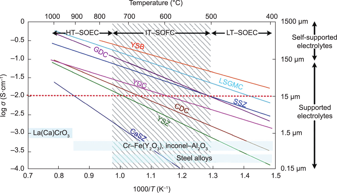
Fig. 10. Commonly used electrolyte materials for O-SOECs and their conductivity (HT: high temperature; IT: intermediate temperature; LT: low temperature; YSB: (Bi2O3)0.75(Y2O3)0.25; LSGMC: LaxSr1–xGayMg1–y–zCozO3; SSZ: (ZrO2)0.8(Sc2O3)0.2; YDC: Ce0.8Y0.2O1.96; CDC: Ce0.9Ca0.1O1.8; CaSZ: Zr0.85Ca0.15O1.85). Reproduced from Ref. [83] with permission.
YSZ is one of the most mature electrolyte materials for hightemperature SOECs due to its considerable ionic conductivity, excellent durability, and acceptable price [84,85]. Nevertheless, several challenges still exist, which have hindered its further industrial application [2,66]. For example, many researchers have suggested that there are typically numerous grain boundaries in a dense YSZ electrolyte layer, which possess an ionic conductivity 1–2 orders of magnitude lower than that of the YSZ grains [84,86]. In addition, it has been widely observed that, when operating at high temperatures, YSZ is likely to react with many anode compo LSC anode and a Ni–MgO–ceria cathode exhibited an area-specific resistance of only 0.6 Ω∙cm2 at 800 °C; moreover, the area-specific resistance of an LSGM-supported ten-cell stack was only 1 Ω∙cm2 at 800 °C. Despite these advantages, LSGM electrolytes tend to react with metallic Ni to generate an inactive LaNiO3 phase, so modifications on anodes are still required to avoid such side reactions [82]. Fop et al. [92] developed a novel hexagonal perovskite derivative, Ba3MoNbO8.5, which showed excellent stability and exhibited a relatively high oxide ionic conductivity of 2.2 × 10⁻³ S∙cm–1 at 600 °C. Hopefully, the development and utilization of these novel electrolytes can significantly enhance the electrochemical performance of SOECs, in what could be a new direction for the future development of SOEC components.
Another research direction for optimizing SOEC electrolytes is to reduce its thickness, as a thin and stable electrolyte layer can significantly reduce the ohmic loss of electrolysis and greatly improve the electrolysis performance [11]. In the future, the development and application of new preparation technologies such as molecular beam epitaxy (MBE), atomic layer deposition (ALD), and pulsed-laser deposition (PLD) [85,93] may bring revolutionary changes in this field, greatly accelerating the pace of the large-scale industrialization of CO2 high-temperature electrolysis technology.
《4. SOEC-coupled chemical carbon-reduction techniques》
4. SOEC-coupled chemical carbon-reduction techniques
It can be concluded from the aforementioned discussion that the components involved in SOECs typically possess the characteristics of affordability, structural stability, and performance stability under elevated temperature and a carbon-containing atmosphere. Such properties will not only contribute to the large-scale promotion of SOEC technology in the future but also make the device suitable for relatively complex chemical synthesis systems. By integrating the SOEC high-temperature electrolysis process with several chemical synthesis processes, various fuels or chemical raw materials can be produced, which is a promising route for taking advantage of SOECs.
《4.1. SOEC modular design and scale-up》
4.1. SOEC modular design and scale-up
In order to meet the different scale demands for industrial application, modular designs of SOEC systems are necessary. Through modular design, single cells with uniform size can be arranged together to form an SOEC stack, and several stacks can be further assembled into an SOEC module (Fig. 11) [94]. In general, an increase in the number of modules can lead to enhanced surface area, resulting in elevated production capacity. Therefore, a modular design can enlarge the size of SOECs and promote their industrial application. It also increases the flexibility and reliability of SOEC systems.
《Fig. 11》

Fig. 11. Illustration of arranging single cells of a uniform size together to form stacks and modules. Reproduced from Ref. [94] with permission.
Here, it should be noted that SOEC systems operating in complex environments should include many necessary components in addition to the stack itself. For example, a heat management system can recover the heat contained in outlet products and therefore improve the overall electrolysis efficiency; a purification system can adjust the composition of the inlet gas and remove the impurities that may attenuate the stack; and an automatic control system can remotely control the SOEC module [2,4]. These system accessories have also undergone tremendous recent development; however, instability and unreliability still exist, and the unreliability of these system components has actually become the most common reason for system breakdown [4]. Thus, in future, the development and optimization of these system accessories are still necessary in order to further improve the operational stability and reliability of SOEC stacks and modules.
《4.2. SOEC application scenarios in the chemical industry》
4.2. SOEC application scenarios in the chemical industry
In application scenarios involving SOECs coupled with processes in the chemical industry, one of the most well-known technical paths is the production of CO/H2 synthesis gas by coelectrolyzing the high-temperature waste gas generated in chemical processes, and then converting the synthesis gas into methane, ethylene, liquid hydrocarbons, alcohols, and other chemical raw materials through the Fischer–Tropsch synthesis reaction [1,2,14]. This route can use the waste gas and waste heat generated by the chemical process effectively; it can also convert CO2 into liquid carbon-containing products, which is of great significance for achieving the goals of a carbon peak and carbon neutrality. For experimental verification, Chen et al. [14] designed an SOECcoupled Fischer–Tropsch synthesis device consisting of a tubular SOEC high-temperature electrolysis unit (an LSM–YSZ|YSZ|Ni–YSZ tubular electrolysis cell, operating at ~800 °C) and a Fischer– Tropsch synthesis unit (operating at ~250 °C), as illustrated in Fig. 12. When the intake air was about 15 mL∙min–1 CO2/H2 (CO2:H2 = 1:6) and the relative humidity was 20%, the methane yield at the outlet was 0.84 mL∙min–1 , and the CO2 conversion rate reached 64%. Furthermore, Luo et al. [95] prepared an LSGM-based tubular SOEC that achieved one-step CH4 production, with a high CO2-to-CH4 conversion ratio of 98.7%. More recently, Lee et al. [96] developed a six-cell flat-tubular Ni–YSZ|YSZ–GDC|LSCF–GDC SOEC bundle with a total active area of 240 cm2 , which achieved durable co-electrolysis for a continuous 500 h at a H2O/CO2 ratio of 2 at 800 °C. These results preliminarily demonstrate the feasibility of this technology path at the laboratory scale.
《Fig. 12》

Fig. 12. Schematic diagram of direct methane synthesis from CO2–H2O co-electrolysis in a unit combining an SOEC and a Fischer–Tropsch (F–T) reactor. Reproduced from Ref. [14] with permission.
In recent years, due to continuous development and optimization, CO2 high-temperature electrolysis technology based on SOECs is ready for industrial scale-up, and its scaling up has been proceeding rapidly. In 2017, Küngas et al. [97] from Haldor Topsøe A/S reported the world’s first commercial CO2 electrolysis system (eCOs), which can deliver more than 10 normal cubic meters (Nm3 ) CO per hour at 99.995% purity. Two years later, they further provided the test data of their stacks with improved components: Under the conditions of 750 °C and –70 A, a single SOEC stack with 2.2 Nm3 ∙h–1 CO production capability can operate for more than 5000 h with no detectable degeneration [98]. Based on these developments, Haldor Topsøe A/S was prepared to develop several commercial plants that would be able to produce 96 Nm3 ∙h–1 CO at > 99.95% purity in the next two years [97,98]. In 2019, Posdziech et al. [99] from Sunfire GmbH developed a co-electrolysis demonstration system that integrated three stacks to produce syngas (Fig. 13). The system could be fed by different H2O/CO2 mixtures, and the maximum production rate of syngas was 4 Nm3 ∙h–1 with 10 kW inlet power. In 2020, Dannesboe et al. [100] from both Aarhus University and Haldor Topsøe A/S reported that they had successfully combined an SOEC system with the downstream synthesis process for upgrading biogas to pipeline quality biomethane in a pilot plant yielding 10 Nm3 ∙h–1 . This system had been running continuously for more than 2000 h, the power consumption of the SOEC stack was about 3.07 kW∙h∙Nm–3 H2, and the power utilization efficiency reached approximately 80%[101]. Recently, the New Energy and Industrial Technology Development Organization in Japan declared that a total of about 4.5 billion JPY will be invested in 2020–2024 to develop the integrated production technology of CO2 electrolysis and the Fischer–Tropsch synthesis to produce liquid synthetic fuels (gasoline, diesel, aviation fuel, etc.) [4].
《Fig. 13》
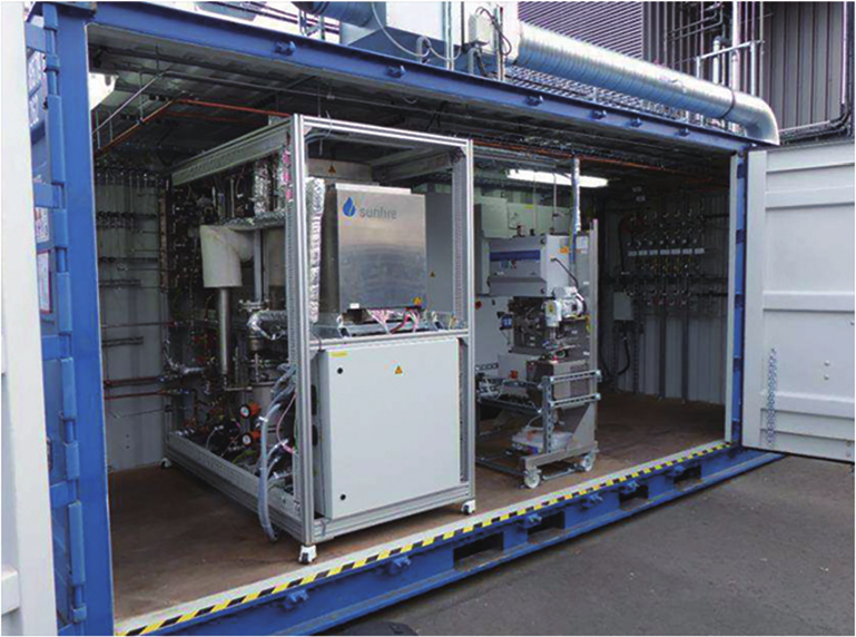
Fig. 13. A co-electrolysis system demonstration developed by Sunfire GmbH. Reproduced from Ref. [99] with permission.
In addition to producing hydrocarbon fuels, researchers have developed SOEC technology for the precise synthesis of specific small molecules, such as the directional synthesis of C2H4 and NO, as shown in Fig. 14 [1]. These small molecules can be further subjected to catalytic oxidation, polymerization, or other reactions to obtain a series of high-value-added products such as fertilizers, synthetic resins, and synthetic rubbers.
《Fig. 14》

Fig. 14. Schematic diagram of various chemical processes based on SOEC reactors. Reproduced from Ref. [1] with permission.
It is accepted that the production of small molecules by means of SOECs has unique advantages in terms of overall efficiency, because SOECs can be operated at a relatively high current density (especially for CO2 electrolysis), which represents high output [4]. In addition, the integration of SOECs with several chemical production processes (e.g., synthesis of methane, methanol, and ammonia) has many advantages from the perspective of energy utilization (Fig. 15) [4]. It should be noted that all the above processes involve exothermic reactions; thus, the heat released can be utilized to produce the steam needed as feedstock for the SOEC, which further maximizes the use of energy and has a substantial synergistic effect. In addition, for coupling with ammonia synthesis, the distinctive capability of the SOEC to function as an oxygen separation membrane is taken advantage of; the use of heat in lieu of power can be harnessed to eliminate the need for an expensive air separation unit to provide nitrogen (Fig. 15(c)). These synthetic methods indicate the possibility of overturning the traditional fabrication route of chemical products mainly derived from petroleum. In the future, with the further development of renewable energy power generation technology and the price reduction of renewable electricity, such oil-free SOEC-coupling chemical preparation and synthesis processes are expected to become novel technical routes for the chemical industry.
《Fig. 15》
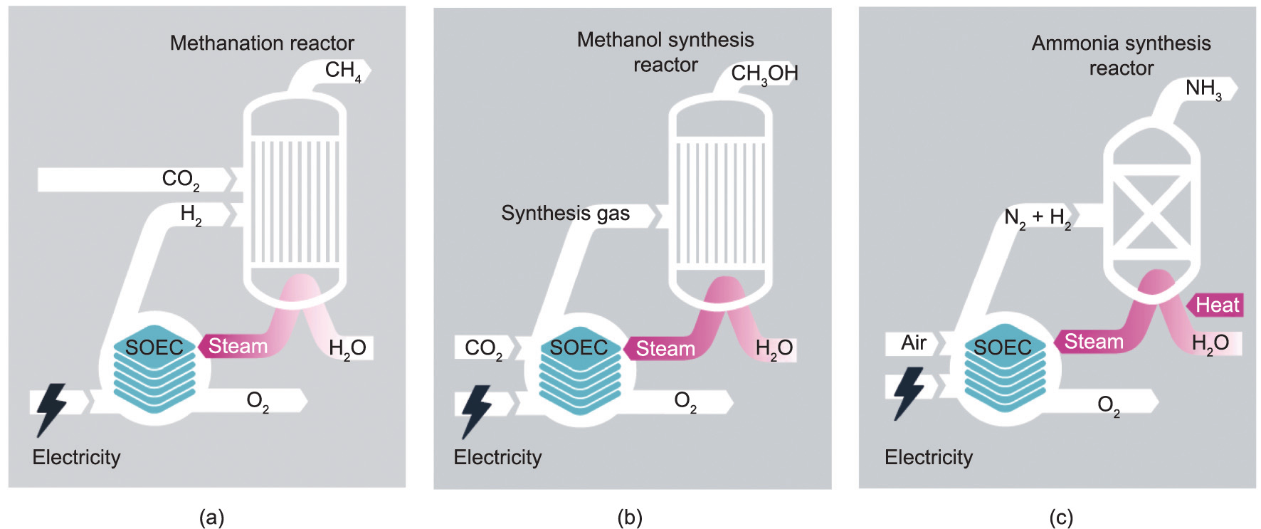
Fig. 15. Schematic diagram of an SOEC coupling chemical synthesis and carbon reduction process: (a) methane synthesis; (b) methanol synthesis; and (c) ammonia synthesis. Reproduced from Ref. [4] with permission.
《4.3. Challenges and future research directions》
4.3. Challenges and future research directions
Although significant progress has been made in this field, several technological achievements must be made in order to realize the large-scale application of high-temperature CO2 electrolysis. These include: ① the development of highly active and stable cell components; ② large-scale CO2 collecting and purification technology; ③ highly efficient heat management systems for high temperature SOEC stacks; and ④ separation and purification technology for obtaining single-component outlet gas [2,102]. Thus far, several solutions have been proposed for enhancing the performance of SOEC-based CO2 conversion systems [103–107]. For example, given that the feed gases of CO2 produced from natural gas or coal gasification may contain impurities such as H2S, a series of sulfur-resistant materials have been applied as SOEC cathodes, and various inlet gas pretreatment systems have been developed to mitigate electrode poisoning [2,105]. In addition, to improve the thermal efficiency of the conversion systems, the heat released during an exothermic chemical synthesis process has been designed to be utilized in the form of latent or sensible heat [103]. Moreover, to obtain concentrated CO2 from air or industrial plants, alkaline chemical absorbents have been proposed as intermediates for large-scale CO2 storage and release [107]. In the future, with the development and application of these related technologies, the reliability and operational stability of hightemperature CO2 electrolysis devices can be further enhanced.
Nevertheless, several economic issues are still presented by SOEC technology, including: ① high operation and maintenance costs due to the degradation issues of the cell components; ② high production costs due to the high electricity consumption; and ③ high construction costs due to a lack of standardized manufacturing techniques and the limited scale of currently existing SOEC plants [1,2]. To address these challenges, we suggest the following areas as future research directions:
(1) Exploring cheap cell component materials with high electrochemical properties and considerable stability, thus mitigating material degradation and extending the lifespan of the stack. Moreover, fundamental research focusing on the degeneration mechanism of SOEC components in in situ environments is necessary for the rational design of more durable cell materials and stacks.
(2) Developing single cells with novel structures (e.g., honeycomb-structured microchannel electrodes) to further facilitate the kinetics of the elementary reaction steps (including gas adsorption, electron transfer, ion diffusion, etc.) of hightemperature electrolysis, as well as promoting the systematization and scaling-up of single cells into stacks and modules, while ensuring air tightness and operating stability.
(3) Exploring the coupling mode of high-temperature electrolysis and renewable energy, which mainly involves developing SOEC stacks and modules that can operate continuously and stably under the intermittent electricity input from renewable energy sources.
Such improvements are expected to significantly reduce the operating costs of SOEC and broaden its application scenarios, as well as further promote SOEC-coupled chemical industry carbon neutralization solutions.
《5. Conclusion and outlook》
5. Conclusion and outlook
CO2 high-temperature electrolysis technology based on SOECs holds great importance for achieving China’s goals of carbon emission reduction, peak carbon emission, and carbon neutralization. By consuming electricity, SOECs can directly convert CO2 (or CO2/ H2O) into CO (or hydrocarbon fuels), thereby realizing the recycling utilization of CO2. Great progress has been made in CO2 high-temperature electrolysis technology at the laboratory and pilot stages, although the large-scale industrial application of this technology still needs further development. The main challenges include how to improve the operating efficiency and stability at a high temperature and high current density, and how to promote the systematization and scaling-up of single cells into stacks and modules while ensuring long-term durability. To address these challenges, it is essential to explore low-cost cell component materials with excellent electrochemical properties and considerable stability, develop cells and stacks with novel structures, and explore the coupling mode of high-temperature electrolysis and renewable energy. In the future, fundamental research on hightemperature electrochemistry requires further effort, and the application of advanced in situ characterization methods and simulation analysis methods should be accelerated to provide guidance for the rational design of materials suitable for highperformance CO2 electrolysis. Furthermore, key accessories for high-temperature CO2 electrolysis systems should be developed, including power supplies, gas purification systems, gas circulation systems, and temperature-control systems. Meanwhile, comprehensive simulations and experimental studies should be accelerated to verify the economic and technical feasibility of SOECcoupled chemical carbon reduction technology, thereby laying down a theoretical and experimental basis for the establishment of a large-scale CO2 recycling utilization industrial chain.
《Compliance with ethics guidelines》
Compliance with ethics guidelines
Yifeng Li, Longgui Zhang, Bo Yu, Jianxin Zhu, and Changjiang Wu declare that they have no conflict of interest or financial conflicts to disclose.


 京公网安备 11010502051620号


