
《1. Introduction》
1. Introduction
《1.1. Research background of the train-bridge interaction system》
1.1. Research background of the train-bridge interaction system
With the development of high-speed trains, the dynamic performance of the high-speed railway bridge becomes more important. Problems concerning the structural safety, dynamic bearing capacity, and service reliability of bridges used by high-speed trains have attracted the attention of engineers and researchers. A train-bridge dynamic interaction analysis can be applied in order to evaluate the safety of the bridge and of the running train. When designing high-speed railway bridges, it is necessary to study the train-bridge dynamic interaction in order to ensure that the bridge and train dynamic parameters are within the safe range.
Research on train-bridge dynamic interaction analysis originated in the 1840s. This problem, however, is very complicated, as many factors must be considered, including vehicle parameters, train speed, bridge form and span, bridge stiffness and damping, the track structure on the bridge, wheel/rail interaction, rail/ bridge interaction, and so forth. In addition, random factors such as wheel irregularity, track geometric error, and wheel hunting movement make the mechanical model more complex. Therefore, previous studies have had to adopt some simplifications. In recent decades, with the application of high-speed computers and advanced numerical methods, the dynamic analysis of train-bridge interactions has become both easier and more helpful to railway engineering.
The study of the train-bridge dynamic interaction involves various specialties such as bridge engineering, vehicle dynamics, track engineering, transportation engineering, earthquake engineering, wind engineering, vibration control, and others, as shown in Fig. 1.
《Fig. 1》
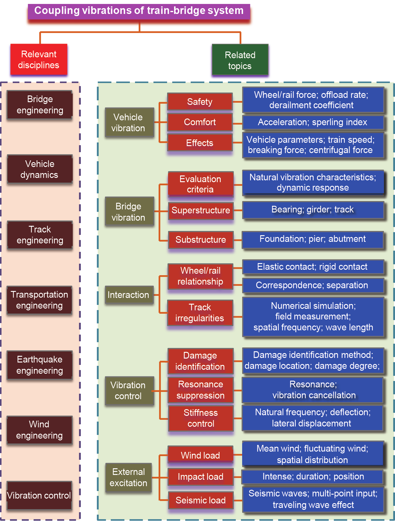
Fig. 1. The research system of train-bridge dynamic interactions.
《1.2. Methods for studying the train-bridge dynamic interaction system》
1.2. Methods for studying the train-bridge dynamic interaction system
Research methods for the train-bridge dynamic interaction include theoretical analysis, numerical simulation, and experimental study.
(1) Theoretical analysis: It refers to the analytical method. This method expresses each part of the train-bridge system by the theoretical model, which relies on theoretical derivation via mathematics and mechanics. Not only can this method help researchers to better understand the problem in theory, but it can also provide references for the validation of numerical simulation results. However, as a train-bridge system analysis is complex, various simplifications of the actual situation should be made for theoretical analysis, including geometry and material property and boundary conditions. As a result of such simplifications, no completely accurate analytical results exist. Even in ideal conditions, a completely closed-form solution is difficult to obtain for certain complex conditions, unless approaches such as the numerical integration of an analytic method are adopted.
(2) Numerical simulation: With the development of computer technology, various numerical methods have become highly effective for simulating the train-bridge dynamic interaction. These methods play an increasingly important role in this field. Widely used numerical simulation methods include the finite element method, the boundary element method, and some mixed methods. Due to the need to calculate conditions, a numerical simulation must use some approximation assumptions in the modeling. The most important problem when modeling is how to validate the model experimentally. The numerical simulation method is widely used due to the complexity of actual bridges and train vehicles and to the time-varying characteristics of a moving load.
(3) Experimental study: This is one of the main means for train-bridge dynamic interaction analysis. Before the finite element method was used in analyses, experimental testing was the main way of studying the train-bridge dynamic interaction. Experiential formulas and theory were summarized from in situ tests and used to guide bridge design. Some vibration tests were done for a series of new types of structures or for high-speed running conditions. Based on these test results, train-bridge interaction models are set up. The main structural vibration factors for the bridge spans are then decided based on a comparison of the results of simulations and testing.
Experimental study is often used in train-bridge interaction analysis. Since it is difficult to simulate real wheel/rail interaction relations using a small-scale model test, field measurements are often used in order to study the actual working conditions of a bridge under dynamic loads. With different types of bridge structures, bridge spans, and vehicle performances, a large number of repeated experiments must be done to determine new dynamic parameters; however, these experiments can be a waste of time if they do not reveal the inherent law further. Thus, simple tests are often constrained by many restrictions.
On the other hand, it is difficult to solve the problem using only theoretical analysis. Bridge vibration under a train load is a very complicated problem in which many factors must be taken into account, including the masses of car bodies and bogies; the effect of dampers and springs; the train speed; the masses, stiffness, and damping of the beam spans and piers; the structural type and dynamic performance of the track on the bridge; the dynamic interactions between wheel and rail and between rail and beam; and so forth. In addition, wheel irregularity and the geometric and dynamic irregularities of the tracks create very complicated mechanics within the system. A train-bridge dynamic interaction model is limited by the calculated measurements. For example, vehicle loads are simplified into a series of moving constant forces or into a deterministic simple harmonic excitation. Of course, the most important issue with simplified models is experimental validation.
《1.3. Motion equations of the train-bridge interaction system》
1.3. Motion equations of the train-bridge interaction system
Based on structural dynamics theory, both the train subsystem and the bridge subsystem are regarded as a multi-degree-offreedom (MDOF) system, and the motion equations of the trainbridge interaction system can expressed as follows [1–3]:
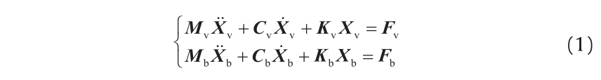
where, Mv, Cv, and Kv are the global mass, damping, and stiffness matrices of the train subsystem, respectively; Mb, Cb, and Kb are the global mass, damping, and stiffness matrices of the bridge subsystem, respectively; Xv and Xb are the displacement vectors of the train subsystem and the bridge subsystem, respectively; and Fv and Fb are the force vectors of the train subsystem and the bridge subsystem, respectively.
Excitations on the system can be divided into several categories, as shown in Fig. 2, including track irregularity, structure deformation, wind load, collision load, structural damage, foundation scouring, and earthquake. The mathematical expressions of these excitations in Eq. (1) are introduced below.
《Fig. 2》
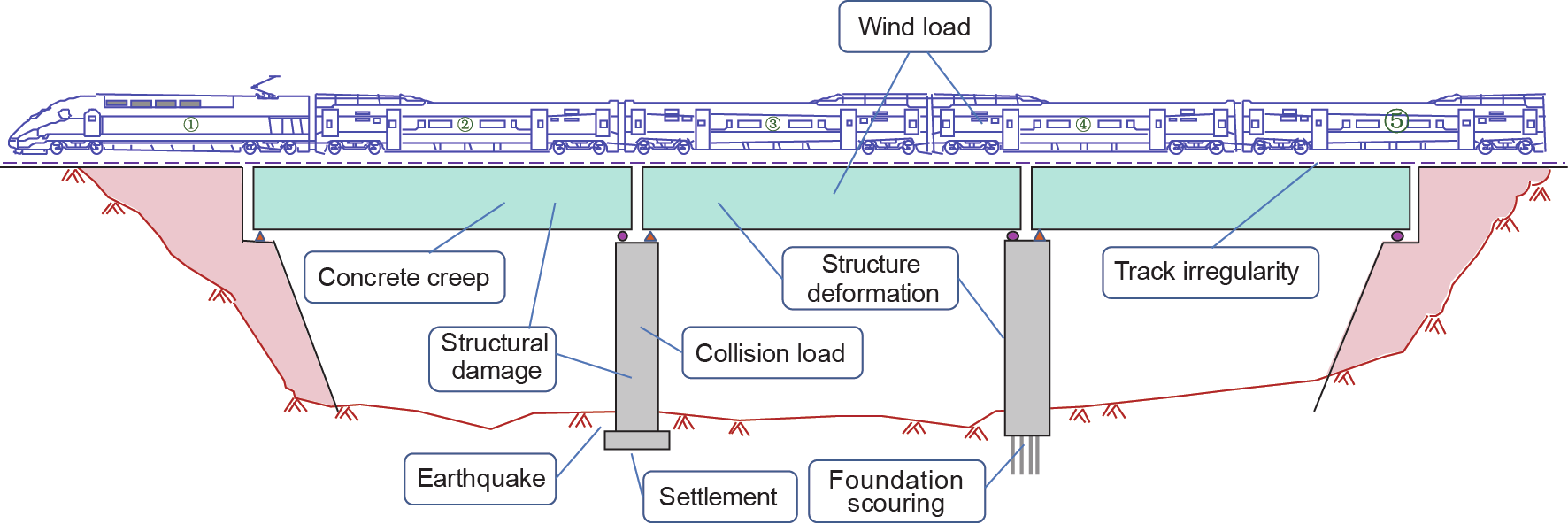
Fig. 2. The problem of train-bridge interactions.
(1) Track irregularity: Track irregularity is one of the main excitations for the train-bridge interaction system. The interaction force between the vehicle subsystem and the bridge subsystem is not only the function of track irregularity, but also the function of the motion state (Xv and Xb) of the train vehicle and the bridge, due to the coupling relationship between them. Assuming the track irregularities to be i, the motion equation of the train-bridge interaction system can be expressed as follows [4,5]:

In the mathematical form, the train subsystem and the bridge subsystem in Eq. (1) are independent of each other, while in the simultaneous Eq. (2), the two subsystems are coupled through Fvi and Fbi, thus establishing the mathematical expressions of Fvi and Fbi as the key point for the dynamic analysis of a train-bridge interaction. All of these mathematical expressions depend on the wheel/ rail relationship assumption and the value track irregularity i.
(2) Structure deformation: This includes the quasi-static deformations induced by creep effect, thermal load, and foundation settlement, which may cause geometry changes in the tracks on the bridge [6–8]. Quasi-static deformations can be regarded as an additional track irregularity acting on the train-bridge system. Assuming the additional track irregularity to be ia, Eq. (2) can be expressed as follows:

(3) Wind load and collision load: In the dynamic analysis of a train-bridge system, when neglecting the self-excitation forces of the wind on the train and on the bridge or neglecting the dynamic interaction between the collider and the bridge during a collision, the wind load or collision load can be regarded as the external forces on the train and the bridge. When the calculation conditions are given, the time histories of these external forces are known; which is a function of the acting location and duration of the loads on the train and the bridge. Assuming the external force vectors of the train subsystem and of the bridge subsystem to be Fve(t) and Fbe(t), respectively, Eq. (2) can be expressed as follows [9–11]:

(4) Structural damage and foundation scouring: Structural damage and foundation scouring of the bridge can be regarded as a decrease of the global stiffness. Structural damage induces the reduction of the damaged section or of the material elastic modulus, while foundation scouring decreases the restraint stiffness at the bottom of the piers. Considering the above effects, the motion equations of the train-bridge system can be expressed as follows [12,13]:

where, Kbd is the reduced amount of global stiffness after structural damage.
(5) Earthquake: Earthquakes can be regarded as a set of known time histories of ground motion at the earthquake input points (i.e., the bottom of the bridge pier, the bottom of the pile caps, or foundations) of the bridge subsystem [14–16]. Normally, the seismic responses at different foundations are inconsistent, resulting in the problem of non-uniform seismic excitation.
Simultaneous equations between Eq. (1) and the given seismic histories can be established to solve the dynamic response. The motion equations of the train-bridge system under seismic action can be expressed as follows:

where, Xs,  , and
, and  are the displacement, velocity, and acceleration vectors at the earthquake input points, respectively; and Tbs is the transform matrix from the bridge displacement vector Xb to the displacement vector at the earthquake input points Xs.
《2. Train-bridge interaction model》
2. Train-bridge interaction model
《2.1. Train model》
2.1. Train model
The train subsystem consists of several vehicle elements, and each vehicle element is an MDOF vibration system composed of the car body, bogies, wheel sets, and spring-damper suspension systems, as shown in Fig. 3.
《Fig. 3》
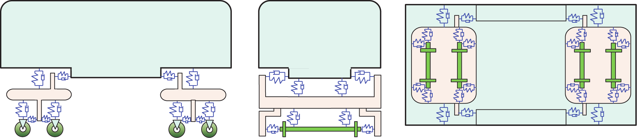
Fig. 3. The vehicle element model.
In the train model, the vehicles are regarded as independent and the coupling effect between them is ignored. In a high-speed train, each vehicle has two suspension systems. The springs and dampers between the bogies and wheels are the primary suspension system, and those between the car body and bogies are the secondary suspension system. In most research, viscous dampers are used for the vehicle element. Because the train-bridge interaction system is solved with a step-by-step method, other forms of damping can also be used. Thus, the global mass, damping, and stiffness matrices are derived by multi-rigid-body dynamics, as in Refs. [1–5].
《2.2. Bridge model》
2.2. Bridge model
The motion equations for the bridge subsystem are established with the following assumptions:
(1) There is no relative displacement between the track and bridge deck, and the elastic effect of the track system is also neglected.
(2) The modes of the bridge deck are consistent with the modes of the bridge nodes, which can be calculated by interpolating the mode-shape functions at the nodes.
(3) The deformation of the cross-section is neglected.
《2.3. Wheel/rail interaction force》
2.3. Wheel/rail interaction force
The key problem in the dynamic analysis of a train-bridge system is the wheel/rail interaction relation, which defines the relative movement and interaction force between the wheel and the rail. It can be divided into the following two classes:
(1) The wheel/rail interaction force is a function of wheel/rail relative movement; examples include the Hertz contact theory and the Kalker linear creep theory and its modification.
(2) The wheel/rail interaction force is a function of rail movement; examples include the vertical wheel/rail corresponding assumption and the wheel/rail hunting assumption.
In this paper, the vertical wheel/rail corresponding assumption and the lateral Kalker linear creep theory are adopted.
The vertical wheel/rail corresponding assumption defines no relative movement between the wheel and the rail in the vertical direction. Thus, the vertical wheel/rail force is determined by the motion status of the wheel and the rail. According to this assumption, the wheel set and the rail have the same dynamic displacement, as well as the same dynamic velocity and acceleration. Therefore, the additional velocity and acceleration of the wheel set by the track irregularity can be calculated using the differential form:
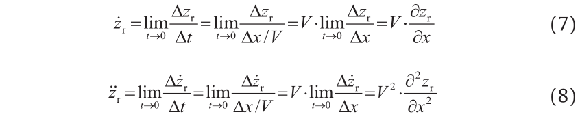
where, zr stands for any item of track irregularity; t is time; x is the coordinate of track in x direction; and V is the train speed. In this case, the vertical wheel/rail force is composed of the spring force and damping force from the primary suspension, the inertia force of the wheel set, and the static axle load of the vehicle.
The Kalker linear creep theory was proposed in 1967, and solved the problem of three-dimensional steady rolling contact in the elliptical contact zone. This theory has been widely adopted to simulate the lateral wheel/rail relationship [2,4]. Based on Kalker linear creep theory, the wheel/rail creep force can be expressed as follows:

where, Fx and Fy are the creep forces in the longitudinal and lateral directions, respectively, and FΨ is the creep moment around the vertical direction. f11, f22, and f33 are the creep coefficients related to the longitudinal, lateral, and vertical directions, which are the functions of the wheel/rail relative motion, the flange shape, and the Young’s modulus of the material, respectively. ξx, ξy, and ξψ are the creep ratios in x, y, and z directions.
《2.4. Solution of train-bridge interaction system equations》
2.4. Solution of train-bridge interaction system equations
The inter-system iteration method is used to solve the trainbridge interaction equations. Its procedures are shown in Fig. 4 and described below:
Step 1: Solve the train subsystem by assuming the bridge subsystem to be rigid, setting the bridge motion to zero, and using the track irregularities as the excitation, in order to obtain the time histories of the wheel/rail forces/moments for all wheel sets.
Step 2: Solve the bridge subsystem by applying the wheel/rail interaction force histories obtained in the previous iteration loop (or Step 1) on the bridge deck, in order to obtain the updated time histories of the bridge deck movement at all joints.
Step 3: Solve the train subsystem by combining the updated bridge deck movements obtained in Step 2 with the track irregularities as the updated system excitation, in order to obtain the updated time histories of the wheel/rail forces/moments for all wheel sets.
Step 4: Calculate the errors between the updated wheel/rail interaction force histories of all the wheel sets obtained in Step 3 and those in the previous iteration loop (or Step 1) for the convergence check.
《Fig. 4》
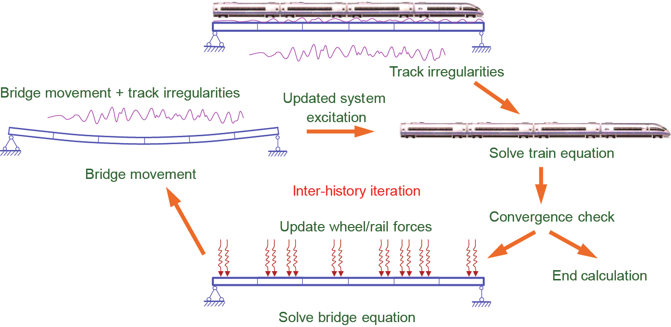
Fig. 4. Procedure for the inter-history iteration.
The main advantage of inter-history iteration is that any commercial structural analysis software can be used for the bridge subsystem and will be equivalent in solving it, making the analysis easier and more accurate. For most cases, the converged result can be obtained within several iteration steps. For other cases, however, it may be difficult to obtain the converged result owing to high-frequency components in the vibration. A problem such as this can be partly solved by using a smaller time-step or a larger threshold in the convergence check, or by adopting numerical dissipation to reduce the high-frequency vibration artificially.
《3. Case study》
3. Case study
The case study concerns a CRH380BL high-speed train running through a standard-design bridge of a high-speed railway line in China. The bridge consists of 10 successive 31.5 m-span double track pre-stressed concrete beams, as shown in Figs. 5 and 6. The total length of each beam is 32.6 m, and each beam is 12 m in top width, 5.5 m in bottom width, and 3.05 m in height. The analytical part of the bridge contains nine circular sectional piers that are 4 m in diameter and 15 m in height. Thus, the first-order vertical, lateral, and torsional natural frequencies of the beam are 6.40 Hz, 17.68 Hz, and 18.96 Hz, respectively.
《Fig. 5》

Fig. 5. Bridge concerned in case study (unit: m).
《Fig. 6》
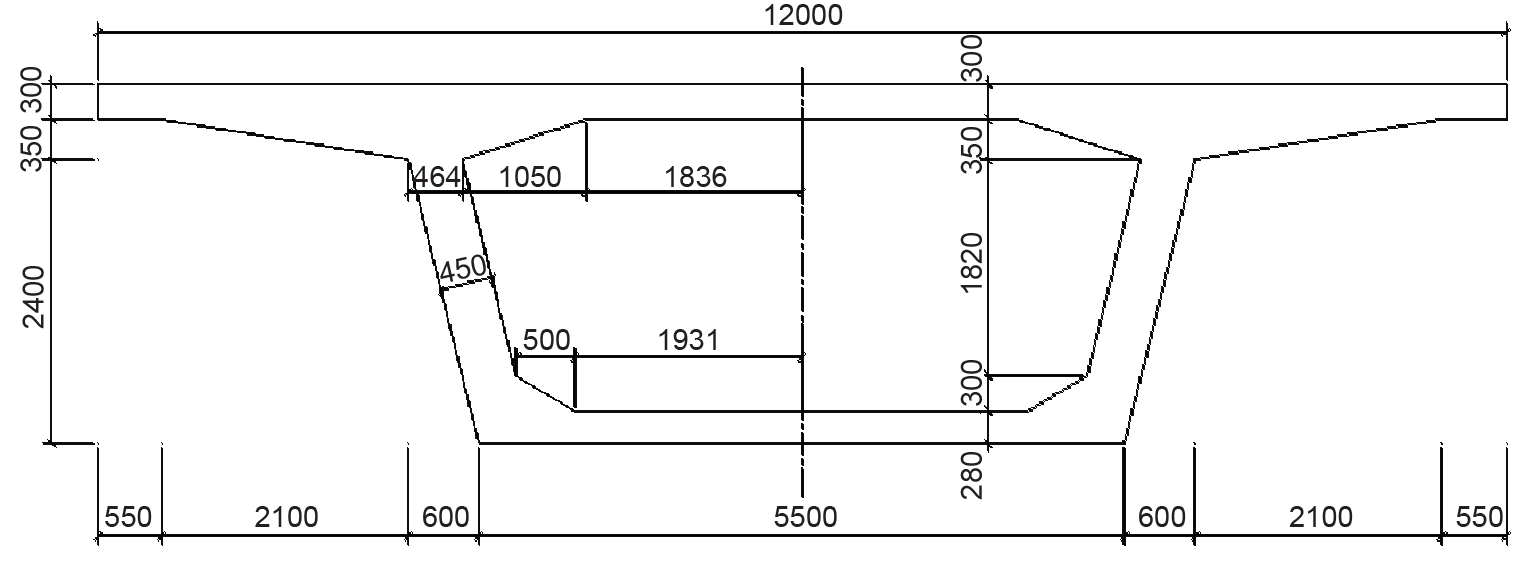
Fig. 6. Cross-section of beam (unit: mm).
The CRH380BL train consists of 16 cars, organized in two groups of MTMTTMTM. The axial loads for both the motor cars (M) and the trailer cars (T) are 152 kN, and the dimensions of the train are shown in Fig. 7.
《Fig. 7》
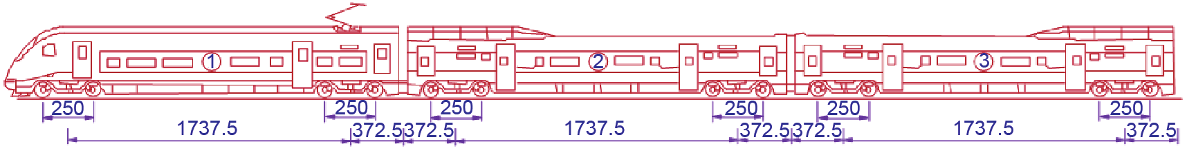
Fig. 7. Composition of the CRH380BL train (unit: cm).
Track irregularity samples transformed from the German low-disturb spectrum are used as the system exciter. Their spatial domain curves are shown in Fig. 8.
《Fig. 8》
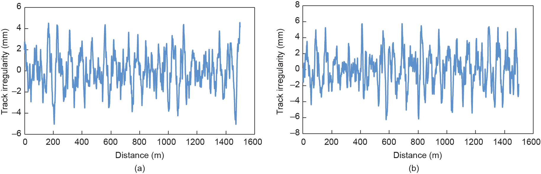
Fig. 8. Track irregularities transformed from the German low-disturb spectrum. (a) Vertical irregularity; (b) lateral irregularity.
Based on the inputted information mentioned above, the dynamic responses of the vehicle and of the bridge subsystems are obtained for speeds ranging from 200 km·h–1 to 400 km·h–1. The histories of the vertical and lateral displacements at the middle of the 6th span, the vertical and lateral accelerations at the middle of the 6th span, the vertical and lateral wheel/rail forces of the 1st wheel set, and the vertical and lateral accelerations of the 1st car body are shown in Figs. 9–12.
《Fig. 9》
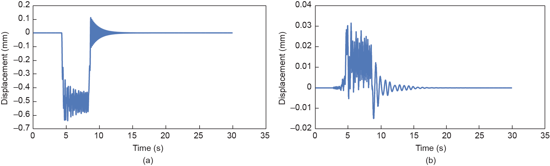
Fig. 9. Displacements at the middle of the 6th span. (a) Vertical history; (b) lateral history.
《Fig. 10》
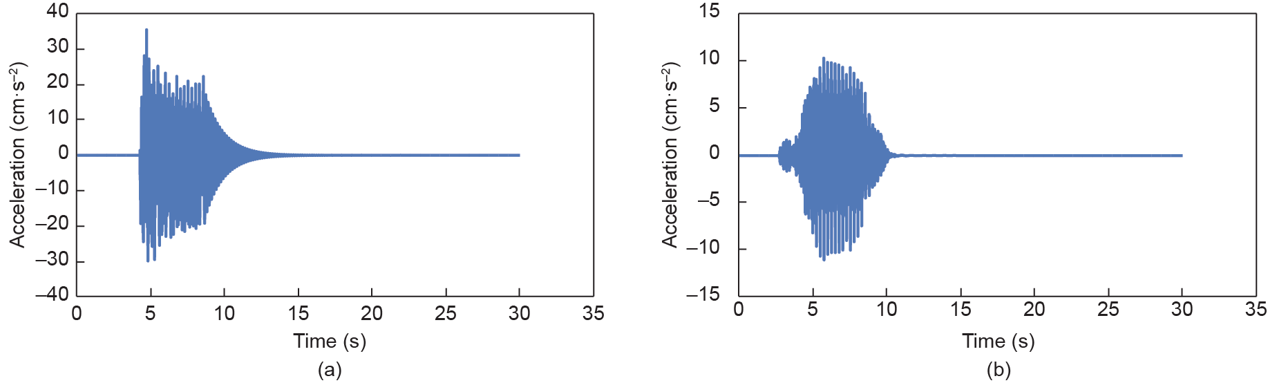
Fig. 10. Accelerations at the middle of the 6th span. (a) Vertical history; (b) lateral history.
《Fig. 11》
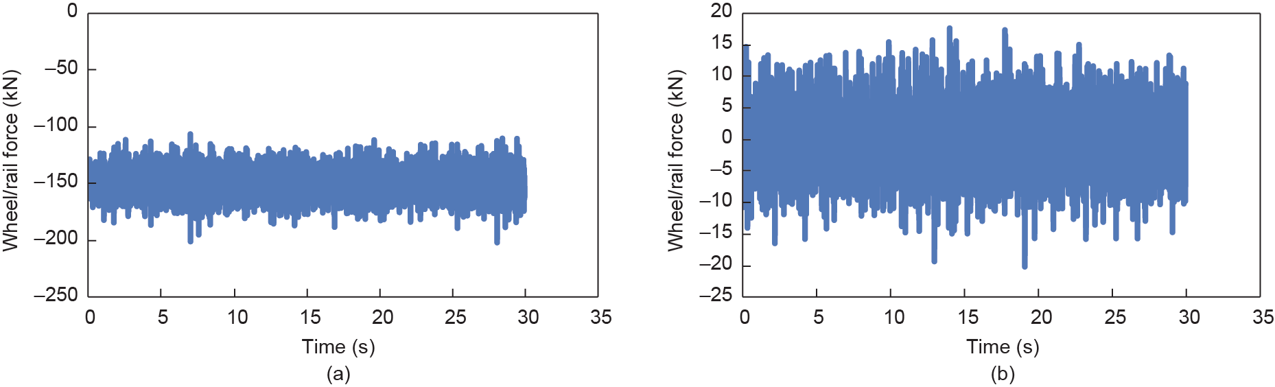
Fig. 11. Wheel/rail forces of the 1st wheel set. (a) Vertical history; (b) lateral history.
《Fig. 12》

Fig. 12. Accelerations of the 1st car body. (a) Vertical history; (b) lateral history.
Figs. 13–16 show the factors mentioned above versus train speed within the range of 200 km·h–1 to 400 km·h–1; the solid line stands for the maximum wheel/rail force and the dashed line represents the minimum wheel/rail force in Fig. 15.
As can be seen in Figs. 13–16, the vertical and lateral wheel/rail forces (Fig. 15) maintain a constant growth with the increase of train speed, while other dynamic factors of the bridge and the train present different variation trends. Within the concerned train speed range, the peak lateral car body acceleration is found under 275 km·h–1 (Fig.16(b)) and the peak lateral bridge acceleration is found under 300 km·h–1 (Fig.14(b)), which implies there is some possibility of lateral resonance of the train-vehicle dynamic interaction system. But no obvious peak is found in the vertical responses, including the bridge vertical displacement, the bridge vertical acceleration, and the car body vertical acceleration. It can be concluded that there is no resonant vibration in vertical direction for the concerned cases.
《Fig. 13》
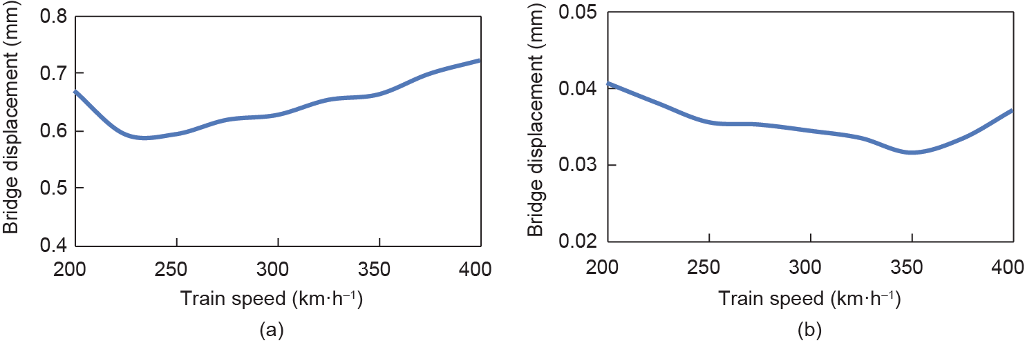
Fig. 13. Bridge displacement versus train speed. (a) Vertical displacement; (b) lateral displacement.
《Fig. 14》
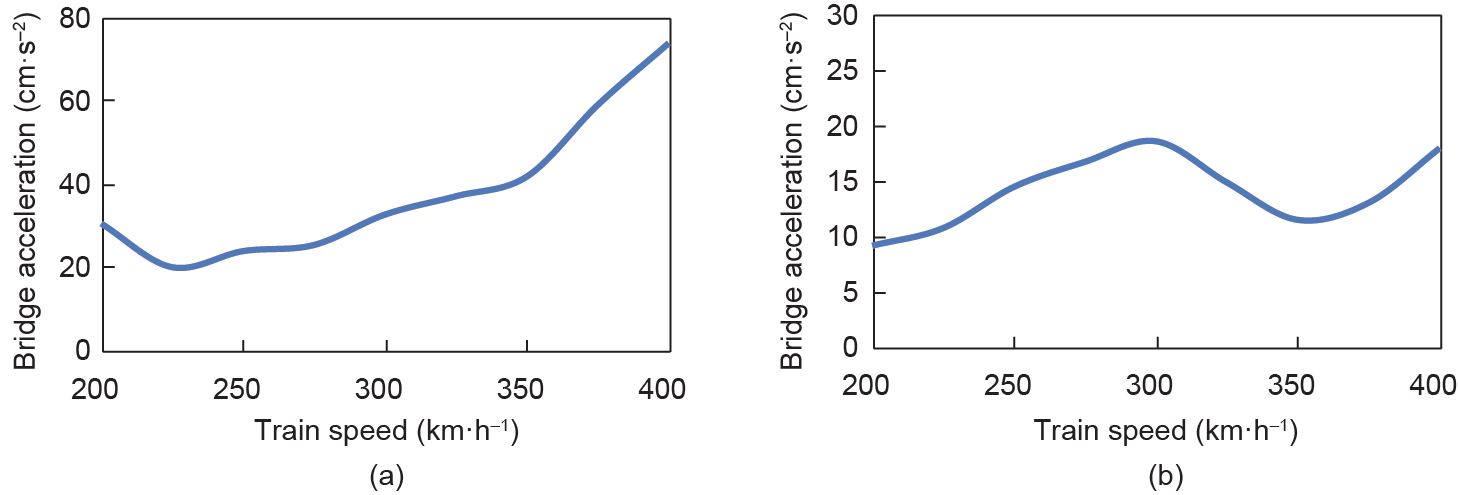
Fig. 14. Bridge acceleration versus train speed. (a) Vertical acceleration; (b) lateral acceleration.
《Fig. 15》
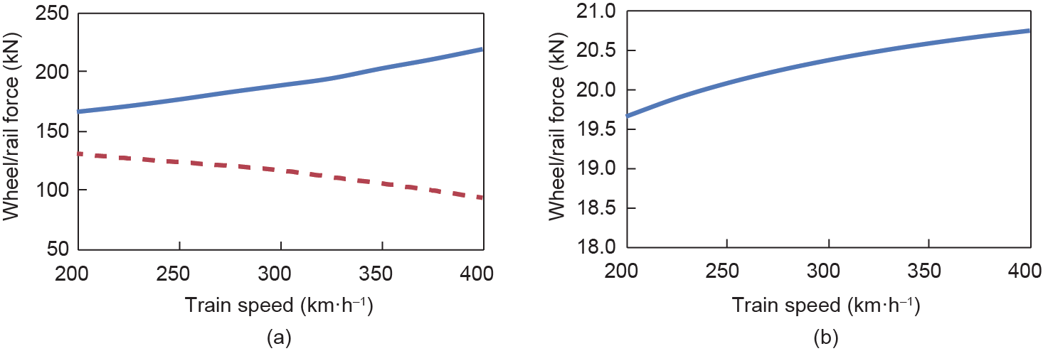
Fig. 15. Wheel/rail force versus train speed. (a) Vertical force; (b) lateral force.
《Fig. 16》
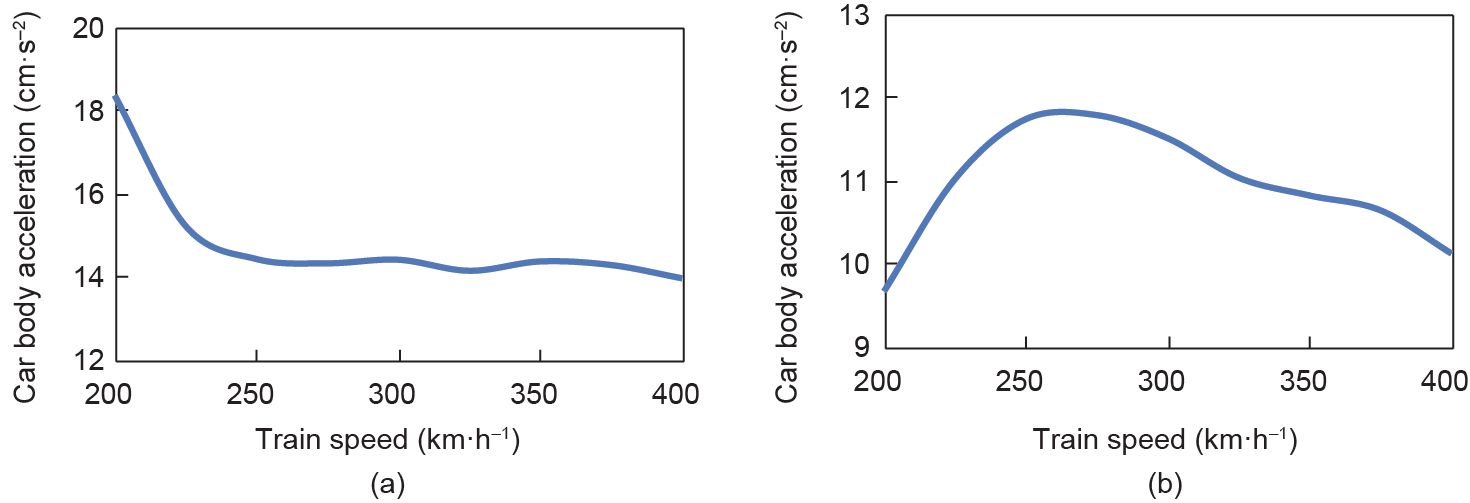
Fig. 16. Car body acceleration versus train speed. (a) Vertical acceleration; (b) lateral acceleration.
《4. Summary》
4. Summary
A dynamic analysis model for the train-bridge interaction system is established and its solving method is proposed: The train vehicle is modeled by the rigid-body dynamics method, the bridge subsystem is modeled by the finite element method, and the wheel/rail vertical and lateral interactions are simulated by the corresponding assumption and by the Kalker linear creep theory, respectively. The train-bridge interaction system is solved by inter-history iteration. The case study focuses on the dynamic response of a CRH380BL train running through a standarddesign bridge in the Chinese high-speed railway system. It is found that the vertical and lateral wheel/rail forces increase with the train speed, while the maximum vehicle and bridge responses change in a complex relation due to the resonance between the vehicle and the bridge subsystems. There is some possibility of lateral resonance of the train-vehicle dynamic interaction system between 275 km·h–1 and 300 km·h–1, while no resonant vibration in vertical direction for the concerned cases.
《Acknowledgements》
Acknowledgements
This research is sponsored by the Major State Basic Research Development Program of China (“973” Program) (2013CB036203), the 111 Project (B13002), and the National Natural Science Foundation of China (U1434205, U1434210, 51338001).
《Compliance with ethics guidelines》
Compliance with ethics guidelines
Nan Zhang, Yuan Tian, and He Xia declare that they have no conflict of interest or financial conflicts to disclose.


 京公网安备 11010502051620号


