

《1. Introduction》
1. Introduction
Cell rotation is a cell manipulation technique that enables three-dimensional (3D) cell imaging [1-4] and observation from a specific angle [5,6]. The rotational motion [7,8] of cells under certain conditions (e.g., electrorotation) is an important label-free biomarker for cell discrimination. The approaches used for cell rotation can be divided into six groups according to the applied mechanisms: optical field [9,10], mechanical contact [11], magnetic field [12,13], electric field [14,15], acoustic field [16,17], and hydrodynamic field [18,19] methods, as illustrated in Fig. 1(a).
《Fig. 1》
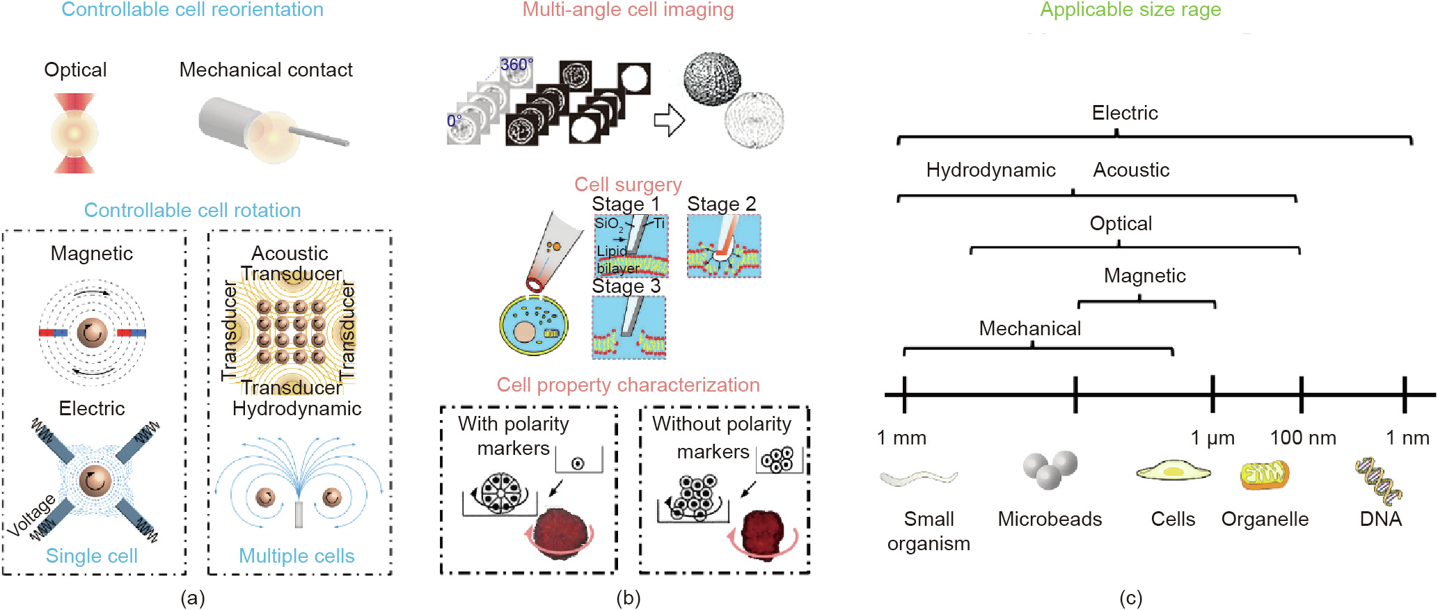
Fig. 1. A schematic overview of the six groups of approaches used for the rotational manipulation of cells. (a) Cell rotation methods with different external forces, i.e., the optical field- and mechanical contact-based approaches, are commonly applied for cell reorientation, while the other four types of field-based techniques (magnetic, electric, acoustic, and hydrodynamic) are mainly used for cell rotation at a steady speed. (b) Applications of cell rotation and orientation include multi-angle cell imaging [34], cell surgery [35], and cell property characterization [33]. (c) The applicable size range differs for each approach group and ranges from 100 to 1 mm. Reproduced from Ref. [34] with permission of Springer Science Business Media, LLC, part of Springer Nature, ©2020; Ref. [35] with permission of American Chemical Society, ©2011; and Ref. [33] with permission of National Academy of Sciences, ©2012.
Cell populations are heterogeneous, and even cells of the same type differ from each other, since living biological cells vary in their shapes, sizes, and other biophysical features [20]. It is of great importance to detect and visualize the biological dynamics of cell surface morphologies in biological, medical, and clinical applications [21]. However, confocal microscopy, a commonly used optical technique for cell image acquisition, is limited to transparent samples and certain visible angles, and has limited resolution in the XY plane (100 nm) and Z direction (200 nm). In comparison with other available setups, such as 3D structured illumination microscopy (SIM) [22-24], on-chip cell rotation under a confocal microscope is a more affordable way to enhance spatial resolution and achieve 3D visualization of cell dynamics, due to its low reagent consumption, fast sample processing, high integration, portability, and low cost. For example, on-chip cell rotation activated by acoustic tweezers [25] has been applied to build highresolution 3D optical reconstructions under an ordinary confocal microscope with a visible angle of up to 140° [1]. Furthermore, the integration of optical tweezers (OTs) [26,27] in microfluidic devices further extends the visible angle of cells to 180° and enables the visualization of cells from a specific angle in a process known as cell reorientation. Due to its capability to reorientate and visualize cells, optical-activated on-chip cell rotation has enabled a wide range of applications in cell surgery processes (e.g., cell injection, intracellular structure biopsy, and organelles extraction), in which target cells are required to be properly orientated in order to mitigate side effects on cell viability [28,29]. For example, in mammalian oocyte manipulation, the polar body of the oocyte must be rotated away from the injection site to prevent damage to the spindle, which is close to the polar body inside the oocyte [3,30]. Other examples include the necessary, precise control of cell orientation in order to avoid damage to organelles in the cell and thus increase the success rate of micromanipulation [31,32].
The rotational motions of cells of different shapes or types vary even under the same conditions, so cell rotation can be used to characterize cellular properties and status in relation to the chemical composition or physical features. In a breast cancer study [33], the rotational motion of cancer cells was found to be distinguishable from that of normal cells having spherical shapes. A stable rotation, or so-called coherent angular motion, was necessary for normal cells to form spheres. However, the study pointed out that the loss of polarity prevented cancer cells from forming spheres, which is one of the earliest signs of malignancy and which leads to rotational motion disorders, as shown in Fig. 1(b) [33-35]. In addition, the physical features and chemical composition of cells (e.g., the dielectric properties of cells) are accessible from cellular rotational motion based on lab-on-a-chip techniques. For example, Han et al. [15] proposed a microfluidic device with a nonuniform electrical field, which was applied to analyze the rotating patterns of target cells (e.g., rotation speed and direction), and Huang et al. [36] demonstrated its capability for cell characterization and discrimination. The controllable rotation of cells and microbeads is a tool that allows researchers to uncover the mechanical properties of target components. For example, the rotation of magnetic beads under a rotating magnetic field enables the high-speed measurement of the structural dynamics of DNA gyros [37,38]. Similarly, acoustic-field-based rotation is preferred for cell characterization due to its capability to excite the rotation of numerous particles with a relatively large output force [39]. Rotation strategies based on external acoustic fields also enable the parallel analysis of multiple bio-samples [40,41] with either open or closed microfluidic devices, although the stability of multi-cell control needs further improvement.
Although there are several on-chip methods for cell rotation, each method has a limited applicable range of cell sizes, as summarized in Fig. 1(c). For small organisms or microbeads, three types of manipulations (mechanical, acoustic, and hydrodynamic) are available, with applicable sizes of up to 1 μm. Optical field approaches are suitable to rotate cells or organelles varying in size from 0.1 to 100 μm, due to the low output force. Magnetic field approaches are primarily used to rotate magnetic beads with sizes ranging from 1 to 10 μm. Lastly, electric field approaches can be used to rotate samples with various sizes ranging from 0.001 to 1000 μm. Noticeably, although both optical and mechanical approaches have relatively higher spatial resolution (up to 0. 1 nm) than other approaches (resolutions are summarized later in Section 4), which contributes to the precise control of rotation angle, both have limitations in real applications. Mechanical contact approaches carry a high risk of injuring soft cell membranes and impairing cell viability, while OTs with high optical intensities (normally > 105 W·cm-2 ) show a tendency to kill cells or cause optical damage, limiting their applications.
This review aims to analyze representative academic studies utilizing six major groups of approaches to rotation (either direct contact or non-contact approaches, as shown in Fig. 1(a)). We then provide additional details about the merits and demerits of each approach under different conditions and discuss possible future trends in this field. We have classified the approaches in these six groups into two classes based on the purpose of rotation: cell reorientation and cell rotation (Fig. 1(a)). More specifically, controllable cell reorientation aims to rotate cells precisely toward a specific angle, and is mainly performed using an optical field or mechanical contact. In contrast, controllable cell rotation aims to rotate the cell at a steady speed; in this case, a magnetic field or an electric field is commonly used to rotate single cells, while acoustic field or hydrodynamic field approaches mainly focus on the rotation of multiple cells in parallel.
《2. Controllable cell reorientation》
2. Controllable cell reorientation
Precise cell orientation is necessary for cell microinjection, for the precise delivery of substances into cells, and for the study of cell transfection, signaling pathways, and organelle functions [42- 45]. To enable injections at specific locations of an embryo and to avoid any damage to specific internal organelles, it used to be necessary to manually adjust the position and posture of the cells, which was limited by low efficiency and a low success rate [31]. Currently, automated processes are gradually replacing the existing manual reorientation strategies. For example, a closed-loop control manipulator driven by a direct current (DC) motor [5,46] can provide repeatable and fast positioning of cells with a spatial resolution greater than 0.1 μm, which is difficult to achieve by manual operation.
《2.1. Mechanical contact approaches》
2.1. Mechanical contact approaches
Mechanical contact approaches utilize tools (e.g., micropipettes with certain fabrication specifications) mounted on a manipulator that directly interact with the target cell to achieve the translocation or reorientation of cells. Compared with manual reorientation approaches that require highly skilled operators, the use of manipulator and control systems enables mechanical contact approaches to simplify operation processes and reduce cell damage [4,5,47].
The great majority of mechanical contact approaches aim to replace operators with micro-robotics (Table 1 [4,46-52]). For example, Wang et al. [46] proposed a method for the real-time recognition and reorientation of embryos, in which the reorientation of target cells is powered by frictional force related to cellular deformation (Fig. 2(a)), with 2° of rotational freedom and a success rate of up to 97.50%. Furthermore, as shown in Fig. 2(b), a push force controlled by programs [48] can orientate cells with a rotation angle error of 5°, although the degree of freedom (DOF) of this approach is limited to one. Alternatively, as shown in Fig. 2(c)), multiple micropipettes can function as fingers [4], where the target cell is held by one ‘‘finger” and rotated by another one, which reduces the rotation error to around 1.2°. Based on the minimum rotational force model, a varying torque is applied to rotate target cells according to the cellular deformation, which successfully minimizes the side effects on cell viability, albeit with some cost to manipulation efficiency. Recently, an improved method [49] has been developed that optimizes the direction of the injection micropipette and significantly reduces the processing time to 5 s·cell-1 . Meanwhile, with two micropipettes, the system [50] can achieve a success rate as high as 92.5% with a maximum error of 0.3°.
《Table 1》
Table 1 Summary of publications describing the development of cell reorientation using mechanical contact approaches.

DOF: degree of freedom.
《Fig. 2》

Fig. 2. Schematic representations of different mechanical contact methods. (a) friction-based technique using friction force to drive the rotation of target cells; (b) push-based technique using push force to rotate target cells on the substrate; (c) Grapple-based technique using micropipettes as robotic fingers to rotate target cells. R: radius; θ: angle.
At present, mechanical contact-based methods are widely used for cell reorientation, although they carry the risk of physical damage and undesired stimulation [55]. These methods allow a relatively high spatial resolution (up to 0.01 μm) for particle reorientation and manipulation, ensuring the repeatability of similar orientational manipulations. Moreover, a rotation accuracy of 0.3° has been achieved with mechanical contact-based techniques, which is much smaller than that of other manual methods (8.3°) [4]. Although many improvements of the control system have been made to enhance the stability and precision of the operation, the minimum applicable size is limited to about 100 μm.
Compared with the direct rotation of cells, rotational control by means of microfluidic devices is much simpler and more accessible for cell observation. Aishan et al. [52] established an observation platform by fabricating an all-closed glass chamber through combining the techniques of thermal-expansion-based glass-domestructure fabrication [53] with ultra-thin glass fusion bonding [54], in which high-precision control of the observation angle was achieved with an error of 0.72°. The target cell was placed in a closed chamber to reduce the risk of outer contamination during observation and to eliminate possible physical damage caused by stiff actuators; however, an all-closed microenvironment limits other applications such as cell surgery.
《2.2. Optical field approaches》
2.2. Optical field approaches
OTs have become one of the most popular optical-field-based techniques applied in cell rotation, after first being investigated by Ashkin et al. [56,57]. A highly focused laser beam functions as an optical trap that applies trapping force and torque to particles of interest, allowing the label-free manipulation of captured micron-sized dielectric particles [58-62]. In contrast to mechanical contact approaches, the stiffness and magnitude of the forces applied by OTs vary with the intensity of the laser beams, and the trapping forces of OTs vary in a range from femto-newtons to nano-newtons, which makes them well-suited for capturing micron-sized particles with different sizes and weights [63,64]. Furthermore, dual-beam optical traps have shown the capability of cell reorientation [65,66], and their self-organizing property [67,68] has been verified using counter-propagating laser beams. The selection of appropriate laser beams for the manipulation of red blood cells and cancer cells was described in the study by Kreysing et al. [69] and Dasgupta et al. [70]. In addition, in the past research [71,72] of our team, we found that a focused femtosecond laser beam can induce impulsive forces without any thermal effects, enabling non-contact cell manipulation. Although few studies have been published on cell rotation by OTs, this topic may become a research trend.
2.2.1. Optical trapping forces and cell refraction
Optical trapping forces, which are generated as a result of the interaction between a focused laser and the trapped object, enable the rotation of target cells via OTs under an ordinary commercial microscope. A typical apparatus (Fig. 3(a)) used for optical manipulation mainly consists of some optics components, such as a microscope with a bright field or illumination, a high numerical aperture (NA) objective lens, and a condenser detection lens. Typically, the wavelength of the applied laser beam is near-infrared, which avoids various kinds of biological photo-damage and can easily be incorporated with other visible light forms [73] in the imaging system. Furthermore, a trapping laser can be coupled with a single-mode optical fiber to produce a clean beam profile, and can then be split by a spatial light modulator (SLM) into multiple simultaneous trapping beams. Therefore, the manipulation of multiple cells can be performed in parallel utilizing holographic OTs.
Fig. 3(b) illustrates the changes in the propagation path of laser beams before and after entering the cell, and shows the momentum transformation that occurs at the cellular surface. Based on Snell’s law, the refraction alters the propagation direction of two incoming laser beams, ki,1 and ki,2. The momentum relation between the incoming and outgoing beams, ks,1 and ks,2, can be formulated as follows.

Following momentum conservation, the momentum of both laser beams,  and
and  , and is transferred onto the target cell. As a result, trapped particles experience a compensatory momentum
  , pointed toward the focal point, as shown in Fig. 3(b). Due to the effect of scattering force, OTs are capable of capturing dielectric microparticles through a highly focused laser beam and trapping them at a point behind the focal plane (Fig. 3(b)).
《Fig. 3》

Fig. 3. Overview of an optical technique for cell rotation and manipulation. (a) Illustration of the apparatus used for the optical rotation of biological cells. (b) Laser light momentum transfer for the target cell, wherein: I: the target cell is placed in the upper right of the focal plane; and II: the target cell is placed in the bottom right of the focal plane. (c) Schematic representations of different optical rotation strategies: I–III: OTs are directly used to manipulate cells; IV–VI: indirect optical rotation methods. F: force; R: radius.
2.2.2. Optical tweezers for cell reorientation
Fig. 3(c-I–III) shows schemes for the direct optical rotation of cells, a method that has attracted great attention due to its high precision [9,67]. Xie et al. [74] recently reviewed the rapid development of robot-aided OT systems over the past decades, which illustrates the operation of multiple laser beams for cell rotation. Aided by a closed-loop system, Xie et al. [5,75] also realized the rotation control of target cells in either the XY plane or the YZ plane, by controlling both laser tweezers' trajectories or distance (Fig. 3(c-II–III)). The robot-aided approach is fairly reliable and is applicable for more demanding tasks, such as the spin and orbital rotation of cells. In a study by Chen et al. [65], two OTs with 10 μm displacement could rotate red blood cells at an approximate speed of 72.2°·s-1 ; however, when the displacement increased to 15 μm, the cells were found to move along an elliptical orbit (150.7°·s-1 ) while self-rotating at 57.3°·s-1 .
One limitation of OTs is the optical damage that they cause. A study pointed out that a relatively high optical peak intensity (>105 W·cm-2 ) [76] is necessary to generate stable traps; however, as shown in Table 2 [5,65,75,77-80], such highly intensive laser irradiation [81] may result in photo-damage to cells or tissues [82]. More specifically, direct laser irradiation may lead to various side effects at the single-cell level, such as local overheating [83], changes in cell metabolism [84], molecular photo-conformation [81,85], protein denaturation [86], and photomechanical stress [87], all of which eventually cause the loss of cell viability. Thus, despite the fact that OTs provide very precise rotation control, photo-damage must be taken into consideration. Other adverse impacts of direct laser exposure include Brownian motion and thermal disturbance [88], which can further disturb the trapped particles.
Alternatively, indirect optical rotation can avoid these side effects of direct laser exposure and mitigate photo-damage. Table 2 summarizes the photo-damage occurrence rate for each optical rotation approach. As shown in Fig. 3(c-IV–VI), these approaches can be divided into three categories: topological grippers, pushing-based methods, and attached particles. For example, topological grippers [5,78,80] are formed by several beads (Fig. 3(c-IV)) and controlled by multiple laser beams; they can reduce the laser exposure on cells by 90%. Some cells are still sensitive to the remaining 10% laser exposure, and their physiological characteristics will change during topological gripper use. This issue has been dealt with by placing an intermediate bead between the target cell and the optically manipulated beads [77,79], as shown in Fig. 3(cV–VI), where the optically trapped beads act as a non-contact actuator and eliminate almost all side laser effects on the target cells.
《Table 2》
Table 2 Summary of publications describing the development of cell rotation using optical field approaches.

Another limitation of OT rotation is the lack of selectivity and exclusivity. In other words, OTs will trap any dielectric particle near the laser focal point [89]. Relatively low concentrations of cells, therefore, are required in order to prevent the collision and capture of additional particles. Significant efforts [90-92] have been made to attenuate the influence of high concentration on cell manipulation, such as through trajectory planning algorithms to optimize cell manipulation. In addition, the applications of optical-based rotation techniques are limited by the low output forces of OTs. For example, single-beam optical rotation can generate a trapping force that is only sufficient to rotate a cell of about 10 μm, and is insufficient to rotate larger ones such as oocytes (>100 μm) [93].
In this section, we reviewed two rotation techniques—optical rotation and robot-aided mechanical rotation—for cellular reorientation with precise angle control (not at the rotation speed). Controllable cell rotation is necessary for some other cases, such as analysis of the rotational characteristics of cells and 3D optical reconstructions; this topic is reviewed below.
《3. Controllable cell rotation》
3. Controllable cell rotation
Herein, ‘‘cell rotation” refers to the rotation of target cells at a steady and controllable rate. Precise single-cell rotation is important for many applications in biotechnology, such as cell characterization [94], drug discovery [95,96], tumor heterogeneity profiling [97,98], and cell imaging [1,10]. In this section, cell rotation is actuated by non-contact physical fields, such as electric, magnetic, acoustic, and hydrodynamic fields (Fig. 1(a)).
《3.1. Electric field approaches》
3.1. Electric field approaches
Cells can rotate in a rotating electric field in which the rotational torque is generated by the phase difference between the dipole moment of the cell and the rotating electric field. Furthermore, in a non-rotating electric field, rotational motion can be stimulated by an uneven or time-varying electric field. In an alternating current (AC) field, the electric torque, which is induced by dielectrophoresis (DEP), is able to manipulate particles ranging from a few nanometers to hundreds of microns in size by altering the field strength, frequency, or electrode geometries. DEP [99- 101] has many unique features, including low cost, high efficiency, and a low injury rate. In addition, different particles may respond differently to an electric field. For example, the rotation direction of Janus particles is related to the AC frequency [102], which causes the particles to co-field rotate at a low AC frequency and vice versa. Meanwhile, DEP is capable of distinguishing and separating different types of cells based on the motion of the cells, which is related to the cells’ dielectric properties.
3.1.1. Dielectrophoresis and electrorotation
The fundamentals of DEP forces have been well described in the literatures [99-101,103]. Theoretically, a cell can be polarized in a nonuniform electric field [104]. If it is more polarized than the medium, a net force toward the strong electric field is generated, known as positive DEP, and vice versa. Based on this theory, Chow et al. [105,106] designed a liquid metal-filled multifunctional micropipette and achieved four-dimensional (4D) single-cell rotation (Fig. 4(a) [106]) by forming an unbalanced force torque at different positions on the cell surface.
《Fig. 4》

Fig. 4. Controllable cell rotation strategies based on the electrical field. (a) Schematic of 4D electrorotation near the pipette tip; (b) illustration of the microdevice for 3D cell electrorotation and the working principles of single-cell loading and 3D rotation; (c) illustration of electric field lines on coplanar electrodes and the rotation strategy; (d) distribution of multiple electrodes; (e) operation scheme for the electrodes and cell trapping on the insulating layer for rotational manipulation.  : phase of AC signal; +φ: positive electrode; –φ: negative electrode; FnDEP: negative DEP force; FpDEP: positive DEP force; Fdrag: viscous drag force; E1/E2: the decrease direction of electrical potential; ω: frequency of AC signal; t : time; frequency of AC signal; PDMS: polydimethylsiloxane; ITO: indium tin oxide. Adapted from Ref. [106] with permission of WILE-VCH Verlag GmbH & Co. KGaA, ©2018; Ref. [7] with permission of Royal Society of Chemistry, ©2018; Ref. [112] with permission of SAGE Publications Ltd, ©2015; and Ref. [113] with permission of WILE-VCH Verlag GmbH & Co. KGaA, ©2018.
A homogeneous spherical cell with radius R in a uniform electric field E is equivalent to a dipole with a moment phasor (Fig. 4 (b) [7]). In a DEP biochip [107], the dipole will interact with the external electric field and generate a DEP force, as expressed below:

where the DEP force (FDEP) is proportional to the real part of the complex Clausius–Monssotti factor  , and
, and  and
and  are the medium permittivity and particle permittivity, respectively. The * represents the complex variable, and the complex permittivity,
  , is linearly associated with the substance permittivity (
 ) and angular frequency (
 ) of the rotating field. Additionally, Re(∙) stands for the real part of a complex variable,
  is the medium conductivity, and i is the imaginary unit.
In a rotating electric field, cell rotation can be derived by the electrorotation torque (ROT).

where the ROT is proportional to the imaginary part of the complex Clausius-Monssotti factor, zis a unit vector normal to the surface of the electrode, and Im(∙) stands for the imaginary part of a complex variable. The phase delay between the electric dipole and the external field results in a relative lag angle between the two rotational torques. In a steady-state equilibrium condition, the rotation speed or angular velocity [15] can be defined as follows:

where the rotation speed  is proportional to the imaginary part of the complex Clausius-Mossotti factor, and
  is a scale factor [108,109] (typically a constant) related to the viscosity () and the electric field strength.
3.1.2. Electric field for cell rotation
Walid and Dutta [110] realized cell rotation in a stationary electric field by an AC signal with time-varying frequency, in which a nonuniform electric field was generated to polarize the target cells (Fig. 4(c)). They found that the rotation speed in a stationary electric field is tightly associated with the AC frequency, although the underlying mechanism is not fully understood. Furthermore, the steady rotation of a cell is not only related to its regular shape, but also influenced by eccentric inclusions with low conductivity inside the cell [111]. Currently, the use of a stationary electric field for cell rotation is still limited by the low precision of the speed control.
Alternatively, Han et al. [15] designed a ROT-based microchip to trap and rotate cells with an electric signal (Table 3 [7,15,102,105,106,110-114]), in which the speed and direction of cell rotation was a sensitive function of the cell’s dielectric properties [36] (e.g., the conductivity and dielectric constant). Four electrodes were used to form a time-changing electric field required for cell rotation, and each electrode was energized by AC signals with different phase delays. It was also suggested [112] that there should be no more than four electrodes in real applications. Although the area of the rotating field expands as the number of electrodes increases (Fig. 4(d) [112]), the intensity of the central field remains the same and the control of multiple electrical signals becomes much more complex [115]. The only benefit of multiple electrodes is to minimize the effects of electric field distribution on cell rotation, as the uniformity of the electric field is improved.
《Table 3》
Table 3 Summary of publications describing the development of cell rotation using electric field approaches.

nQDEP: negative quadrupolar dielectrophoretic force.
In addition, it is recommended that cells not be rotated in the central electric field, as this may disrupt the electric field and could even terminate an experiment. To stabilize the rotational motion, Huang et al. [114] reported a new design of the DEP platform, which has the ability to trap single cells and achieve 3D rotation at the same time. By adjusting the AC signal configurations, cells can be rotated steadily, and the control process is much simplified. To further simplify such microdevices and extend the scope of applications, Huang et al. [7] presented a new electrorotation-ona-chip technique (Fig. 4(b)). This method has advantages in performing 3D rotation in terms of controllable direction, speed, and axis of rotation on a single microchip with a typical structure, such as the structure described above. Based on the same design, Huang et al. [116] realized self-adaptive spatial localization control and the 3D morphology reconstruction of single cells. Compared with the multi-electrode design, Huang et al. [113] and Feng et al. [117] found that polarized cells can also work as electrodes; this novel electrorotation mechanism greatly simplified the design of DEP-based microchips (Fig. 4(e) [113]). Chow et al. [105,106] fabricated a liquid metal-filled multifunctional micropipette for rotating cells in liquids (Fig. 4(a)); the micropipette can simultaneously generate a 3D DEP trap and a one-dimensional (1D) ROT. One unique advantage of this approach is that no microfabrication or lithography steps are required in order to form electrodes, which simplifies the fabrication process and reduces the fabrication cost.
In general, we can conclude that the applicable size range of electric field approaches (i.e., 0.001–1000 μm) is much wider than that of other approaches (see Section 4 later for a summary of the ranges). To date, most research has focused on cell rotation with only one DOF, rather than on cell rotation along multiple axes, which is still a challenge (Table 3); only Huang et al. [7] have successfully achieved cell rotation with three DOFs in an electric field with the aid of four electrodes.
《3.2. Magnetic field approaches》
3.2. Magnetic field approaches
Magnetic-field-based tweezers [118-120] are a reliable tool for studying the mechanical properties of biological micro-molecules, such as nucleic acids and proteins comprising single molecules. A magnetic object placed in the magnetic field will experience a magnetic force and/or a magnetic torque, on the order of pico- to nano-newtons. Unlike electric tweezers, which are prone to cause undesired electrochemical reactions [121] and impair cell viability, the magnetic field has virtually no influence on biological samples. One of the limitations of this approach, however, is that biomolecules or cells of interest must be attached to magnetic particles for transportation, separation, and detection [122-125]. Fig. 5(a) [13] shows an example of a T cell attached to a magnetic Janus particle and rotated by an external magnetic field [13]. Given that the target cells require pretreatment, some research studies have shown that physiological characteristics may be changed as a result of attached magnetic beads [126,127]. Another problem is that it is difficult to release the attached beads after the measurements of cell mechanical properties.
Magnetic tweezers (Fig. 5(b) [89]) are formed when an external magnetic torque [89] is applied to magnetic microparticles. This technique is often used with OTs to trap target particles in specific places, as well as to overcome the limitations of OTs (i.e., photodamage and thermal effects) on bio-sample manipulation. For example, Ye and Sitti [88] proposed the integration of both techniques to create a local vortex to transport nearby microorganisms along a circular path. However, Romodina et al. [122] reported that laser-induced local overheating will break down synchronous states between rotating particles and rotating magnetic fields, as the rotational motion will be delayed by the heat-related Brownian torque. In additional to optical trapping, fluidic trapping can be used in this case, and has been realized based on nickel nanowires [128,129] (Fig. 5(c) [128]) and a dumbbell-shaped magnetic actuator (Fig. 5(d) [130]). Both approaches have the ability to generate mobile micro-vortexes under a rotating magnetic field, in which cells can be trapped and rotated at a speed of up to 399.92°·s-1 and 324.87°·s-1 , respectively.
《Fig. 5》

Fig. 5. Controllable cell rotation strategies based on magnetic tweezers. (a) Rotation control of T cells using magnetic Janus particles; (b) schematics showing the insert, which holds two electromagnets on a microscope stage; (c) tangential flow field and cell rotation activated by the rotation of a nanowire; (d) dumbbell fluidic tweezers for the dynamic trapping and rotation of cells; (e) experimental results and schematics showing the layout of magnetic tweezers based on permanent magnets. CD3: cluster of differentiation 3; V : translation speed; M1, M2, M3, M4: electromagnet. Adapted from Ref. [89] with permission of Springer Nature, ©2008; Ref. [128] with permission of American Chemical Society, ©2011; Ref. [130] with permission of WILEY-VCH Verlag GmbH & Co. KGaA, ©2016; Ref. [13] with permission of WILEY-VCH Verlag GmbH & Co. KGaA, ©2016; and Ref. [134] with permission of Springer Nature, ©2018.
Theoretically, in the magnetic field, ROT exerted on the magnetic dipole is defined as ROT = m × B, where m is the magnetic dipole moment of the particle and B is the external magnetic field. Under the influence of a magnetic torque, a magnetic particle will rotate until the direction of the dipole is aligned with the magnetic field. Thus, a time-variant magnetic field can cause a magnetic particle to rotate on a three-dimensional (2D) surface at a stable velocity. Thus far, numerous research studies have been done to measure the torque [131,132] or forces [120] exerted on cells, DNA, and so forth under a time-variant magnetic field. However, as previously described, the Brownian motion may destroy the synchronization states, and the torque applied by the magnetic tweezers is not constant due to the difference in magnetization between magnetic beads [133], which makes it difficult to precisely quantify the magnetic force.
Similar to DEP-based rotation, most magnetic-based studies have realized a single degree of rotational freedom, rather than 3D control. In a study by Berndt et al. [134], the magnetic field was found to be capable of controlling the rotation of living specimens in a 3D space without any magnetic beads attached (Fig. 5 (e)). However, this approach carries the risk of impairing the testing samples because of the excessive magnetic force applied for manipulation. In contrast, dumbbell fluidic tweezers (Fig. 5(c)) are a much safer way to achieve cell rotation, and a relatively fast rotation is achieved by non-contact manipulation (i.e., a mobile micro-vortex). However, the rotation speed of individual cells is unstable and varies with time. To date, precise cell manipulation for rotation or reorientation is still a daunting task for magnetic tweezers; thus, their use is still not recommended for both cases, except for larger model organisms that are commonly used in developmental biology, and which require high driving torques for actuation.
《3.3. Acoustic field approaches》
3.3. Acoustic field approaches
Acoustic-field-based tweezers can control objects in real time through the interactions of sound waves with solids, liquids, and gases, as first proposed by Wu [135] to capture and linearly translocate 270 μm latex particles and frog eggs. This technique can be applied for the manipulation of multiple bioparticles across a wide size range (0.1–1000 μm). The applications of acoustic tweezers can be roughly divided into three categories according to the working principles: ① standing-wave tweezers, ② traveling-wave tweezers, and ③ acoustic streaming tweezers. Among these, the first two groups are direct manipulation strategies with external acoustic radiation forces, while the last one is an indirect manipulation strategy induced by fluid flow.
3.3.1. Standing-wave tweezers
A standing wave is characterized by the ability to form a stable distribution of an acoustic potential energy field and a mechanical field. According to the generation method of an acoustic wave, standing waves can be further divided into two subtypes: surface acoustic waves (SAWs) and bulk acoustic waves (BAWs).
SAWs, which propagate along the surface of an elastic material, are typically generated on interdigital transducers (IDTs). Such transducers can convert electric signals to SAWs and generate periodically distributed mechanical forces. SAWs can move particles, cells, or microbes as precisely as OTs, and the particles in the acoustic field are pushed to either acoustic pressure nodes (i.e., minimum pressure regions) or pressure antinodes (i.e., maximum pressure regions), depending on the density and compressibility of the particles (Fig. 6(a) [136]). Moreover, this technique can manipulate particles independently of shape and can manipulate many particles in parallel; both types of manipulations are impossible for OTs [39]. Additionally, SAWs have potential for particle alignment. Bernard et al. [137] reported that non-spherical particles are prone to rotate and align with anisotropic potential wells. Furthermore, the applicable environment of SAWs is not limited to sticky conditions, such as in a droplet; for example, Yu et al. [138] reported that a SAW field with an annular-type pattern can be formed. In such droplets, as the distribution of the acoustic potential changes according to the acoustic amplitude, the internal particles exhibit different dynamic behaviors, such as rotation and translocation. Guo et al. [139] took advantage of this phenomenon to achieve the aggregation of a large number of beads, form specific shapes, and reorient the aggregated beads toward a signal input.
Compared with OTs and electric tweezers, which are typically used to manipulate single cells, acoustic tweezers are capable of rotating a large number of cells in parallel. Additionally, acoustic tweezers (e.g., 150 pN on particles smaller than 5 μm) have a larger output force on particles of the same size compared with magnetic tweezers (50 pN) or OTs (10 pN) [39]. It is worth noting that the applied wavelength of the acoustic waves must be comparable to the size of the particle in order to stably manipulate submicron particles.
BAWs are generated on a piezoelectric transducer and are typically used inside a microchannel. As shown in Fig. 6(b) [136], the reflected wave on the reflector interacts with the original wave, which produces pressure nodes and antinodes in the channel for multi-cell manipulation. Also, the number of these nodes can be changed by adjusting the voltage frequency relative to the geometric dimensions of the channel [140]. At present, this technique is commonly used for cell separation or focusing, and is rarely used for cell translation and rotation.
《Fig. 6》

Fig. 6. Illustration of various acoustic-tweezer technologies. (a) SAW-based standing-wave tweezers; (b) BAW-based standing-wave tweezer device; (c) active travelingwave tweezers; (d) passive traveling-wave tweezers; (e) acoustic streaming tweezers; (f) solid-structure-based acoustic streaming tweezers. Adapted from Ref. [136] with permission of Nature Methods, ©2018.
3.3.2. Traveling wave tweezers
As shown in Figs. 6(c) and (d) [136], traveling wave tweezers are mainly used for acoustic levitation. According to a review by Ozcelik et al. [136], they can be roughly divided into two groups, depending on the applied generator: namely, active methods and passive methods. The key difference is the number of transducers used; for the former, a relative phase delay between sound waves is generated by the sensor array and is used to form flexible pressure nodes; for the latter, only one transducer is sufficient to realize a complex acoustic field distribution and dynamic control of the particles.
More specifically, in 2015, Marzo et al. [141] identified several active methods and reported that particles could be suspended in mid-air and, by adjusting the phase delay between each transducer, particle rotation or translation was achievable and controllable by programs. In addition, for applications in fluids, Franklin et al. [142] proposed a simple and compact transducer that could generate stable 3D acoustic traps that helped particles to overcome gravity in fluids; these researchers realized translation manipulation. In the review by Andrade et al. [143], the acoustic suspension method is described as having the ability to hold objects in a fixed position and to rotate and translate objects in three dimensions.
In 2016, Melde et al. [144] proposed some passive methods, in which particles could be captured and transferred in acoustic holograms, but rotational manipulation could not be achieved. More recently, Muela-Hurtado et al. [145] reported an effective approach to generate an acoustic Bessel vortex in air using a spiral active diffraction grating, which has the potential for precise manipulation. On the basis of this research, Li et al. [146] further analyzed the acoustic radiation torque of the first- and second-order acoustic Bessel vortex beams, and realized flexible rotation manipulation of objects of different shapes at a high speed. Due to the limited resolution, low controllability, and large transducer size, traveling wave tweezers are not yet available for the manipulation of micron-scale particles [147].
3.3.3. Acoustic streaming tweezers
Acoustic tweezers represent the fusion of acoustics and microfluidics, and can rotate cells or small organisms through the acoustic energy absorbed in liquids. As shown in Figs. 6(e) and (f) [136], controllable acoustic streams are normally formed around high-frequency oscillating microbubbles or microstructures. For example, an oscillating solid structure placed in a microfluidic environment can generate a local acoustic flow, as shown in Fig. 7 (a), allowing the manipulation of nearby particles or cells that are trapped and rotated under an acoustic vortex flow. In addition, a high-frequency oscillation structure can be driven by external high-frequency acoustic waves. For example, Huang et al. [148] reported that by adjusting the input voltage applied to a piezoelectric transducer, the flow rate of the micro-vortex flow induced around the sharp edges in a microchannel is programmable (Fig. 6(f)). Thus far, the controllable rotation of cells around sharp edges has been realized by Ozcelik et al. [17] with a rotation speed that relates to the voltage signals and sharp-edged structures: An edge with a smaller angle or longer length can contribute to a higher rotation speed. Furthermore, Feng et al. [149] reported that an asymmetrical microstructure can contribute to 3D rotation manipulation in-plane or out-of-plane under a microscope. In their research, Feng et al. successfully kept the rotation speed of swine oocytes constant and used numerical simulation to study the rotation mechanism of the oocytes in acoustic streams. In addition to microstructures with sharp edges, microbubbles can function similarly to form local micro-vortexes in a microchannel; the functions and applications of oscillating microbubbles in microfluidic devices (Fig. 6(e)) have been summarized by Hashmi et al. [150]. It is worth noting that the force exerted on bio-samples depends on size, which means that larger microorganisms are susceptible to a larger rotational torque than smaller cells. Furthermore, it has been shown that the rotation rate of a cell varies as a squared function of the drive voltage [16]. Therefore, theoretically, the rotation speeds of cells or particles induced by acoustic streams may help to distinguish their sizes under the same excitation voltage. However, the acoustic parameters of microbubbles are unstable in the long run, since microbubble size and geometry are susceptible to change. Also, the spatial resolution of both structures (i.e., microbubbles and sharp edge structures) is low, which limits their practical applications.
《Fig. 7》

Fig. 7. Controllable cell rotation strategies based on a hydrodynamic field. (a) Schematic of the flow pattern for the vertical rotation of a microsphere. (b) A hydrodynamic trap is generated by a planar extensional flow field at the junction of two perpendicular microchannels. (c) Schematic diagram of the 2D simulation domain and simulation results of the recirculation zone. (d) Cell rotation based on vibration-induced flow. VSin: inlet velocity for simulation; VCmax: maximum cell-fluid velocity calculated from the simulation; FPR: focal plane rotation; VPR: vertical plane rotation. Adapted from Ref. [157] with permission of American Institute of Physics, © 2010; Ref. [18] with permission of Springer Nature, © 2016; Ref. [154] with permission of Springer Nature, © 2018; and Ref. [93] with permission of Springer Nature, © 2015.
《3.4. Hydrodynamic field approaches》
3.4. Hydrodynamic field approaches
Hydrodynamic-field-based approaches can generate a micronscale fluidic field in a variety of ways (Table 4 [16,17,19,93,149- 155]), such as oscillating piezoelectric actuators (Figs. 6(e) and (f)), rotating magnetic microbeads in a rotating magnetic field [88,122,156], or controlling the flow rate within a micropipette [18,19].
《Table 4》
Table 4 Summary of publications describing the development of cell rotation using hydrodynamic-field-based approaches.
The phenomena and underlying theories of the rotational motion of spherical or asymmetric particles under a shear stream have been studied in detail. Rotational torque can be formed around target cells due to the imbalance of the hydrodynamic forces acting around them. Different cells respond differently to the imbalanced torque in terms of their rotational motion. For example, in the research of Shelby and Chiu [19], the torque exerted on a cell rotating in a half-closed cavity was found to be related to the properties of cell and to the fluid viscosity. In this case, pressure-induced fluid detachment occurred in the opening of a half-closed cavity and powered the cells or particles placed in such a cavity to rotate. In addition, Torino et al. [151] studied the rotation mechanism of asymmetric cells in a straight channel and found that the rotation speed was related to the orientation of the cell with respect to the direction of fluid flow and the distance of the cell to the channel wall. This relation is because both sides of an asymmetric cell that has been placed in a microchannel, with one side near the channel wall and the other side near the center of the channel, will experience different flow rates, which will induce cell rotation, and this difference is clear for asymmetric cells.
Moreover, when controlling the flow rate inside a microchannel function, as the flow rate increases, the effect of the hydrodynamic force becomes significant. Tanyeri et al. [157,158] designed a microfluidic device for particle trapping in which two opposing laminar flows meet at the nodes of the intersection and result in a well-defined flow field to trap particles. As shown in Fig. 7(b) [157], single cells of various sizes and shapes could be trapped and rotated, but the rotational motion was not controllable. furthermore, inspired by the fountain mechanism, Yalikun et al. [18,152,159,160] proposed an on-chip fountain, in which cell rotation was realized by pushing high-speed microflow from a microorifice structure to the top surface of the microfluidic chip, as shown in Fig. 7(c) [18]. The trapped target cell rotates in a circular zone (Fig. 7(c)), and the circular area and rotation speed are dominated by three factors: the size of the micro-orifice structure, the flow rate of the microflow, and the distance to the liquid surface. Similarly, Zhang et al. [153] proposed using two parallel microtubes that generated a swirl between them. Such a swirl has the capability to output a larger driven force and rotate particles with a radius ranging from several to hundreds of micrometers. The greater the flow speed from both microtubules, the faster the particles rotate. Hydrodynamic field-induced cell rotation is closely connected with cell forms; for an irregular cell, the rotation torque varies over time and leads to a changing rotational speed.
Similar functions can also be obtained through high-frequency oscillation. For example, a continuously oscillating cylinder can generate steady streaming and capture surrounding cells near the cylinder. As shown in Fig. 7(a), Fuchiwaki et al. [154] used a micropipette as an oscillating cylinder. In this case, once a cell is trapped by the eddy flow near the tip of the cylinder, it will steadily rotate around the vertical axis at a fixed point, while a cell that is captured by the swirl generated around both sides of the cylinder will correspondingly rotate around the horizontal axis. On this basis, Liu et al. [161] further analyzed the relationship among the input voltage, trapping area, and transport speed, and successfully improved the controllability of the cell rotation induced by an oscillating cylinder. Moreover, an open-type cell rotation chip with three micropillars (Fig. 7(d)) was proposed by Hayakawa et al. [93], in which oscillating micropillars successfully induced a rational flow at the central area and rotated a mouse oocyte in either the focal plane ((63.7 ± 4.0)° ·s-1 ) or the vertical plane ((3.5 ± 2.1)° ·s-1 ). The proposed method allowed the observation of 3D cells on an open chip, making it suitable for applications that require external probe access.
《3.5. Multiple cell rotation》
3.5. Multiple cell rotation
Over the last few decades, various types of cell rotation and reorientation methods have been developed for single-cell analysis, some of which can also be applied for multi-cell rotation. Integrating a hydrodynamic field with external actuation techniques can produce a powerful tool for rotating multiple cells. Hydrodynamic forces, for example, can cause the rotation of a group of cells in parallel at a very high speed (>14 000 revolutions per minute (rpm)) in both the focal and vertical planes, especially when integrated with an acoustic field. Furthermore, hydrodynamic forces have the capability to rotate non-spherical cells [162], such as red blood cells, in a continuous flow with a success rate of 98.7% ± 0.3%. With the aid of automatic robotics, hydrodynamic rotation can even be carried out in a droplet [93], thereby enabling applications in an open space, such as cell surgery that requires certain facilities (e.g., micropipettes) to access the rotation area. However, the application of the aforementioned methods is limited by the instability of the rotation speed and rotation center. The capture and rotation of a large number of cells by vortexes can also be induced by the high-frequency oscillation of either microbubbles (Fig. 8(a) [34]) or objects with sharp edges (e.g., micropipettes (Fig. 8(b) [154]). However, both manipulation approaches are unstable, since cells at different locations rotate at different speeds; in particular, in the former approach, the size of the microbubble varies, which has a significant influence on cellular rotation.
《Fig. 8》
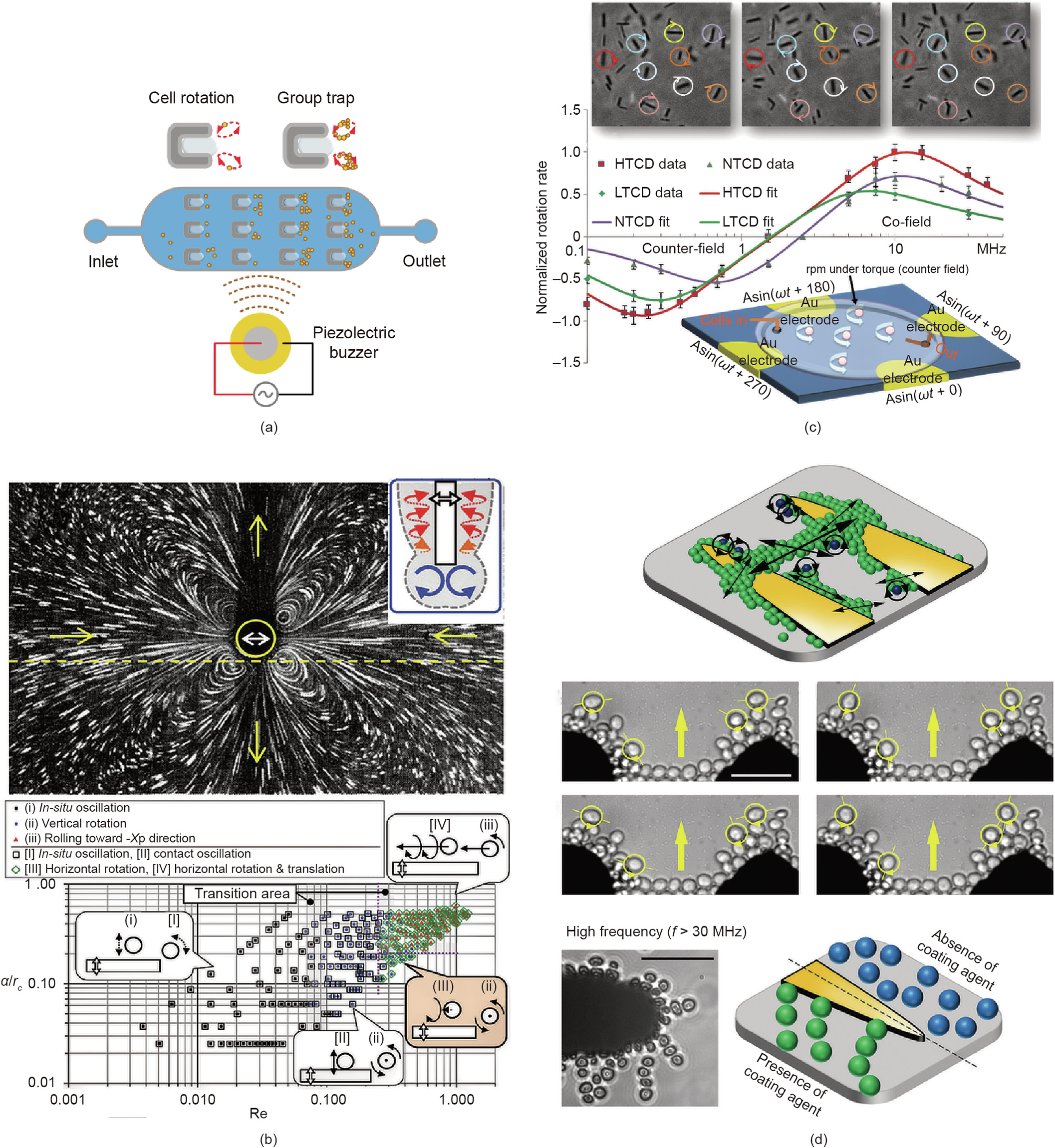
Fig. 8. Multi-cell rotation control activated by either acoustic or hydrodynamic forces. (a) The rotation speed of multiple cells is controlled with a pattern of four electrodes at different time points; (b) bubble-induced multi-cell rotation; (c) location-dependent multi-cell rotation is derived by hydrodynamic force around a micropipette; (d) the localized motion of patterned cell clusters under the influence of DEP. a: half of the oscillation’s amplitude; Re: Reynolds number; rc: cylinder’s radius. HTCD: high toxigenic Clostridioides difficile; NTCD: non-toxigenic Clostridioides difficile; LTCD: lowtoxigenic Clostridioides difficile. Adapted from Ref. [163] with permission of PMC, ©2019; Ref. [34] with permission of Biomedical Microdevices, ©2020; Ref. [154] with permission of Springer Nature, © 2018; and Ref. [101] with permission of American Chemical Society, © 2015.
Compared with acoustic-hydrodynamic manipulation, electrorotation has better spatial resolution (0.1–1 μm). When AC fields over a wide-frequency range (50–30 MHz) are applied on quadrupole-patterned electrodes, the cells activated by the rotating electric fields show co- or counter-field rotation at different velocities corresponding to the field strength. This rotation mechanism has been applied to realize the rapid assessment of the antibiotic susceptibility of pathogenic microbes, by multiplexing and automating parallel testing of multiple drugs [163] (Fig. 8(c)). However, it is obvious that all samples are randomly distributed in the rotating electric field, and some of them may collide with each other during the rotation, resulting in the failure of multi-cell analysis in parallel. In order to rearrange all cells, Soffe et al. [101] found that, as the exciting voltage frequency was increased to greater than 30 MHz, cell chains elongated and the intercellular distance between the cells increased, leading to the formation of loosely joined cell chains along the direction of the electric field (Fig. 8(d)). These researchers were able to control the rotation of cell clusters on the outer layers of rearranged cell chains. Such rotational motion can be modulated by adjusting the frequency and voltage of the applied sinusoidal AC signal. In this case, although cells are unlikely to collide with each other, the rotation speed varies over a wide range and only cells in the outer layers can rotate. Given the fact that this is the only recently reported successful electric field multi-cell rotation, and that the rotational motion of most cells in a large group is not controllable under DEP, in this review, we labeled the electric field as a single-cell rotation technique, as shown in Fig. 1(a).
In order to achieve highly efficient multicellular analysis, the manipulation technique must have the ability to rearrange and rotate cells simultaneously. OTs may have the potential to meet both requirements. This is because a laser beam can be split into multiple components using a computer-generated hologram [164], with complete control over the focal positions of each individual beam, and each split optical beam functions as an ‘‘optical finger,” enabling the rotation of multiple cells. The number of cells under control is only restricted by the number of split beams, which is generally around 100. Furthermore, these optical fingers are able to form optical traps at desired locations and rearrange a group of cells to avoid collisions between individual cells, thus contributing to the high spatial resolution of the manipulation. So far, however, there are only a few studies on the use of multiple laser beams for multi-cell rotation, possibly because of the optical damage caused to cells.
《4. Conclusions and perspectives》
4. Conclusions and perspectives
In this article, we reviewed six main subgroups of approaches for cell reorientation and high-speed rotation based on noncontact fields or micro-robotics. The advantages and disadvantages of these methods are summarized in Table 5 [4,9,16,17,46-48,52, 56,57,67,99-101,118-120,136,152,159,160,165,166]; the choice of a proper approach depends on the specific requirements for an application.
《Table 5》
Table 5 Summary of approaches for the rotation of particles (both biological and synthetic).

For the precise reorientation of smaller cells (i.e., < 100 μm) to a specific angle, optical-field-based approaches are the most suitable choice due to their non-contact manipulation. In addition, their controllability and precision can be further improved with the aid of surgical robotic systems and enclosed control systems. In order to minimize direct laser irradiation and decrease the risk of photo-damage to cells (Table 2), laser-based non-direct approaches or mechanical contact (for cells smaller than 100 μm) can be employed to reorientate target cells. In regard to magnetic-based approaches, only one successful report has realized cell orientation in an all-closed microtube, and researchers have not yet experimentally realized cell analysis on an open chip. Such noninvasive approaches are not yet available for the reorientation of cells or other specimens [134], and more efforts are required to develop them.
A rotating cell has advantages for cell imaging because it presents zero blind spots during cell observation. Hydrodynamic field approaches are quite popular for controllable cell rotation, as they cause no unwanted physical or chemical disturbances. When using hydrodynamic force, the rotation speed becomes increasingly fast with increasing controllability of the rotational direction and axis. By integrating a hydrodynamic field with an acoustic field to form acoustic tweezers in microchannels, the rotation of multiple samples in parallel was achieved, which potentially accelerates the imaging and analysis of the rotational patterns of a large number of samples. The rotational patterns of particles or bio-samples show some differences according to their physical features, such as weight and shape, but cell sorting based on the observation of rotating patterns has not yet been verified.
For single-cell analysis, numerous experiments [36,107] have shown that the dielectric properties of cells can be measured by electric tweezers, as the dielectric properties (e.g., the conductivity and dielectric constant) of cells are directly associated with the rotation speed and direction in a nonuniform electric field. Electric tweezers have been applied for the development of rotary nanomotors [167], achieving continuously tunable rotation of up to 16 000 rotations per hour. The research reported in Ref. [167] also realized the same control for multiple nanomotors. However, similar studies on cells still remain at the single-cell analysis level. For multiple cell rotation, the popular methods are still the hydrodynamic field or acoustic field approaches, both of which lack the ability to precisely control cells and are only suitable for multiangle cell imaging.
We have summarized various methods used for the rotation and orientation of single or multiple cells, but relatively few examples realizing parallel multi-cell rotation can be found, possibly because it is difficult to precisely rotate a group of cells under specific torques. In fact, there is an urgent need for this technique, since the rotational motion of cells is associated with the cellular state and with certain biophysical properties. To date, both AC electrokinetic-based microfluidic platforms and robot-aided multi-OTs are promising tools to meet the requirements for parallel rotation control, and we predict that the outcomes of research into them will be interesting and helpful in effectively accelerating the analysis of a large group of cells and distinguishing heterogenous cells based on their rotational features.
《Acknowledgements》
Acknowledgements
This work is supported by JSPS Grant-in-Aid for Scientific Research (20K15151), Australian Research Council Discovery Projects (DP200102269), JSPS Core-to-Core program, Amada Foundation, and White Rock Foundation.
《Compliance with ethics guidelines》
Compliance with ethics guidelines
Tao Tang, Yoichiroh Hosokawa, Takeshi Hayakawa, Yo Tanaka, Weihua Li, Ming Li, and Yaxiaer Yalikun declare that they have no conflict of interest or financial conflicts to disclose.


 京公网安备 11010502051620号


