《1. Introduction》
1. Introduction
Over the years, antenna design for mobile terminals has become increasingly difficult. This is mainly attributed to the limited space available in such devices for the housing of multiple antennas with wide and multi-frequency band requirements. The coming fifth generation (5G) of wireless communications makes this issue even more challenging for mobile terminal antenna designers, since it requires a very large number of multiple input/multiple output (MIMO) antennas at sub-6 GHz frequency bands, as well as two or three antenna-in-package (AiP) modules at millimeter-wave frequency bands. In these antenna designs, the antennas must be small, compact, low profile, and lightweight, while maintaining wideband and multiband performance. Furthermore, for MIMO antenna design, although the antennas are placed very close together, a high degree of isolation between antennas must be satisfied, even within the same frequency bands. This article presents an overview of future antenna design for mobile terminals.
《2. Antenna design environment and requirements》
2. Antenna design environment and requirements
Mobile terminals typically include smartphones, laptops, tablets, mobile wireless fidelity (MiFi), data cards, smart watches, Bluetooth (BT) headsets, routers, the Internet of Things (IoT), smart screens, customer premises equipment (CPE), augmented reality (AR) devices, virtual reality (VR) devices, and automobiles. Antenna design technology for mobile terminals has a very significant impact on mobile terminals’ industrial design (ID), architectures, battery capacity, talking and idle time, user experience, market access, communication capacity, and legal requirements. It is generally believed that the design of smartphone antennas is the most challenging task for antenna engineers, due to smartphones’ sleek IDs, highly integrated architectures, and interaction with the human body. Fig. 1 shows a simplified antenna design environment of a smartphone, which comprises a metal frame, a printed circuit board (PCB)/display metal panel, a battery, and several components including a universal serial bus (USB), a subscriber identification module (SIM) card holder, an audio-video (AV) jack, a power key, and a volume key. The gap between the metal frame and the PCB/display metal panel is usually less than 1.0 mm in order to achieve a large screen-to-body ratio. There are a number of connection points between the metal frame and the PCB/display metal panel to create grounding points for the antennas. The metal frame can be cut to form a few opening slots, giving the antenna radiator a short circuit at one side and an open circuit at the other side, in order to reduce the antenna sizes from a half wavelength to a quarter wavelength and improve the antenna bandwidth and efficiencies. For a 5G smartphone, the required antennas are:
• Multiband main antenna: long-term evolution (LTE)/new radio (NR) (698–960 and 1710–2690 MHz);
• Multiband diversity antenna: LTE/NR (698–960 and 1710– 2690 MHz);
• 4 × 4 MIMO antennas: LTE/NR (1710–2690 MHz);
• 4 × 4 MIMO antennas: NR (3300–5000 MHz);
• Global navigation satellite system (GNSS) antennas: GPS/GLONASS/Galileo/BeiDou (1176 and 1575–1609 MHz);
• Triple-band 2 × 2 MIMO antennas: wireless fidelity (WiFi) (2400–2484, 5150–5350, and 5725–5825 MHz);
• Three dual-band ultra-wideband (UWB) antennas: UWB (6240–6740 and 7750–8250 MHz);
• Two or three millimeter-wave AiP modules: AiP (24.25–29.50 and 37.00–43.50 GHz);
• Near-field communication (NFC) antenna: NFC (13.56 MHz).
《Fig. 1》
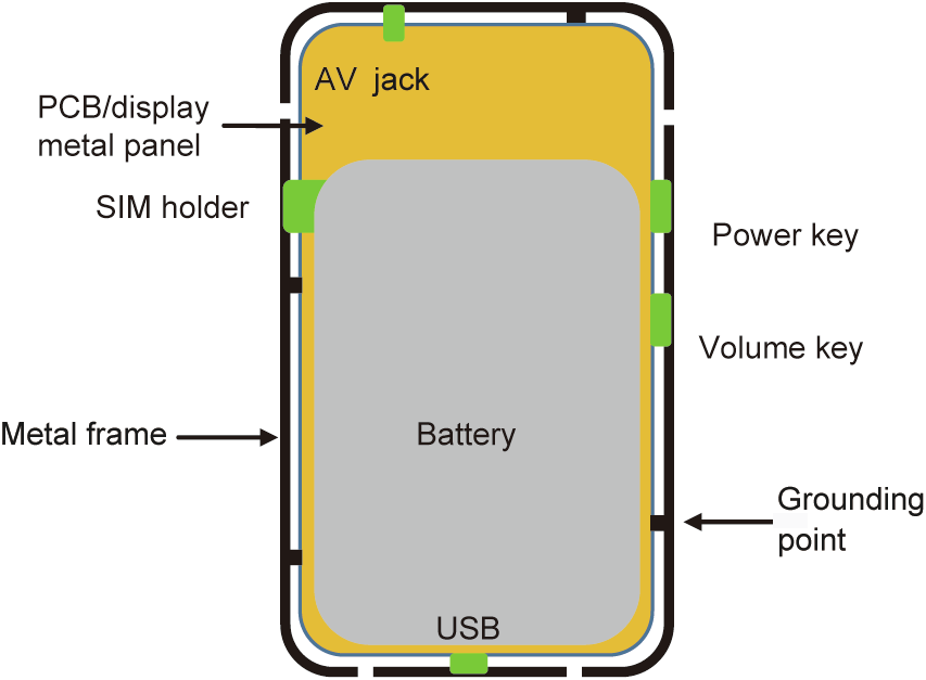
Fig. 1. Simplified antenna design environment of a smartphone. PCB: printed circuit board; SIM: subscriber identification module; USB: universal serial bus; AV: audio–video.
The total number of antennas is 15–20, and this number could be increased further to 25–30 if carrier aggregation (CA)/E-UTRAN new radio–dual connectivity (ENDC) and 8 × 8 MIMO are implemented. Apart from the large quantity of required antennas, all the antennas must meet the relevant design specifications, which include bandwidth, efficiency in free space, in hand and beside head with hand, isolation between antennas, power spectrum density (PSD), and specific absorption rate (SAR). The metal frame generally acts as the optimal antenna radiator for most of the antennas, due to its metallic size and off-ground location, especially for the LTE/NR main and diversity antennas at the low and middle bands. On-ground antennas, such as planar inverted-F antennas (PIFA), patches, and millimeter-wave AiP modules, can be placed above the PCB/display metal panel or on the back side of a battery cover; however, the operating frequencies of these antennas generally need to be higher than 3.0 GHz to guarantee good performance, since the height of these antennas is usually no more than 1.0 mm. Furthermore, optically transparent antennas can be placed on mobile terminal displays to reduce the human body’s impact on antennas’ performances and improve the coverage of antenna radiation patterns [1].
《3. Antenna concepts of mobile terminal antennas》
3. Antenna concepts of mobile terminal antennas
As depicted in Fig. 2, the conventional antenna concepts of mobile terminal antennas can be classified as ① inverted-F antennas (IFAs)/PIFAs [2], ② monopole antennas [3], ③ loop antennas [4], ④ composite right/left-handed (CRLH)-inspired antennas [5], and ⑤ monopole slot antennas [6]. The operating principles of these antennas are well documented in these references and in Refs. [7,8]. In addition to the conventional concepts, reconfigurable antennas—mainly frequency reconfigurable antennas [9]—have been extensively utilized in mobile terminal antenna designs to extend their impedance bandwidth. Antennas with pattern and polarization reconfigurable features are also becoming increasingly intriguing for MIMO applications [10].
Unlike antenna design for base stations, airborne radars, and many other types of communication equipment, there are few systematic theories and sophisticated approaches for designing antennas for mobile terminals, even as this task becomes increasingly complex and challenging, particularly for future mobile terminals. The reason is that the widely used antennas for mobile terminals, as illustrated in Fig. 2, operate as common modes (CMs). These common-mode antennas radiate dominantly through their ‘‘environment”—namely, the metallic components directly and indirectly connected to the antennas, such as the PCB and all the metallic parts within the whole mobile terminal. In comparison with any other antennas associated with dominantly differential modes (DMs), the main benefits of utilizing CM in the design of mobile terminal antennas include smaller antenna size, larger radiation aperture, wider impedance bandwidth, and higher radiation efficiency. The penalty is the difficulty of controlling antenna radiation patterns. However, since the orientation of a mobile terminal can be arbitrary, antenna radiation efficiency is more crucial than antenna radiation pattern in mobile terminal antenna design. This is mirrored by the required over-the-air (OTA) performance comprising the total radiated power (TRP) and total radiated sensitivity (TRS), which are defined by a radio frequency (RF) front end’s conducted power and conducted sensitivity, respectively, in conjunction with antenna radiation efficiency. Due to the introduction of CM and ‘‘environmental” radiation, the complexity and difficulty of designing mobile terminal antennas are significantly increased.
《Fig. 2》

Fig. 2. Conventional concepts of mobile terminal antennas. IFA: inverted-F antenna; CRLH: composite right/left-handed.
As described in Section 2, for the antenna design of a smartphone, a very large number of antennas must be arranged in a very limited space. A conventional solution to this problem is to employ duplexers and multiplexers to design single-feed co-radiator antennas covering wide and multi-frequency bands. Apart from the antenna concepts outlined above, the concept of CM and DM for designing single-feed wideband and multiband antennas for mobile terminals has recently been proposed [11]. One of the most distinguishing features of the proposed antennas is to employ both CM and DM in the antenna design. In this proposed antenna concept, wire CM/DM and slot CM/DM unit antennas are defined, where the antenna units must be placed or fed asymmetrically in order to achieve wideband or multiband features. In contrast to all the other antenna concepts for mobile terminal antennas, wire DM and slot DM—namely, a half-wavelength dipole mode and a half-wavelength slot mode—have been introduced to create additional resonances so as to increase the bandwidth. Higher order modes could also be excited to further improve the bandwidth of the antennas. As the design approach of the proposed wire CM/ DM and slot CM/DM is more rigorous and systematic than conventional approaches, it is expected that it will have a significant impact on and wide applications in the antenna design of future mobile terminals.
For a typical 5G NR MIMO antenna design, two antennas operating at the same frequency bands are needed, while high isolation between the two antennas must be satisfied, despite the usual close placement of the antennas due to the very crowded design environment. It is obvious that this design difficulty cannot be circumvented by utilizing filters, duplexers, and multiplexers. To save antenna volume and to place more antennas in a limited space, a concept of designing the two antennas in a pair was proposed [12], and good isolation was obtained by using the principle of complementary current distributions. An orthogonal mode design approach was proposed to further address this problem [13]. The two antennas in the antenna pair have orthogonal polarization when they are located symmetrically, and good isolation between the two antennas has been achieved. Another major step is the explicit definition of the CM/DM concept in the design of an antenna pair having the same frequency bands and high isolation [14,15], although the orthogonal polarization feature is to some extent similar to that in Ref. [13]. However, in all the antenna pairs mentioned above, the two antennas are either a wire type or a metal sheet type. A more comprehensive and symmetrical concept has been proposed in Ref. [16]. In this antenna concept, four unit antennas are defined: wire CM, wire DM, slot CM, and slot DM. Therefore, there are six pair combinations resulting from the four unit antennas. Among the six combined antenna pairs, four are antenna pairs with an inherently high isolation property, thanks to their orthogonal polarization, while the other two can also obtain a high degree of isolation if one of the antennas in the pair is rotated by 90°. This proposed antenna design concept has significantly increased the degrees of freedom—namely, from one to six—for designing 5G NR MIMO antennas. Two design examples of the six combined antenna pairs can be found in Refs. [17,18].
The commonly used UWB antennas are antennas with flexible substrates, which are placed above the PCB/display metal panel, with low-loss liquid crystal polymer (LCP) or modified polyimide (MPI) as antenna substrates. The design of the UWB antenna is typically a dual-band PIFA or offset-feed dual-band patch antenna. As its operating frequency is above 6000 MHz, a 0.3–0.4 mm antenna height is sufficient to cover the required frequency bands. The design of millimeter-wave AiP modules is similar to the design of a conventional phased antenna array. Usually, an AiP module is a patch antenna array or a magneto-electric (ME) dipole [19] array with 1 × 4 or 2 × 2 antenna elements having orthogonal dual polarizations. The challenge for this antenna array design is to meet the strict requirements of wideband, multiband, high gain, wide scanning angle, small size, and low height. The conventional solution to the NFC antenna in a smartphone is to share a section of the metal frame radiator with a cellular antenna, using a hybrid distributed/lump inductor as a low-pass filter. Other solutions for NFC antennas include a ferrite sheet with coils, or coils in conjunction with the metal cover of the mobile terminal [20].
《4. Summary》
4. Summary
Antenna design for future mobile terminals, especially for smartphones, is facing huge challenges due to the very limited space, large number of antennas, and very stringent design requirements and specifications for such devices. The CM/DM antenna concepts for single-feed and dual-feed antennas provide comprehensive and systematic solutions to the design of wideband, multiband, and 5G NR MIMO antennas. These concepts will find wide applications in the area of antenna design for future mobile terminals.


 京公网安备 11010502051620号


