

《1 Introduction》
1 Introduction
The durability of tunnel lining structure is related to time, which is the number of years of normal use of engineering structures from the joint action of the lining structure (such as soil and water load, geological condition, corrosion type, etc.) and its own factors (joints, cracks, leakage, and pore structure). A major feature of the shield tunnel is that it is in a high-pressure seawater environment for a long time unlike city tunnels and mountain tunnels. There are the influence of high concentration of chloride ion and the external pressure of the tunnel on the shield tunnel, thereby worsening the service environment of the submarine tunnel. In addition, shield tunnel segment lining has its own weak joint links, which results in enormous challenges in terms of the durability and long-term safety performance of a submarine shield tunnel.
Several scholars have conducted studies on the durability of tunnel structure in sea environment [1–5]. However, these studies mainly focused on the evaluation of the mechanical properties and corrosion deterioration characteristics of lining structures, and did not take the influence of the tunnel service time into consideration. Quantitative evaluation and life prediction of tunnel structure in the entire life cycle is difficult to implement. In view of this, the weak link in the structure of the shield tunnel, namely the segment joint, was considered as the starting point in this study. Existing research results on segment joint erosion deterioration were analyzed, and the tunnel service time factor was introduced to develop an analysis model for the entire life erosion deterioration of segment joint due to seawater pressure osmosis and chloride ion erosion. The law of progressive erosion deterioration of subsea tunnel segment joints in the entire life cycle of 100 years was analyzed. The effects of seawater pressure and chloride content on erosion and deterioration of segment joints were investigated. The most economical and reasonable countermeasures were proposed to ensure long-term safety of the segment lining structure of a submarine shield tunnel based on the entire life erosion deterioration analysis.
《2 Study on erosion deterioration of typical segment joints》
2 Study on erosion deterioration of typical segment joints
Presently, few studies have been carried out on chloride erosion segment joints. Durability and corrosion protection experiments were conducted by Gongteng Quan [6] for the shield tunnel joint of the Dongjing Bay to investigate the corrosion resistance of bolts after surface treatment. Three types of bolts were installed during the test: ① ordinary bolts; ② ordinary steel bolt coated with zinc powder tyroic acid protective film; and ③ ordinary steel bolts coated with ethylene fluoride resin. The three bolts types were tested using brine spray for 90 days. The results show that the material quality of bolt types ① and ② did not change with corrosion resistance. The corrosion resistance exposure time of bolt types ② and ③ in different environments obtained based on calculation of the amount of test corrosion equivalent to 30 to 50 years of corrosion resistance in heavy industrial areas is presented in Table 1.
《Table 1》
Table 1. Exposure time of bolts in different environments.

Yang et al. [7] carried out theoretical analysis of the effect of crack and joint leakage on erosion and migration of chloride ion in tube concrete in Matlab environment. The relationship between the rusting time of a steel bar, the thickness of the protective layer, and the depth of the crack was obtained using multi parameter analysis and data fitting. Furthermore, the accelerated effect of segment cracking and joint leakage on the corrosion of the steel bar was obtained.
Wang [8] categorized the lifetime of chloride ion erosion period into three stages: chloride ion diffusion stage, steel corrosion stage (free expansion, expansion stress generation, concrete cracking), and the cracking stage of the protective layer. The durability of the subsea tunnel was further analyzed and the durability life prediction model of a submarine tunnel was derived. Furthermore, the results were compared with those obtained from the DuraCrete model as presented in Table 2. It can be observed that the results of the prediction model are in agreement with those of the DuraCrete model.
《Table 2》
Table 2. Comparison of results between the DuraCrete model and prediction model.

A thorough review of the above studies reveals that none of the existing studies took into account the influence of seawater pressure osmosis on the environment of the undersea tunnel (Fig. 1). As the carrier of corrosion ion erosion migration, seawater creates segmental concrete in a slow seepage state under the action of pressure head during the entire life cycle. Segment concrete evolves gradually from the “unsaturated state” to the “saturated state” from outside to inside. In addition, the joint surface of the segment joint is in a state of bidirectional penetration erosion in the weak link and priority position of the subsea tunnel structure. Corrosion deterioration performance in the entire life cycle has significant impact on maintenance and long-term safety performance of the entire shield tunnel lining structure. Therefore, a factor of service time was introduced and an analysis model was developed, which takes the influence of seawater pressure permeation and erosion environment into consideration in the analysis of the entire life erosion deterioration of the segment joint.
《Fig. 1》

Fig. 1. Working environment of subsea shield tunnel segment structure.
《3 Model of entire life erosion deterioration of segment joint》
3 Model of entire life erosion deterioration of segment joint
This section focuses on the weak link of the seabed shield tunnel structure, namely the segment joint. A numerical analysis model of chloride ion degradation during the life cycle of segment joints was developed using GeoStudio finite element software, as shown in Fig. 2.
《Fig. 2》
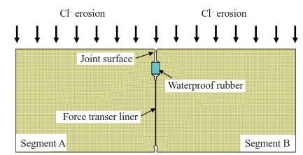
Fig. 2. Erosion deterioration analysis model of segment joint during its life cycle.
The numerical analysis model adopted the “straight instead of the curve” method. The straight beam segment member was used for the simulation. The influence of the joint surface position of the segment joint on chloride ion erosion and reinforcement corrosion of segment A and segment B on both sides was analyzed. In the calculation and analysis process, the transient seepage model was first used. The seepage evolution law of the adjacent region of the segment joint in the entire life cycle under different water pressure conditions was analyzed using the transient porous flow model. The law of erosion deterioration in the adjacent region of the segment joint was analyzed using the convection–dispersion analysis method for the entire life cycle under different water pressure conditions and different external ion concentration values.
The material of the model was uniform, continuous, and isotropic, of which waterproof rubber and force liner are all impervious materials. According to the relation between the impermeability grade and permeability index [9,10], the permeability coefficient, k and volume water content, w of segment concrete (impermeability grade P12) are 1.11456×10⁻⁶ m·d−1 and 0.001, respectively, while the volume compressibility is 1.0×10⁻⁶ kPa, the horizontal and longitudinal dispersion is 0.04, and the chloride ion diffusion coefficient is 4.8×10⁻¹² m2 ·s−1.
《4 Analysis of entire life erosion deterioration of segment joints》
4 Analysis of entire life erosion deterioration of segment joints
《4.1 Law of seawater permeation inside a tube》
4.1 Law of seawater permeation inside a tube
In the entire life cycle, segment concrete evolves gradually from the “unsaturated state” to the “saturated state” from outside to inside in a state of slow seepage. The relationship between the seawater penetration depth and time in segment concrete is shown in Fig. 3. The figures shows that the permeation depth of seawater in concrete segments increases as the service time of the segmental lining of the subsea tunnel increases. Under the same conditions, the higher the external water pressure on the lining section, the higher the degree of seawall infiltration erosion.
《Fig. 3》
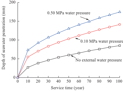
Fig. 3. Relationship of seawater penetration depth with time under different water pressure conditions.
《4.2 Variation law of ion content》
4.2 Variation law of ion content
According to the structural characteristics of shield tunnel, the position of the joint surface is in a state of bidirectional erosion and permeation. The distribution of the ion content at a nearby position exhibits local transverse and longitudinal inhomogeneity. The evolution law of erosion deterioration in the entire life cycle of segment joints was analyzed by selecting the monitoring points at different positions (Fig. 4).
《Fig. 4》

Fig. 4. Schematic diagram of regional monitoring points for segment joints (unit: mm).
4.2.1 Influence of erosion deterioration on the position of joint surface of external water pressure butt joint
Consider section A, adjacent to the joint surface of the segment; the erosion degradation of the proximal end of the segment joint when the chloride content on the outer surface of the segment is 0.6% is shown in Fig. 5.
《Fig. 5》

Fig. 5. Distribution curve of chloride ion content near the end of a tube joint.
As shown in Fig. 5, as the service time of the tunnel segment lining structure increases, the chloride ion content at the joint surface of the segment increases continuously. This indicates a large increase in the measuring points on the outer surface of the proximal segment. The growth and increase of chloride ion content at sites A- ① and A- ② near the outer surface is obviously larger than that near the inside of the segment at sites A- ⑤ and A-⑥. We can find that the law of erosion deterioration under different external water pressure conditions. The higher the external water pressure, the higher the chlorine ion content in the same position of the segment. When the external water pressures are 0.10 MPa and 0.50 MPa, the chloride content at site A- ⑤ at 100 years old are 0.05659 % and 0.3076 %, respectively. It can be observed that an increase in the external water pressure can promote chlorine ion erosion inside the segment; the closer it is to the outer surface of the segment, the more obvious the effect of high water pressure.
4.2.2 Difference in the distribution of chloride ions between the proximal and distal ends of segment joint
Consider an external water pressure of 0.50 MPa; the degradation law of ion erosion at the proximal and distal ends of the segment joint is obtained as shown in Fig. 6.
《Fig. 6》

Fig. 6. Distribution curve of chloride ions at different positions in the segment.
As shown in Figs. 5 and 6, when the external water pressure is fixed, the distribution of chloride ion content is different depending on the joint surface distance. The closer it is to the joint surface of the segment, the higher the chloride ion concentration inside the segment. At 50 years of service and at approximately position ④ , which is 25 mm (Fig. 5(c)), 75 mm (Fig. 6(a)), and 175 mm (Fig. 6(b)) from the joint face, the chloride contents are 0.344 %, 0.202 %, and 0.126 %, respectively. The distribution curve of chloride ion content at each measuring point at the position of 375 mm from the joint surface (Fig. 6(c)) coincides with that at 175mm. It can be observed that the closer to the joint surface, the higher the chloride ion content, which reflects the transverse heterogeneity of the chloride ion content distribution. On the same distance from the joint surface, such as positions ① , ② , ③ , ④ of A=25 mm from the joint surface, the chloride contents are 0.59 %, 0.58 %, 0.54 %, and 0.46 %, respectively at 100 years. The distribution of chloride ion content reflects the characteristics of gradual decrease with the increase in the depth, and the longitudinal inhomogeneity of chloride ion content.
4.2.3 Influence of external corrosion ion concentration change
Consider an external water pressure of 0.50 MPa; the law of ion erosion deterioration at the joint surface (section A) of the segment is obtained under different external corrosion ion concentration conditions as shown in Fig. 7.
《Fig. 7》

Fig. 7. Distribution curve of chloride content in the segment under different chlorine concentration conditions.
It can be observed from Fig. 7 that when the external chlorine concentration of the segment is different, the content of chlorine ions inside the segment varies with the location for the entire life cycle. When the chloride ion contents on the surface of the segment are 0.5 %, 0.6 %, and 0.7 %, the chloride ion contents at A- ① measurement point for 100 years are 0.5 %, 0.6 %, and 0.7 %, respectively, while the chloride ion contents at A- ⑥ are 0.12 %, 0.14 % and 0.16 %, respectively. Thus, the change in the internal chloride ion content is not obvious at A- ⑥ site.
It can be observed that increasing the content of chlorine ions on the surface has significant effect on the content of chlorine ions near the outer surface of the segment. As the depth of chloride ion erosion increases, this effect is gradually weakened. When the content of chlorine ions on the surface is different, the trend of the change curve of chloride ion content is the same. The time taken to achieve the same content at the same location is different. When the chloride ion contents on the surface of the segment are 0.5 %, 0.6 %, and 0.7 %, the times required to reach 0.2 % at A-④ site are 34 years, 29 years, and 26 years, respectively. It can be observed that increasing the concentration of chloride ions on the outer surface of the tube can shorten the erosion time of the accumulation of chlorine ions near the outer surface to the same chlorine ion content.
《5 Safety countermeasures of submarine shield tunnel segment structure based on life degradation analysis》
5 Safety countermeasures of submarine shield tunnel segment structure based on life degradation analysis
《5.1 Analysis of corrosion and deterioration of steel bars in the entire life cycle》
5.1 Analysis of corrosion and deterioration of steel bars in the entire life cycle
For the reinforced concrete subsea tunnel segment lining, the main sign of deterioration in the entire life cycle is corrosion of the steel bar inside the segment. According to references [11,12], the corrosion of the steel bar is based on the chloride ion concentration of 0.4 % on the surface of the steel bar. Based on this, the distribution of chloride ion content at different measuring points (Fig. 8) is obtained for chloride ion content of 0.6 %, as shown in Fig. 9.
《Fig. 8》

Fig. 8. Schematic diagram of monitoring points of steel bar drainage area.
《Fig. 9》

Fig. 9. Distribution curve of chloride content at different positions of steel bars.
The corrosion results of steel bars in Fig. 9 show that the chloride content at a position on the steel bar outside the segment continuously accumulates with the prolongation of the service time when water pressure is not considered. However, the point where the corrosion of the steel bar is observed is only at position ① adjacent to the joint surface of the segment. As shown in Fig. 9 (a), if the influence of water pressure is not considered, the weakening effect of the segment joint (the state of bidirectional penetration erosion at the joint surface) is only reflected in the area where the joint surface of the segment is smaller. The influence of the steel bar on the distal end of the joint surface is small; on further analysis, it was found that because the joint surface of the segment joint is in the state of bidirectional penetration erosion, longitudinal non-uniform corrosion is reflected in the direction of the reinforcing bar outside the segment. When the water pressure on the outside of the segment is 0. 50 MPa, the corrosion times of the steel bar at ① and ⑦ are 7 years and 28 years, respectively. It can be observed that the increase in the water pressure accelerates corrosion and deterioration of the steel bar. When the pressure permeation of the external water pressure is taken into consideration and there is no external hydraulic pressure (Fig. 9(a)), steel corrosion occurs only at this point. However, with the increase in the water pressure (as shown in Fig. 9(b) under water pressure of 0.10 MPa), corrosion occurred at points ① –⑦ . The corrosion times at sites ① and ⑦ are 8 years and 72 years, respectively. When the water pressure increases to 0.50 MPa (Fig. 9(c)), corrosion occurs at all measuring points (① –⑦) after 28 years of operation, and the time of rust initiation is significantly advanced.
Furthermore, we analyzed the erosion degradation law at different external water pressure conditions and different steel bar positions in the entire life cycle. With the increase in the water pressure outside the segment, the erosion rate of chloride ions increases (the curve is steep and the slope is large), and the magnitude of the maximum chloride content becomes greater after 100 years of service. It is indicated that the water pressure promoted the corrosion of the corrosive ions. When the external water pressure is small or no pressure, the maximum chlorine ion content is in the range of 0.05 %–0.6 %, and varies significantly at different positions of the steel bar. However, as the external water pressure increases, the difference in the chloride ion content at different positions of the steel bar decreases. For example, under high water pressure of 0.50 MPa, the maximum ion content at different positions of the steel bar is in the range of 0.54 %–0.6 %, and the uneven difference is small. It can be observed that the difference in the inhomogeneous corrosion and deterioration in the direction of the reinforcement is obviously reduced by the increase in the external water pressure.
《5.2 Safety countermeasures for segment structure of submarine shield tunnel》
5.2 Safety countermeasures for segment structure of submarine shield tunnel
The segment joint in the segment lining structure of submarine shield tunnel is the weak link of the entire lining structure. It easily becomes the primary position for high water pressure and corrosion ion erosion degradation. Erosion and deterioration analysis was carried out in the entire life cycle, and it was found that the joint surface of segment joint has a limited influence on both sides of the joint and does not affect the entire segment lining structure.
As shown in Fig. 9, progressive erosion deterioration occurs during the entire life cycle of the segment lining structure under high water pressure and seawater corrosion environment. The corrosion and deterioration process at measuring points ⑥ and ⑦, far away from the joint surface of the segment joint, is almost synchronous. The corrosion time of the steel bars is the same and they are in the state of unidirectional osmotic ion erosion migration. The influence of the joint of the segment joint on the weakening of the lining structure of the segment can be neglected. However, the positions of measuring points ① – ⑤ are affected by the weakening of the joint surface of the segment joint under the action of local bidirectional penetration erosion of the segment joint. The corrosion time of the steel bar varies and decreases with decreasing distance from the joint surface. According to the position relation of the measuring point, the connection of the segment joint can be determined. The influence range of the joint weakening is approximately within the range of the distance between the joint surface and the joint surface equal to the thickness of the segment, as shown in Fig. 10.
《Fig. 10》

Fig. 10. Sketch of corrosion resistant range of joints in submarine shield tunnel segments.
Therefore, to meet the requirement of safe service in the entire life cycle of submarine shield tunnel between the weak link of the segment lining and the two sides of the segment joint (which is equal to the thickness of the segment), corrosion resistance fortification design and maintenance are carried out to improve corrosion resistance and long-term safety performance of the entire tunnel lining structure. In addition, according to the relation of the time between the accumulation of reinforcement and the critical concentration of corrosion ion, which positively correlates with the thickness of the concrete cover, the larger the thickness of the protective layer, the higher the chloride ion erosion time. It is also possible to increase the thickness of the concrete cover to delay the corrosion of the steel bar and to ensure safety of the tunnel structure as shown in Fig. 11.
《Fig. 11》

Fig. 11. Sketch of reinforced protective layer thickness in submarine shield tunnel segments.
Owing to the interaction of soil and water load, surrounding chlorine ion erosion, and internal operating environment, the safe load-bearing performance of the monolithic segment lining structure will deterioriate slowly in the entire life cycle. In addition, the shield segment lining structure belongs to the multibody splicing structure composed of segments. The structure itself has its own segment joint weak link. The cost of tunnel construction and maintenance will be significantly increased if the overall durability and anticorrosion protection, as well as maintenance of the entire tunnel section are carried out.
Based on the above results, the most economical and reasonable countermeasure can be implemented in the limited area of the segment joint (Fig. 12 and Fig. 13) by improving the anti-seepage grade of concrete in the range of corrosion resistance, adding anticorrosive coating on the outside or both sides of the regional segment, increasing the thickness of the concrete protective layer appropriately, and so forth. These are the most economical and reasonable schemes to increase the difficulty of the erosion of corrosion ion to the dangerous area and to delay the rate of corrosion in the steel bar, thereby improving the safety reserve capacity of the segment lining structure under the coupling of multiple environments such as high water pressure environment, complex ion erosion environment, and internal operating environment in the entire life cycle in order to delay the adverse effects or weakening of multi-environment coupling on the tunnel lining structure, improve the durability of the integral segment lining structure, and provide effective technical guarantee for the safety of submarine shield tunnel.
《Fig. 12》
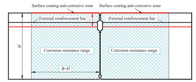
Fig. 12. Sketch of security countermeasures of joints in submarine shield tunnel segments.
《Fig. 13》

Fig. 13. Sketch of countermeasures of structural safety in submarine shield tunnel segments.
《6 Conclusions》
6 Conclusions
the segment joint, was considered as the starting point in the analysis model of life erosion deterioration of segment joint to evaluate seawater pressure infiltration and chlorine ion erosion migration. The law of erosion deterioration of subsea tunnel segment joints in the entire life cycle of 100 years was analyzed. The adverse effects of high water pressure and chloride ion erosion on the erosion deterioration of the shield tunnel under sea surface were clarified. Based on the analysis of erosion deterioration in the entire life cycle, the most economical and reasonable critical area of corrosion resistance and maintenance of undersea shield tunnel lining structure was proposed. By carrying out local improvement of impermeability of concrete in the fortification range, adding anticorrosive coating on the outside or both sides of the segment, and appropriately increasing the thickness of the concrete cover, the safety reserve capability of the segment lining structure can be improved under multienvironment coupling condition in the entire life cycle as well as counteracting the adverse effect of multi-environment coupling on the tunnel lining structure. Improving the durability of the overall lining structure provides an effective technical guarantee for long-term safety of the seabed shield tunnel.
Compared to the design and construction stage, the structure has the characteristics of long service period, complex environment, cumulative corrosion, and so forth in its entire life cycle. The shield tunnel lining in the coastal and marine environment is more prone to damage due to the long-term water rich environment in the city. The scientific evaluation and quantification of its structure and performance is particularly important and urgently required. How to guarantee the system reliability and long-term safety of a shield tunnel project remains a major technical challenge for Chinese scientists and technicians.


 京公网安备 11010502051620号


