
《1. Introduction》
1. Introduction
The semiconductor industry continued to follow the famous Moore’s Law when Intel introduced the revolutionary Tri-Gate transistors in its 22 nm logic technology in 2011 [1]. As semiconductor processes become more advanced and complicated, interest in finding alternative approaches for the smart manufacturing of transistors is increasing quickly. In 2000, an all-polymer transistor made of an organic semiconductor, conductor, and insulator using inkjet printing was reported [2], triggering an explosion of research into printed electronics. In general, two main aspects of the printed organic transistor arouse people’s interest: first, that a conventional mineral-based transistor can be made from organic materials; and second, that printing technology can be used to make electronic devices. Although the printed circuit board (PCB) is well established, it involves the printing of resist materials rather than of electronic materials. In the search for potential low-cost, large-scale, and fast ways to fabricate electronics, outstanding work has been done around the world. Such work can be summed up into two categories: namely, innovations in either printing strategies or in materials. Except for inkjet printing, most fabrication strategies are made possible by micro-contact printing, roll-to-roll printing, and screen printing [3]. To date, a variety of important and functional printing materials [4,5] have been intensively investigated. Among these, silver nanoparticle ink stands as perhaps the most frequently focused-on conductive ink. At this stage, major challenges in the development of silver nanoparticle ink lie in the high-temperature sintering or intense pulsed-light sintering required for the post-printing processes, its relatively large resistivity, and the potential breaking of printed wires. To overcome the need for a high-temperature sintering process, a type of reactive silver ink has been synthesized that only requires annealing at a mild temperature (90 °C) to obtain very high conductivity, as high as the conductivity of the bulk silver [6]. A new silver nanoparticle-based highly conductive ink has been proposed that has a built-in sintering mechanism, avoiding post-sintering completely [7]. However, most of these printing materials still suffer from other undesirable features such as a sophisticated fabrication process and complex printing conditions etc. Thus far, conventional electronics manufacturing strategies are gene-rally environmentally unfriendly; consuming too much time, water, and energy; and requiring overly expensive apparatus. To a large extent, these drawbacks have held electronics manufacturing back from wide-range applications in modern business, and particularly from applications for personal use. It has long been a dream in electronics manufacturing to be able to write out electronics directly, as simply as printing a picture onto paper using an office printer.
In order to provide a reliable and truly direct fabrication of electronics, our lab has proposed a fundamentally different strategy for direct electronics writing (or printing) through the introduction of a new class of conductive inks made of low-melting-point liquid metals or alloys. This method was later named “the Direct Writing of Electronics based on Alloy and Metal Ink,” and abbreviated as DREAM Ink [8]. Through tremendous efforts spent investigating a group of different printing principles over the past few years, the first-ever liquid-metal printer prototype for personal use was invented [3]. Using this machine, we have demonstrated printing out various electronically conductive patterns onto a series of either soft or rigid substrates with high resolution within a scale of 20–80 μm. These patterns range from a single wire to various complex structures such as an integrated circuit, an antenna, sensors, radio-frequency identification (RFID), electronic cards, decorative artwork, classical drawings, and other do-it-yourself (DIY) circuits. The entire process is as short as 15 min. This machine could significantly stimulate a worldwide level of personal practice in electronics manufacturing. Liquid-metal printing is quickly emerging as an excellent way to manufacture electronics at room temperature. As part of a continuous endeavor toward making a pervasive, high-quality, consumer-level printing machine for the coming society, this article presents the close-to-industrial manufacturing process of a liquid-metal printer and interprets its prospective value as an automatic, easy-to-use, and individual-oriented desktop electronics printing machine. The basic features, technical mechanisms, important applications, and potential future of this cutting-edge technology are explained here.
《2. Basic features of liquid-metal ink》
2. Basic features of liquid-metal ink
From its initial use in the thermal management of high-heat flux electronics [9], room-temperature liquid metal is emerging as a very useful material in a wide range of consumer electronics applications. The term “liquid metal” usually refers to modified gallium or a more alloy-based electronic ink, although many different low-melting alloys may possibly be used. The most typical material is GaIn24.5, a eutectic gallium and indium alloy containing a 75.5% mass fraction of gallium and 24.5% indium. GaIn24.5 has a melting point of 15.5 °C [10], which causes it to remain in a liquid state at room temperature (i.e., 20 °C) under normal conditions. Another extremely important quality of liquid-metal inks is that they are safe for human use, unlike mercury, which is well known to be toxic. In this study, we focus our discussion on liquid metals and alloys with melting points around room temperature, namely the GaIn24.5 alloy, which is uniquely important as a printing ink. Its naturally liquid phase and high conductivity (3.4 × 10⁶ Ω−1m−1) makes this metal fluid the most promising candidate for an electronics ink that is directly printable at room temperature [3].
It is common knowledge that water forms a droplet on a leaf but sinks into a dusty floor. On the other hand, mercury forms a droplet and rolls across a dusty floor rather than sinking into it. This difference between water and mercury is caused by wettability, which depends on intrinsic surface tension or surface energy. Generally speaking, a leaf has a greater surface tension than a dusty floor, and mercury has a greater surface tension than water. When a liquid drop rests on a flat, solid surface, the contact angle is defined as the angle formed by the intersection of the liquid-solid interface and the liquid-vapor interface (Figure 1).
《Fig. 1》
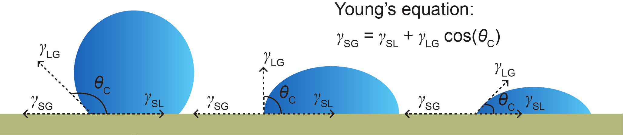
Fig.1 An illustration of Young’s equation and contact angles. The surface tensions of the solid and the liquid involved are denoted by γSG and γLG, respectively. When the two materials come in contact, γSL represents the surface tension between them, forming the contact angle θC. According to Young’s equation, the relation between these four parameters is γSG = γSL + γLGcos( θC). A contact angle of less than 90° (far right) indicates that wetting of the surface is favorable. Otherwise, the wettability is unfavorable.
To measure the wettability of a liquid metal in contact with other solid materials, the contact angles of several normal polymers with GaIn24.5 were measured using POWEREACH JC2000D2, and are depicted in Figure 2. The results indicate that the contact angle of a polymer and the liquid-metal GaIn24.5 alloy decreases approximately as the surface tension of the polymer increases, which can be qualitatively explained by Young’s equation. For the same liquid metal, when γSG goes up, the contact angle θC will decrease, neglecting the influence of γLG. As can be seen from Figure 2, the wettability of the liquid metal with the polymers in this study is unfavorable, due to the huge surface tension of the GaIn24.5 alloy: 624 mN·m−1, compared to that of mercury, which is 425 mN·m−1 [10,11]. Based on both qualitative analysis and experimental results, the conclusion can be made that substrates with a higher surface tension are more suitable for use with liquid-metal ink [12].
《Fig. 2》

Fig.2 A chart of the contact angles of several polymers with the liquid-metal GaIn24.5 alloy. The surface tension value of each polymer was collected from an ACCU DYNE TESTTM [12]. Each of these contact angles represents the average value of at least ten measurements, making the results relatively reliable. PTFE: polytetrafluoroethylene; PP: polypropylene; PVC: polyvinyl chloride; PC: polycarbonate; PET: polyethylene terephthalate.
Although none of the polymers studied—including polyvinyl chloride (PVC), which is among the few practical printing substrates that has already been used for liquid-metal printing—exhibits favorable wettability with the liquid-metal ink, favorable printing outcomes were achieved using polyethylene terephthalate (PVC) with the liquid-metal printer. We also found that polyethylene terephthalate (PET) film, another easily accessible thin plastic film that is similar to PVC film, possesses the same printing performance as the PVC substrate. These outcomes provide a guideline toward finding more substrates for specific needs, which would greatly enlarge the range of prospective applications for this technology.
《 3. Development of the liquid-metal printer》
3. Development of the liquid-metal printer
A brief summary of the history of printing technology is provided here. Almost 1000 years ago, a Chinese inventor named Sheng Bi invented the movable-type printing technique (Figure 3(a)) as a way to produce books quickly and in large quantities, significantly overcoming the drawbacks of copying books by hand. Later, offset printing (Figure 3(b)) was developed, which enhanced printing speed and provided large-scale manufacturing capability. The successive technology of screen printing (Figure 3(c)) extended the range of printing substrates greatly, and is now mainly used in the apparel industry. The inkjet-printing technique (Figure 3(d)) was successfully commercialized in offices and homes, and can also be used to manufacture electronics such as the organic light-emitting diode (OLED). Another printing technique commonly used in offices is laser printing (Figure 3(e)). The dream of breaking up the inborn limitation of 2D printing techniques that restricted printed materials to the flat plane led to the development of 3D printing, which is now available (Figure 3(f)) and can be used to fabricate real objects by printing. In conclusion, the development of printing techniques always runs toward the goal of what humans want. Thus even if an appropriate method exists, it is not the best method unless the material being printed on is usable—making the printing material the leading influencing factor in this technology.
《Fig. 3》
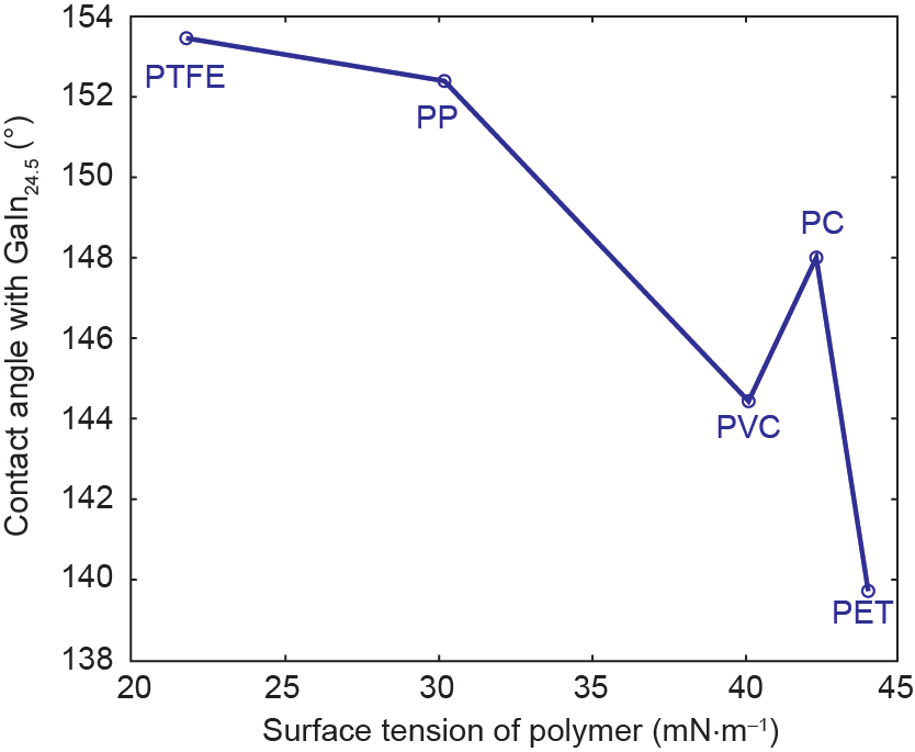
Fig.3 An illustration of the development of printing techniques. (a) Movable-type printing, invented about 1000 years ago; (b) offset printing; (c) screen printing; (d) inkjet printing; (e) laser printing; (f) 3D printing.
The liquid phase of low-melting-point metal at room temperature makes it the natural choice for electronic printing ink, which drives us to explore its great value in the field of printed electronics. As the first effort to print electronics on various flexible substrates, Gao et al. [13] demonstrated a type of brush pen for the direct writing of liquid metal onto substrate materials including glass, cloth, and plastic. The basic function of liquid metal as a flexible electronic printing ink has been verified by the fabrication of a functional circuit. To move forward with the target of printing electronics using liquid metal, Zheng et al. [14] developed a dispenser-like machine to print liquid metal onto coated paper in either two or three dimensions. A small antenna and a large inductance coil have been directly and automatically printed out. However, considering its slow printing speed and low spatial resolution, the desktop printing machine in that study still remains undesirable for personal or pervasive purposes in the field of printed electronics.
Soon afterward, our lab developed the world’s first liquid-metal printer prototype for practical use, first reported in Scientific Reports [3]. To make this machine more practical for personal use, we have made tremendous efforts to design and realize the high-performance and close-to-industrial use machine reported here. We expect this machine to be useful in a wide variety of applications for ordinary end-users in the near future. The liquid-metal printer shown in Figure 4(a) is the most recently developed prototype, and is already close to mass production. This printing system combines the newly disclosed rollerball-pen-like liquid-metal cartridge mechanism with a plotter-like printing principle. Its basic working principle [3] lies in the fact that the liquid-metal ink is pre-loaded and can be uniformly delivered to the tip slot due to the effect of gravity and its adherence to the surface of the roller bead. The ink is then transferred and deposited onto the surface of the substrate. The strong force of the upside-down tapping motion of the printing head and the rolling of the roller bead guarantees an extremely tight adhesion of the ink to the target substrate.
《Fig. 4》
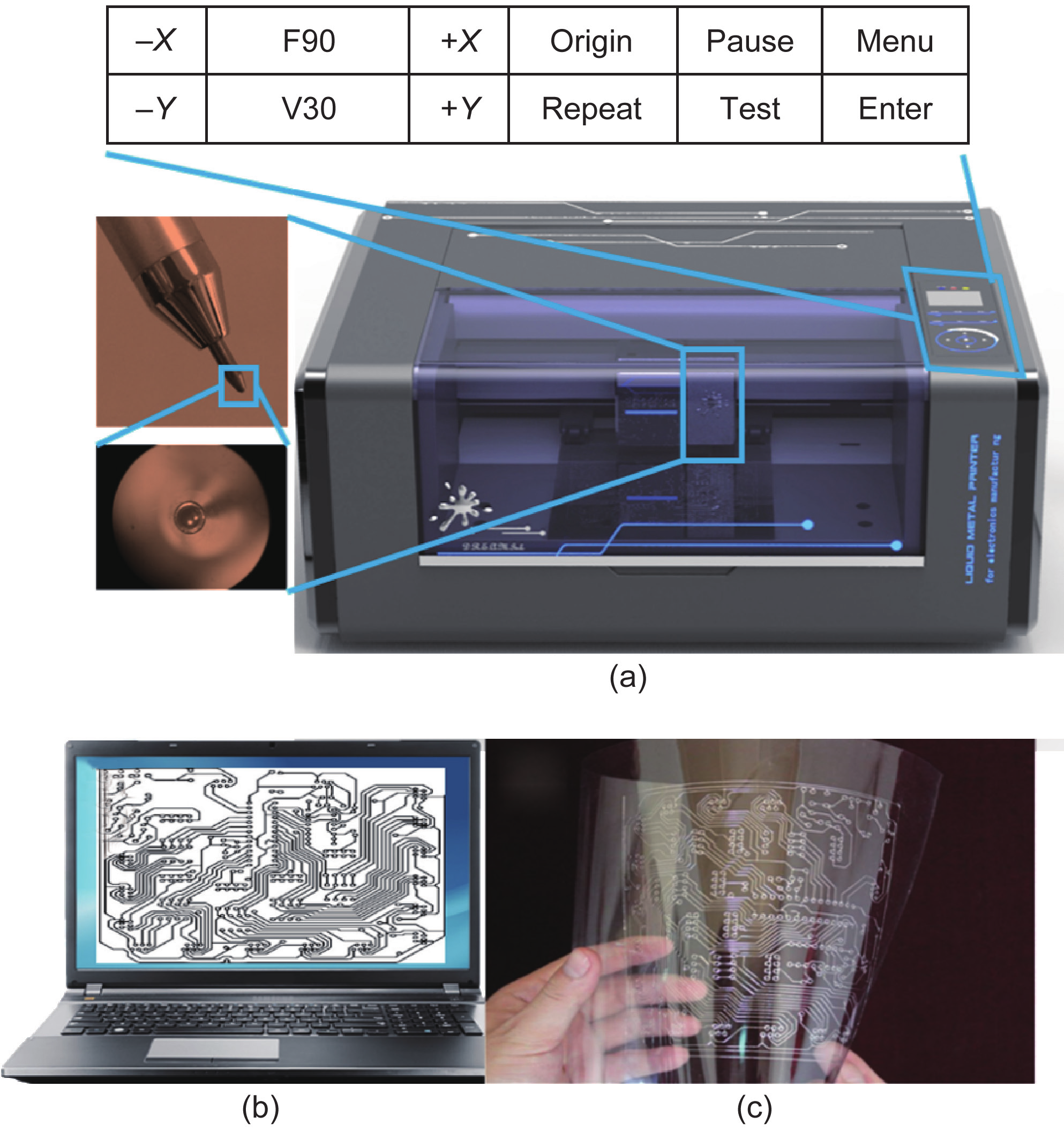
Fig.4 The liquid-metal printer and its printed-out electronic items. Circuits and line drawings can be printed out precisely and quickly by the machine as graphics are transmitted from the control computer via a USB hub. (a) An image of the liquid-metal printer with its rollerball-pen-like liquid-metal cartridge and the parameter-setting interface; (b) the control computer, showing the desired electronic circuit design graphics; (c) circuits that have been directly printed onto a flexible PVC substrate.
Through numerous trials with potential printing substrates, we identified PVC and PET thin films as appropriate printing substrates, taking into account both wettability and cost. In particular, the transparency and flexibility of these substrates make the printed circuits rather attractive. As shown in Figure 2, Young’s contact angle of the liquid metal with PVC is about 144°. While writing with the liquid-metal cartridge, the tiny ball at the point of the pen rolls on the PVC thin film with liquid metal around it, thus pressing liquid metal onto the PVC film. This process makes the liquid metal adhere firmly to the film, and forms writing tracks. In the vertical direction of the tracks, if we apply the description of Young’s contact angle but neglect its condition, the contact angle of the writing tracks with the PVC substrate decreases to 110°, slightly varying with the pressure while writing. Thus, the adhesion between the liquid metal and the PVC film has been improved, making this process the most suitable way to implement liquid-ink printing at the present time. To realize straightforward printing, the liquid-metal printer was developed so that it automatically drives the liquid-metal cartridge to print onto the PVC substrate. A laptop or desktop computer (Figure 4(b)) is required in order to direct the liquid-metal printer to make the desired electronics. A well-developed driver must be installed on the control computer when first connecting it to the liquid-metal printer via a USB hub. From this point on, the liquid-metal printer is easy to use, just like an office printer. The user opens the desired vector graphics (such as the graphics shown in Figure 4(b)) in a processing software (e.g., Microsoft Word), and then just clicks “Print” and chooses the liquid-metal printer. After the printing request has been received, the liquid-metal printer will rapidly print the exact pre-designed patterns onto the substrate film, as shown in Figure 4(c). To achieve this target, the printer drives the liquid-metal cartridge and substrate in two perpendicular directions respective to each other. At the same time, another driver presses down the liquid-metal cartridge to print the electronic patterns, and then holds it up to move to another designated position. In theory, this process allows any pre-designed line patterns to be printed.
The printing parameters of the liquid-metal printer, including printing speed (V30, 120 mm·s−1) and pressure (F90, 282 g), the two crucial parameters for printing performance, can be adjusted via the control panel with an liquid crystal display (LCD) touchscreen. To meet various application circumstances, the printing speed can be adjusted from 0 to 400 mm·s−1 and the pressure can be increased up to 800 g. As discussed in our previous work [3], the width and height of the printed tracks are related to the printing speed and pressure. Operating under excessive speed and insufficient pressure can lead to defects of the printed tracks; based on practical experience, the pressure should be greater than 50 g and the speed should be less than 200 mm·s−1 in order to obtain consistently continuous lines. Pressing “Menu” allows the user to switch to other settings, such as setting the printing start point. The “Test” function will print a small square to verify that all the settings are applicable. Given this complete set of features and controls, a variety of electronic items can be manufactured directly by the user (Figure 4(b) and (c)) under ordinary conditions without additional pre- or post-processing, making the liquid-metal printer an excellent candidate for pervasive use in a wide range of circumstances. Furthermore, the working of printing with a liquid-metal printer is similar to that of printing with an office printer; electrical art or an electric circuit can be printed for a few dollars, which is a reasonable enough cost to permit this technology to have an important impact in the daily life of individuals in the near future. Of course, the methods required to stabilize the electronic circuits, structures, and patterns printed in liquid metal must be considered as an important issue for practical use. To completely ensure the environmental and mechanical stability of such manufactured items, various materials such as polydimethylsiloxane (PDMS) or room-temperature vulcanizing (RTV) silicone rubber can be used to package the products. Readers are referred to our previous paper [3] for more details.
《4. Representative examples of future applications》
4. Representative examples of future applications
Building functional devices via conductive ink printing is becoming increasingly important in a variety of areas [8,15]. Here, in order to show some of the many pervasive uses of the first-ever practical, personal, liquid-metal printer, we chose to illustrate its basic procedure by making an 8 × 8 light-emitting diode (LED) array. First, the schematic for the 8 × 8 LED array (Figure 5(a)) must be determined. There are eight rows and columns of signal leads, making the 64 LEDs independent from each other. For example, in order to light up the LED at row 3 and column 4, the user would connect a positive voltage to row 3 and a ground to column 4 (Figure 5(b)). As shown in the schematic, the row and column leads cross each other, which cannot be avoided while wiring on the same layer. Although the conventional double-layer PCB is a perfect solution for this issue, it is not easy to mimic this solution using liquid-metal tracks, due to their liquid phase at room temperature. We came up with a solution for the crossing of tracks, illustrated in Figure 5(c): The user reserves a gap of about 1.5 mm where a cross occurs, and after the tracks are printed, covers the gap with RTV silicone rubber [3]. The broken track can then be connected manually, after the RTV silicone rubber is vulcanized, using the rubber like an overpass. This approach is suitable for conditions where the crosses are few or are regular, as in the LED array. As the next step in the printing process, the vector format graphics to be applied to the liquid-metal printer should be drawn manually, which can be done with the assistance of a graphic design software such as CorelDraw.
《Fig. 5》
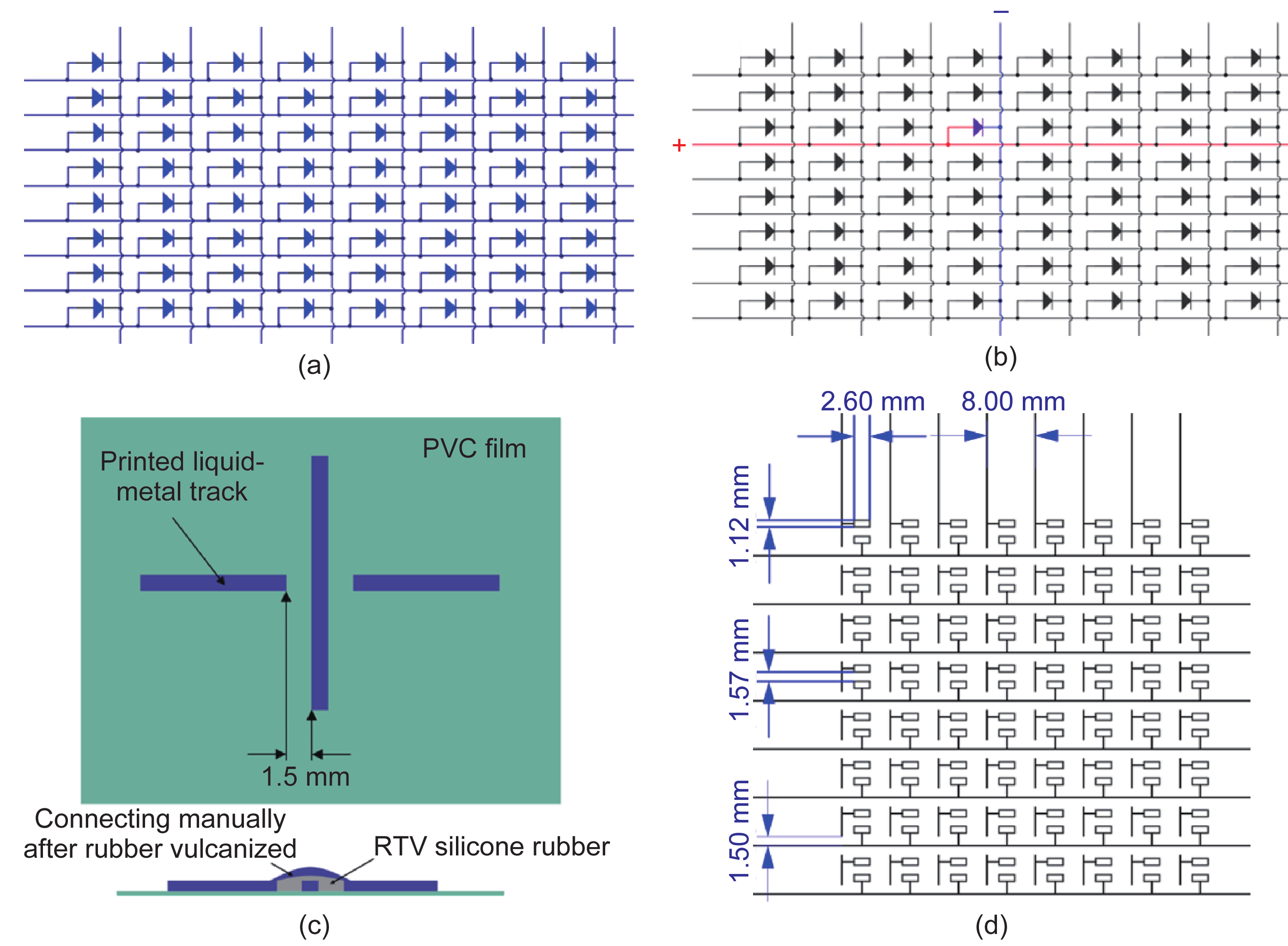
Fig.5 (a) A schematic of an 8 × 8 LED array; (b) an illustration of lighting up the LED at row 3 and column 4; (c) a method of making an overpass-like connection at the crossing of two tracks; (d) an elaborately designed LED array circuit that can be printed with a liquid-metal printer.
For this LED array circuit, the printable graphics (Figure 5(d)) are much like a schematic, aside from the open crosses and the two-pad LEDs. The size of the two-pad LEDs was carefully designed based on real LED packaging, which in this case should be surface-mount packaging instead of in-line packaging, due to the liquid property of the printed tracks. The dimensions provided in Figure 5(d) are suitable for a 1210-packaging surface-mount LED that has an established size according to the industry standard. Of course, the pads of the surface-mount LED are filled rectangles rather than the open rectangles that are represented in Figure 5(d). Since the liquid-metal printer is a kind of line plotter at this stage, only the wire was plotted in the diagram. A filled-in area can be formed when the gaps between two lines are smaller than the spatial resolution of the printer. However, a filled-in area is not compulsory for this LED array application because the printed rectangles can easily be filled in manually. To use the liquid-metal printer to print an LED array circuit (Figure 5(d)), the printable graphics should be in Hewlett-Packard graphics language (HPGL) format, which is the original format supported by the printer.
Once the LED array circuit graphics are fully designed, the user imports them to Microsoft Word and they are ready to be sent to the liquid-metal printer for printing. Within minutes, an LED array circuit can be accurately printed out (Figure 6(a) and (b)). The result is basically the same as shown in Figure 5(d), except that the black lines are now liquid-metal tracks and the substrate is PVC film. Assembling the LEDs simply involves putting the LEDs on the pads and attaching them using tweezers (Figure 6(c)). After all the LEDs are assembled (Figure 6(d)), the broken tracks are connected using the approach described above (Figure 5(c)). This step must be done carefully since the tracks are in a fragile liquid phase. First, a tiny drop of silicone rubber is added to cover the cross areas. Second, the tracks are connected manually using the liquid-metal cartridge after the rubber is vulcanized. Although the LED array is now ready to be verified, coating the whole LED array circuit board with RTV rubber is appropriate and even necessary for long-term use. According to our previous tests [14], there is little variation in the resistance of the printed liquid-metal circuits when they are subject to multiple bending at different angles. This result indicates that well-encapsulated printed arrays can meet the requirements of a flexible circuit satisfactorily.
《Fig. 6》

Fig.6 The procedure of making an LED array. (a) Printing the LED array circuit graphics (Figure 5(d)) automatically, using the liquid-metal printer; (b) the printed LED array, looking almost like graphics; (c) assembling the LEDs with tweezers, ensuring that sufficient electrical conduction is obtained between each LED and the circuit; (d) all LEDs are connected.
The above description presents the full procedure for the completion of an LED array, including designing circuit graphics, printing with the liquid-metal printer, connecting broken tracks, LED assembling, and coating. This procedure largely simplifies the processes of conventional PCB fabrication, which usually include printing, heat transferring, etching and stripping, soldering, and drilling holes, and which depend heavily on expensive facilities. Furthermore, the use of the liquid-metal printer requires fewer materials and instruments than conventional fabrication and avoids risky processes such as chemical etching and high-temperature soldering. The liquid-metal printer is more automated and capable than the fully manual breadboard.
To test the LED array, a microcontroller system was developed to drive lighting patterns. We programmed the system to display numerals and a letter, as well as a heart shape (Figure 7).
《Fig. 7》

Fig.7 A photograph of an LED array displaying “1,” “M,” a heart shape, and “2.” The input pins of the LED array are connected to a microcontroller system with conventional copper leads; the system and leads are not shown in this image. The microcontroller is programmed to display each symbol for one second and then switch to the next symbol in an infinite loop.
The fabrication and verification of an LED array demonstrated our liquid-metal printer to be a practical electronics manufacturing machine that can be used in a wide variety of applications. In addition to making interesting circuits, the printer can be used to create art, for which there is always a demand. Figure 8(a)–(d) exhibits various printed line drawings made of liquid-metal ink, which can be used as a new type of drawing material for the creation of art—one that is distinctly different from graphite-based materials. The liquid metal is highly conductive, providing the possibility of combining artistry with electricity. As a primary effort, we printed the artwork shown in Figure 9(a) and an electronic greeting card shown in Figure 9(b) and decorated them with colorful LEDs. The LEDs make the fabricated paintings quite vivid, a feature that cannot be offered by conventional printed items.
《Fig. 8》

Fig.8 Photographs of printed line drawings made of liquid-metal ink. (a) An eagle with spread wings; (b) a still-life of a bicycle and an umbrella; (c) a copy of the famous Chinese painting Dragon and Phoenix, meaning “goodness and happiness;” (d) a line drawing of the character Bumblebee from the movie Transformers.
《Fig. 9》

Fig.9 Illustrations combining artistry with electricity. (a) A copy of a famous and ancient Chinese painting named " Along the River during the Qingming Festival ; " (b) a Christmas greeting card reading “Merry Christmas.” Both printed liquid-metal paintings have been embedded with colorful LEDs, which makes the art more beautiful and vivid. In particular, the Christmas tree looks like a real Christmas tree decorated with lights.
《5. Discussion and conclusions》
5. Discussion and conclusions
In the primary stage of electrical education, breadboards are usually used when teaching students how to make their own basic functional circuits, because of the breadboards’ usability and flexibility for modification. Teaching students at this stage can now be done using a liquid-metal printer, from which a circuit can be printed out quickly and in a straightforward manner, while simultaneously showing the visualized connections between each electronic component. Furthermore, the liquid-metal ink is reusable after recycling, similar to the reusability of breadboards.
Imagine a situation in which an electronics amateur wants to fabricate PCBs at home. If following the familiar DIY process, the amateur must possess at least a printer, PCB substrates (i.e., flame-retardant #4 or FR4), a laminator, etching materials (e.g., sulfuric acid), and a soldering iron. Alternatively, the amateur can choose to get rid of all these items and potential processes and buy PCBs from a manufacturer, losing the fun of making it for himself or herself. Now the liquid-metal printer offers a brand new way to make PCBs. Only the printer itself, the liquid-metal ink, and the printing substrate are required in order to fabricate the desired circuits, after which the electronics components can be assembled. This new technology thus provides an efficient means of personal electronics manufacturing for the near future. As the liquid-metal printer is capable of printing out any conductive pattern, integration between electronics and artistry could also become a reality. The practical cases illustrated in this article show the capability of the liquid-metal printer for use in electronics manufacturing and in many other circumstances as well, including personal home use; as an educational tool for school, university, or college students; and even as a new art medium for electronic artistry.
After many years of effort in our lab, our new personal liquid-metal printer for pervasive electronics printing is exhibiting a promising future for worldwide use in large-scale application scenarios. Through a comprehensive investigation of the physical properties of liquid metal, the ink-delivering schema, appropriate printing substrates, and automatic-printing processes, we have now designed and fabricated this very practical personal liquid-metal printer. At this stage, the machine is already close to being a customer-level product, with an affordable price and easily obtainable materials, such as PVC film and liquid metal. Clearly, utilization of the liquid-metal printer is much easier than that of most conventional or newly disclosed strategies for printing electronics. Fabricating target electronic products using the printer requires simple procedures composed of a few steps each. These procedures may include: designing printable graphics, printing with the liquid-metal printer, connecting broken tracks if needed, and assembling and coating electronic components. In addition, the liquid-metal printer opens up opportunities for electronics education from elementary school through to university or college. With such basic tools for making electronics at hand, anyone, even a child, can be trained in sophisticated electronics engineering—which is surely an exciting possibility. In our experience, designing complex printable graphics appears to be the most time-consuming part of printing with a liquid-metal printer. However, this part of the process can be partially sped up by sharing graphics applications via the Internet, either for free or through paid downloading. Furthermore, the liquid-metal printer has the intrinsic ability to print artworks, paving the way for artistry that contains electronics as a new element. The liquid metal is even recyclable, due to the liquid phase that remains after coating, making this process more environmentally friendly than many conventional methods.
In summary, our individually-targeted and environmentally friendly liquid-metal printer shows great potential value in a pervasive range of electronics printing applications, including electronics manufacturing, electronics education, artistry, and industrial manufacturing, and will be usable anywhere and at any time in the near future. With such a basic tool becoming a part of daily life, we expect to see the arrival of a wonderful new world in which people can freely make their own electronics to meet their individual needs. Such a tool could stimulate a worldwide explosion of innovation.
《Acknowledgement》
Acknowledgement
This work was partially supported by the Research Funding of the Chinese Academy of Sciences (KGZD-EW-T04-4).
《Compliance with ethics guidelines》
Compliance with ethics guidelines
Jun Yang, Yang Yang, Zhizhu He, Bowei Chen, and Jing Liu declare that they have no conflict of interest or financial conflicts to disclose.


 京公网安备 11010502051620号


