

《1. Introduction》
1. Introduction
Energy drove the industrial revolution in the 1800s, and drives the information technology (IT) revolution of the 21st century. Today, the world’s population stands at over 7 billion. Energy usage per capita in developed countries is too high, with 4.4 t of oil equivalent used per person per annum in the Organisation for Economic Co-operation and Development (OECD) [1]; and developing countries are catching up. The present primary source of energy is fossil fuel in the forms of coal, petroleum, and natural gas. Recent oil price volatility has had a major impact on the energy sector. From mid-2014 to early 2015, the price of oil dropped from over $100 USD to less than $50 USD per barrel, lowering the market prices of natural gas and coal [2]. Although worldwide energy demand is likely to increase, the energy industry cannot continue sourcing energy from fossil fuels over the long term. A revealing statistic is that the total global carbon emissions by the energy sector over the past 27 years is equal to the total for all previous years, with fossil fuels making up more than 80% of the primary energy mix [2]. Greenhouse gas emissions have grown by about half over the past 30 years, with carbon emissions making up almost 60% of the current total greenhouse gas emissions. In 2014, coal, natural gas, and oil contributed about 44%, 20%, and 35% of energy-related carbon dioxide (CO2) emissions, respectively, along with significant quantities of other greenhouse gases including methane and nitrous dioxide [2]. Carbon emissions from the burning of fossil fuels are hastening climate change. According to the National Oceanic and Atmospheric Administration (NOAA) [3], “The first seven months of 2015 comprised the warmest such period on record across the world’s land and ocean surfaces, at 0.85 °C above the 20th century average.” The statistics point toward crisis.
Worldwide, governments have initiated programs of energy production from renewable sources to mitigate anthropogenic-induced climate change, address the possible future exhaustion of fossil fuel supplies, and help ensure national energy security. Energy engineers can make a real difference. Improved energy efficiency is beneficial for both economic and environmental reasons. For example, recent improvements in internal combustion engine efficiency mean that it is possible to raise engine efficiency to almost 60% [4], well above the present peak of 40%. However, further advances must be made in predictive models and engine technology, aimed at higher efficiency and lower emissions, before such engines will roll off car production lines. Engines also need adaptation to use alternative fuels. Carbon capture and storage (CCS) is an alternative near-zero emission technology that involves separating out waste CO2 from power stations and chemical plants, and transferring the CO2 to suitable storage from which it cannot escape to the atmosphere. Although CCS is an expensive technology, it offers the prospect of decarbonizing energy processes in gas-turbine power stations while cutting the global cumulative emission of carbon to the atmosphere [5].
Other ways of limiting carbon, while bridging the energy gap, are to invest in nuclear energy and renewable energy technologies. Although nuclear power appears attractive as a means of producing continuous supplies of clean electricity, there are major concerns regarding radioactive waste disposal, possible accidents (such as the meltdown of three reactors that occurred at Fukushima Nuclear Power Plant in March, 2011) or sabotage, and the proliferation of nuclear arms. According to the International Energy Agency [6], “Renewable energy is derived from natural processes that are replenished constantly. In its various forms, it derives directly from the sun, or from heat generated deep within the earth. Included in the definition is electricity and heat generated from sunlight, wind, oceans, hydropower, biomass, geothermal resources, and biofuels and hydrogen derived from renewable resources.”
《2. Marine renewable energy》
2. Marine renewable energy
Marine renewable energy (MRE) sources include offshore wind, tides, ocean currents, waves, thermal differences, salinity gradients, and biomass [7]. Krewitt et al. [8] estimated the technical potential of offshore wind energy to be ~16 000 (TW·h)·a−1 by 2050. Recently, Capps and Zender [9] computed the global value of offshore wind energy to be ~340 000 (TW·h)·a−1. Although the global total ocean energy resource (excluding wind) has been reckoned to be over 2 million (TW·h)·a−1 [10], estimates as to its technical potential range from about 2000 (TW·h)·a−1 to 92 000 (TW·h)·a−1 [8,11]. Charlier and Justus [12] estimated the theoretical tidal energy potential (including both tidal stream and tidal range) to be 26 000 (TW·h)·a−1, of which about 8800 (TW·h)·a−1 is in shallow coastal basins; though much lower technical potential is anticipated [8,11]. The theoretical wave energy potential is about 32 000 (TW·h)·a−1 [13], with a technical potential of about 5600 (TW·h)·a−1 [8]. The global resource potential of ocean thermal energy conversion (OTEC) is huge, with a theoretical potential of about 44 000 (TW·h)·a−1 [14]. Ocean salinity gradients have an estimated technical potential of about 1650 (TW·h)·a−1 [15].
The global challenge is how to extract the energy, bring it to shore, store it, and export it cost-effectively. Key aspects relate to technology, infrastructure, cost reduction, investment, environmental impact, marine governance, consenting and licensing, and legislation. The marine renewables industry is particularly sensitive to government intervention. To reduce uncertainty, new ocean data-gathering campaigns are vitally needed to provide high-quality information on seabed roughness, wave surface elevations, tidal currents, eddies, and turbulence at sites. The image of Laminaria hyberborea growing on the seabed off Scotland in Fig. 1 indicates just how awkward it is to characterize bed conditions [16,17]. To address barriers to development of MRE systems including device testing at full-scale, grid-connection costs, and a lack of internationally recognized standards for testing MRE technology, various multi-disciplinary MRE technology development roadmaps have been devised (e.g., Refs. [18] and [19]). Small scale tank testing is crucial to initial development and optimization of device concepts (e.g., at IH Cantabria, Spain). Ocean test sites provide scale up to pilot and full prototype conditions, examples being the European Marine Energy Centre (EMEC) in the Orkneys, Scotland (which was established in 2003, is grid connected with 14 berths, and tests wave and tidal devices in water depths 25−50 m); Wave Hub (grid-connected with 4 berths, depths 60−100 m, off Cornwall, England); the one-quarter scale test site in Galway Bay and the full-scale site at Belmullet, Ireland; the three national MRE centers funded by the US Department of Energy: Northwest National Marine Renewable Energy Center (NNMREC) with test sites off the Oregon Coast, in Puget Sound and in Lake Washington, Southwest National Marine Renewable Energy Center (SNMREC) which evaluates ocean current devices in the Florida strait, and the Hawaii National Marine Renewable Energy Center (HINMREC) which tests wave energy converters and components of ocean thermal energy conversion devices. A comprehensive list of present test centers is given by Marine Renewables Canada [20].
《Fig. 1》

Fig.1 Growths of Laminaria hyberborea, found in depths up to 30 m in the Pentland Firth, Scotland [16,17]. The Pentland Firth, a strait between mainland Scotland and the Orkney Isles, is one of the best locations in the world for tidal stream power, with currents that can exceed 5 m•s−1.
The following sections consider different technologies for exploiting marine energy. Detailed review articles include those by Day et al. [21] concerning MRE devices, Khan et al. [22] on marine turbines, Drew et al. [23] on wave energy converters, and Adcock et al. [24] on hydrodynamic models for tidal power assessment.
《2.1. Offshore wind energy》
2.1. Offshore wind energy
Offshore wind-turbine technology has essentially followed that of onshore wind turbines, which evolved from windmills used for electricity production (such as the 12 kW wind turbine constructed by Charles F. Brush in Cleveland, USA, depicted in Fig. 2(a)). Offshore wind turbines typically consist of three blades rotating about a hub, as shown in Fig. 2(b), and are similar to land-based wind turbines. Onshore and offshore wind technology is rapidly evolving, with the largest at the time of writing being SeaTitanTM 10 MW wind turbine of American Superconductor (AMSC) with a hub height of 125 m, rotor diameter of 190 m, rotational speed of 10 r·min−1, blade-tip speed close to 100 m·s−1, and rated power capacity of 10 MW [25]. It appears feasible to upscale individual wind turbines to 20 MW with 250 m rotors [26]. At such high rotor-tip speeds, problems arise from noise and blade erosion. Further research is presently being directed toward offshore floating wind turbines for deep water installation. For example, Principle Power has installed a 2 MW offshore wind turbine on a floating platform off Portugal, with a long-term aim of achieving a future total capacity of 150 MW [27].
《Fig. 2》

Fig.2 Evolution of wind-turbine technology. (a) Charles F. Brush’s electricity-generating windmill, built in 1887−1888 (image courtesy of Wikipedia); (b) a modern offshore wind farm at Thornton Bank in the North Sea off Belgium, comprising 5 MW axial-flow turbines manufactured by Repower (image by Hans Hiller, Wikipedia).
Although offshore wind technology is rapidly being implemented, there remain many fascinating engineering problems to overcome. These include: the design and construction of offshore foundations and floating support structures in the marine environment; alternative turbine designs based on 3D computational fluid dynamics (CFD); the use of advanced materials for rotor blades; more sophisticated and robust control systems, methods of reducing blade-soiling losses, and ship maneuvering for safe maintenance; and shared offshore infrastructure (such as energy production, storage, and marine aquaculture). Fig. 3 presents recent results from a CFD simulation of wind flow past an array of individual turbines representing the Lillgrund wind farm, located off the south coast of Sweden. The results highlight the 3D swirling flow behind the turbines and the wake-turbine interactions from the second row onward.
《Fig. 3》

Fig.3 Computational fluid dynamics (CFD) large-eddy simulation of the Lillgrund wind farm. (Courtesy of Dr. Angus Creech, The University of Edinburgh.)
《2.2. Tidal stream and ocean current energy》
2.2. Tidal stream and ocean current energy
Tidal streams are driven by the head differences across tides as they pass through coastal regions. Tides are produced through tide generating forces arising from the gravitational attraction between water particles in the oceans on the surface of the Earth to the masses of the Moon, Sun, and so on [28]. Tides are complicated by the relative motions of astronomical bodies, Coriolis acceleration owing to the Earth’s rotation, the presence of land masses, and the influence of local seabed topography and roughness [28]. Tides are nevertheless very predictable, a major advantage of tidal energy. Ocean currents are produced by oceanic circulation and wind shear. Tidal and ocean currents often exceed 1 m·s−1, making them candidates for energy exploitation. Exploitable tidal stream resources are concentrated in specific locations such as straits (e.g., the Johnstone Strait, Canada; the Pentland Firth, Scotland; the Sound of Islay, Scotland; and the Cook Strait, New Zealand), off headlands (e.g., the Anglesey Skerries, Wales), in bays (e.g., the Minas Passage in the Bay of Fundy, Canada; and the River Severn, UK), or between islands and landmasses (e.g., Rathlin Island, Ireland) where the coastal geometry helps to enhance the tidal currents. The strongest ocean currents include the northward-directed Florida current which flows into the Gulf Stream travelling from the Carribean to the North Atlantic and the southward-directed Agulhas current which travels along the east coast of South Africa; both currents can reach speeds in the order of 2 m·s−1. There are major differences between ocean and wind power device environments: Ocean flow directions are often more predictable than wind; the sea surface acts to constrain the current and enhance blockage, unlike the atmosphere; seawater is about 800 times denser than air, so energy devices are much more heavily loaded; and the ocean environment is much harsher than that of the atmosphere. Importantly, the presence of tidal or ocean turbines alters the flow field, and this in turn alters power availability. The influence of marine turbines on local flow speeds can persist over large distances [29,30].
To date, few commercial-scale devices have been manufactured and tested, although many innovative tidal and ocean stream energy devices have been proposed (Fig. 4 [31−39]). Such devices may be categorized as follows: axial-flow turbines, cross-flow turbines, oscillating-hydrofoil turbines, and tidal sails and kites.
The axial-flow turbine extracts energy from moving water by means of rotating blades mounted on a rotating hub in much the same way as wind turbines extract energy from moving air. Such turbines may be horizontal-axis or vertical-axis, depending on the mounting. The turbines can comprise bare blades, such as the Atlantis turbine shown in Fig. 4(a); or be ducted (e.g., the Venturi-effect turbine, Fig. 4(b), in which the ducting accelerates the flow as it passes the turbine); or be open-center, with multiple blades surrounding a central hole that promotes jet flow through the aperture, decreasing base pressure, and increasing mass flux (e.g., OpenHydro, Fig. 4(c)). The blades are structural cantilevers, and thus are subjected to very high loads, meaning that the material strength and fatigue characteristics are critically important. As the rotor blades rotate, they sweep out a circle whose area can be used to estimate blockage, a parameter that influences the thrust and hence the available power. The flow field immediately behind the turbine blades has a very strong swirl component.
The cross-flow turbine concept offers exciting prospects. These devices are configured to achieve high flow blockage, and hence maximize power extraction. In this case, the blades are orientated so that the flow passes across the blades, rather like the reverse of a combine harvester. The axis of rotation is perpendicular to the flow direction, and is either horizontal or vertical. The Kepler Energy transverse horizontal axis water turbine (THAWT) device shown in Fig. 4(d) is based on this principle. The Edinburgh vertical axis cross-flow turbine shown in Fig. 4(e) has blades arranged vertically, supported at each end on what are essentially large bicycle wheels. It has variable pitch with rim power take-off, 200 m diameter counter-rotating rotors, a swept area of 10 000 m2, and is believed to be capable of power extraction exceeding 100 MW per rotor [35]. The Gorlov helical turbine (GHT), shown in Fig. 4(f), is essentially a modified Darrieus cross-flow turbine with symmetrical helical blades. The GHT works well in reversing flows.
Oscillating-hydrofoil turbines operate by the lift force acting on a hydrofoil, causing an arm to move, driving fluid in a hydraulic system, and then being converted into electricity. Typical oscillating-hydrofoil devices include Stingray (150 kW); bioSTREAM (150 kW), which mimics fish propulsion, as shown in Fig. 4(g); and the Pulse-System (1.2 MW) concept developed by Pulse Tidal.
Tidal kite turbines, such as that shown in Fig. 4(h), are tethered paravanes that fly underwater, converting the kinetic energy of the current into electricity. By following a figure-eight locus, the tidal kite is potentially very efficient, and operates at currents as low as 1.2 m·s−1 in water depths of 60−120 m. Minesto has tested a kite of 3 m wingspan in Strangford Lough, Northern Ireland, and since designed a kite of 14 m wingspan that should generate 850 kW in a current of 1.7 m·s−1. Minesto has installed a kite of 14 m wingspan in Strangford Lough, Northern Ireland, that can generate 850 kW in a current of 1.7 m·s−1. Minesto intends to develop a 1.5 MW Deep Green array in 2017, and has plans for a 10 MW array in the future.
Various other tidal and ocean current turbines are under development. For example, the Archimedes screw tidal turbine, shown in Fig. 4(i), generates electricity through rotation of the screw by the tidal current. Other examples include the Atlantis Fanbelt Aquanator 400 and Tidal Sails concepts.
《Fig. 4》

Fig.4 Examples of tidal and ocean current devices. (a) Atlantis AK1000 axial-flow turbine (1 MW) [31]; (b) Atlantis Solon-K ducted turbine (1 MW) [32]; (c) OpenHydro open-center turbine (250 kW) [33]; (d) Kepler transverse horizontal axis water turbine (THAWT), a kind of cross-flow turbine (4 MW) [34]; (e) Edinburgh vertical axis cross-flow turbine concept (100 MW) [35]; (f) Gorlov helical turbines before deployment at Cobscook Bay, ME, USA [36]; (g) bioSTREAM (150 kW) oscillatory-hydrofoil turbine (image courtesy of BioPower) [37]; (h) Minesto deep sea tidal kite [38]; (i) Flumill Archimedes screw turbine [39].
Interesting research questions concern uncertainty, turbulence, eddies, wave-current interaction [40], model scale-up, and environmental impact (e.g., on mammals and biodiversity). For example, storm-induced waves can generate water particle velocities that are larger than tidal currents. In addition, wave periods can be of the same order as turbine rotor periods. Turbulence and large-scale eddies affect the uniformity and alignment of the incoming flow, impacting on turbines. Turbulence is only recently being addressed by CFD in the context of tidal and ocean stream turbines at device scale. Recent simulations (Fig. 5) reproduce the swirling turbulent flow behind rotor blades, which forms a wake that interacts with downstream turbines and the local environment. High-performance, big data computing should enable such 3D computational modeling to become routine in future.
《Fig. 5》

Fig.5 CFD model of tidal turbine at device scale. (Courtesy of Dr. Angus Creech, The University of Edinburgh.)
Laboratory-scale models and pilot-scale field tests complement such analysis, providing validation data and insight into the in situ behavior of tidal turbines. Fig. 6(a) [41] shows a scale model of the Oxford THAWT turbine under test in a unidirectional laboratory flume. Fig. 6(b) [42] shows a pilot-scale tidal turbine about to be tested at the European Marine Energy Center (EMEC), located to the north of Orkney, Scotland.
《Fig. 6》

Fig.6 Tidal device testing. (a) A laboratory-scale model of the THAWT device (http://www.keplerenergy.co.uk/) [41]; (b) a pilot-scale model of a 1 MW tidal device at EMEC (image from Atlantis Resources Corporation) [42].
《2.3. Tidal range》
2.3. Tidal range
Tidal range power generation involves the use of enclosures to harness energy in the rise and fall of the tides. Tide mills originated in the early centuries AD, with archaeologists suggesting examples in Roman London and in 6th century Ireland. Modern versions of tide mills are tidal barrages and tidal lagoons. A tidal barrage is a low-head hydropower scheme built across an estuary to form a lagoon. Axial-flow turbines are used to generate power from the head difference due to the tidal range. Table 1 [43,44] lists various installed and proposed tidal barrages around the world.
《Tab.1 》
Tab.1 Tidal barrage sites [43,44].

Power generation by a tidal barrage depends on the instantaneous head. Operational approaches may be categorized as: ① ebb generation (water flowing out of the basin); ② flood generation (water flowing into the basin); ③ two-way generation; and ④ pumping. Although tidal barrages could provide substantial electrical power, they are expensive in terms of capital cost, and the lengthy construction period is a major investment disincentive. Barrage developers must consider navigation and shipping water-level requirements. Environmental issues include concerns about changes to tidal motions in the lagoon, stagnation, loss of water quality, changes to sediment transport, salinity, and biodiversity, and impacts on intertidal periods affecting wading birds. Public and political opposition has hindered the development of tidal barrage schemes to date. A recent review of the state-of-the-art of tidal range technologies is given by Waters and Aggidis [45], who suggest that the lower cost, environmentally less invasive approaches offered by tidal lagoons, reefs, and fences will make tidal range power production more viable in the near future. In the UK, the Severn Estuary has historically been a prime candidate of interest for tidal range power. A previously proposed 16 km long barrage, from Lavernock Point, Cardiff, Wales to Brean Down, Weston−super−Mare, England would have had a total installed capacity of 8640 MW [i.e., 17 (TW·h)·a−1] using 216 bulb turbines each rated at 40 MW [44]. The presently proposed Swansea Bay tidal lagoon could generate total outputs of 320 MW [i.e., 0.63 (TW·h)·a−1] using 16 bidirectional bulb turbines, and has attracted substantial investment [45]. Cost reduction and environmental issues remain the key barriers.
《2.4. Wave energy》
2.4. Wave energy
Many inventions have been devised for wave energy converters (Fig. 7 [46−53]). According to Ref. [7], more than 50 types of device are under development [54−56], including oscillating buoys, floating ducks, snakes, flaps, and enclosed chambers. Here, engineers must find ways to maximize power output, improve efficiency, reduce environmental impact, enhance material robustness and durability, cut capital and recurrent costs, and ensure survivability. Theoretical predictions of the power generated by wave energy converters are being validated through laboratory-scale physical model studies and field tests. Examples of the latest wave laboratory facilities include the circular wave tank, FloWave, at Edinburgh, and the rectangular wave basins at Shanghai, Plymouth, Cork, Trondheim, Ghent, and so forth. Examples of field tests of wave energy converters can be found at WaveHub and EMEC in the UK.
One of the first wave energy devices proposed was Salter’s duck, shown in Fig. 7(a) [46], which undergoes nodding motions in waves and uses the motions to pump hydraulic fluid or to compress air, and thence converts the movement into electricity by means of an internal turbine. At field-scale, Salter’s duck could be arranged in preconfigured patterns in the sea, to exploit the local wave climate. The Pelamis wave energy converter, shown in Fig. 7(b) [47], is made of connected sections that respond to the wave motions by flexing and bending, and hence generate electricity. Developed by the Scottish company Pelamis Wave Power (originally called Ocean Power Delivery), Pelamis became the world’s first offshore wave energy converter to supply electricity into the grid, in 2004. An oscillating water column, shown in Fig. 7(c) [48], uses a large volume of moving water as a piston in a cylinder. Air is forced out of the column as a wave rises and external air is drawn in as the wave falls. The air movement turns a Weir turbine at the top of the column. The Manchester Bobber, shown in Fig. 7(d) [49,50], comprises a rig with semi-submerged floats that move up and down in heave in concert with ocean waves, operating a pulley that spins a fly-wheel connected to an induction electricity generator [50]. At commercial scale, the Manchester Bobber could generate an average of 5 MW, with higher outputs possible in heavy seas. The Manchester Bobber has appeal due to its simplicity, robustness, and ease of maintenance−all electromechanical components are located above the sea surface, with only the bobbers in contact with seawater. In extreme sea states, damage to the rig can be avoided by damping the float motions through the addition of water. The Manchester Bobber floats freely, and thus extracts energy independent of wave direction. The Archimedes wave swing machine, shown in Fig. 7(e) [51], is constructed from a large floating cylinder that is tethered to the seabed, so that it remains at least 6 m below the sea surface. The upper cylinder provides flotation and contains a basement cylinder that generates electricity through repeated up-down motions in harmony with the ocean waves. AWS Ocean Energy installed the first such device off the coast of Orkney in 2007, and has planned a park of 100 AWS machines at a total cost of £250 million. Each device is 13 m in diameter, about 35 m high, 800 t in weight, and can produce up to 1 MW of electricity with a linear generator [51]. The Wave Dragon, shown in Fig. 7(f) [52], traps overtopped ocean waves in a reservoir at an elevation above mean water level, from which electricity is generated by low-head turbines as the water is released back to the sea. The Wave Dragon is a floating wave energy converter, with mooring lines maintaining its approximate position. PowerBuoy, shown in Fig. 7(g) [53], operates as a point absorber, which oscillates up and down in waves, with the mechanical motions being converted into electricity that is either transmitted onshore by means of a submerged cable or immediately utilized if located far offshore. PowerBuoys are manufactured by Ocean Power Technologies (OPT) in Pennington, New Jersey. They are aesthetically non-intrusive, occupy small plan areas, are relatively robust in extreme sea states, and are suitable candidates for OPT farms. Sensors located on the PowerBuoy are used to monitor local conditions, and lock down the device if the wave climate becomes too hostile. PowerBuoys are presently installed or under consideration at nine sites worldwide, particularly off the coasts of Australia and the USA [57].
《Fig. 7》
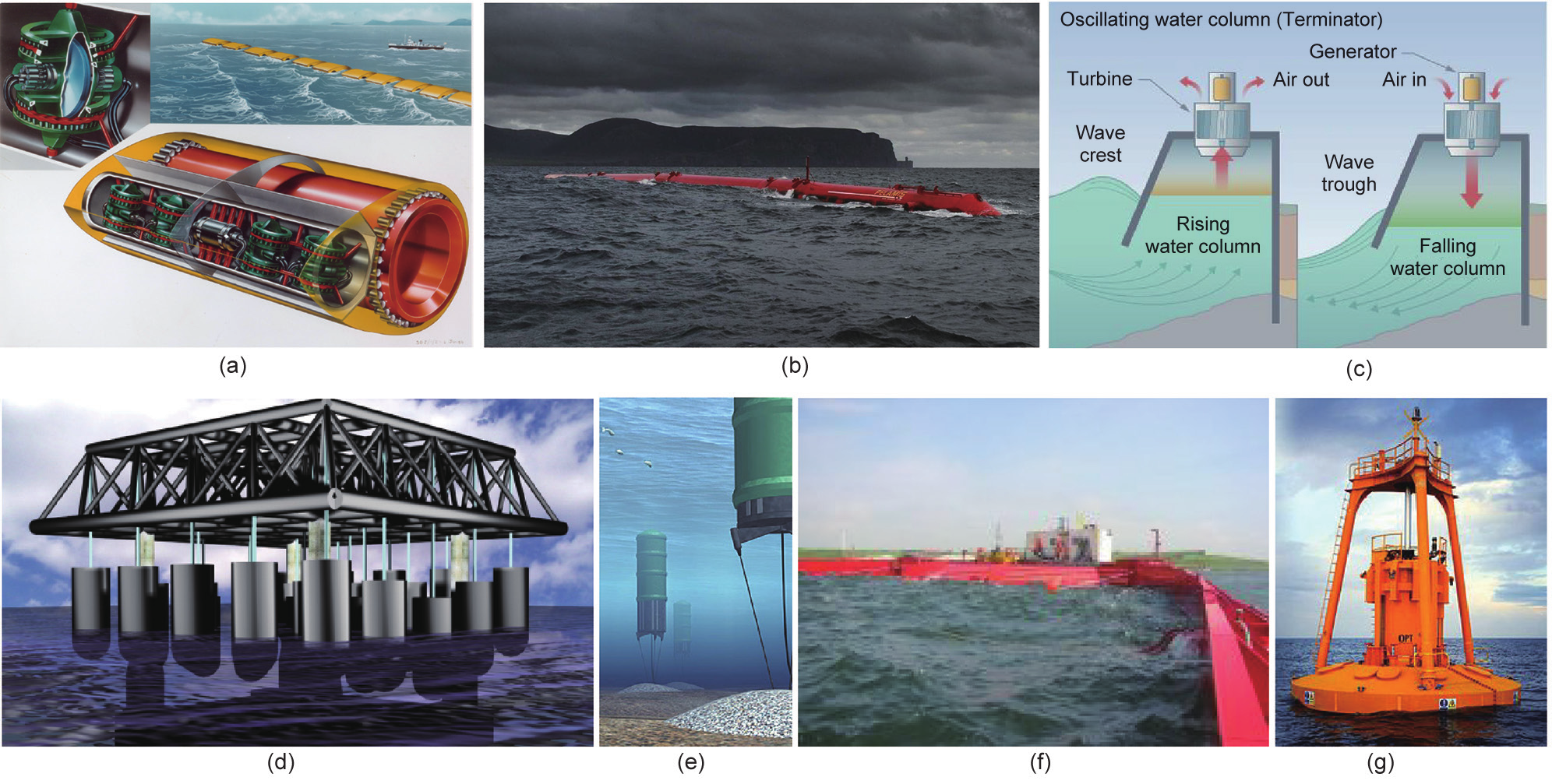
Fig.7 Examples of wave energy converters. (a) Salter’s duck [46]; (b) Pelamis wave energy converter [47]; (c) oscillating water column [48]; (d) Manchester Bobber [49,50]; (e) Archimedes wave swing machine [51]; (f) Wave Dragon [52]; (g) PB150 PowerBuoy with a peak-rated power output of 150 kW [53].
The latest simulation methods involve wave-to-wire modeling of arrays of wave energy converters [58], integrating wave hydrodynamics, body responses, power take-off, real-time control, and electricity production. Such simulations predict time series of wave motions, device response, piston power, accumulated pressure, array power, and output voltage.
《2.5. Ocean thermal energy conversion and salinity gradients》
2.5. Ocean thermal energy conversion and salinity gradients
The oceans act as large stores of thermal energy, absorbing about 15% of solar radiant heat. The ocean thermal energy conversion (OTEC) concept exploits a temperature difference of at least 20 °C between the warm surface layer and cooler depths, and has been proposed for the tropics at depths of the order of 1 km [7,12]. An OTEC plant essentially comprises a heat exchanger with an evaporator and condenser, and proposed technologies operate as closed-cycle, open-cycle, or hybrid-cycle processes [8]. At present, OTEC has proved too costly for field tests, although small-scale closed- and open-cycle plants have been tested in the USA (including Hawaii), Nauru, India, and Japan. Lockheed Martin estimates the commercial cost of a 100 MW OTEC power plant to be about $10 000 USD·kW−1 [59]. Another ocean energy source arises from the chemical potential of salinity gradients where seawater and freshwater meet (e.g., at saline wedges in estuaries). Various technologies have been proposed for salinity-gradient power generation including pressure-retarded osmosis (PRO) [60] and reversed electro-dialysis (RED) [61]. A 5 kW pilot plant producing osmotic power using PRO was installed in 2009 at Tofte, Norway [7], but has since ceased operation because of membrane fouling. In 2014, a pilot-scale RED plant began operation at Afsluitdijk, the Netherlands [62]. Technical issues that still need resolution before RED can be fully implemented include: damage to membranes by natural impurities in water, the filtration of particles, biofouling, the effect of multivalent ions on system performance, the impact on marine species of the substantial pumping process, and the necessity to minimize internal resistance [62].
《2.6. Marine bioenergy》
2.6. Marine bioenergy
Marine algae (such as seaweed) are potential sources of MRE. Marine biomass can be fermented to produce biomethane and/or biohydrogen. Circular economy concepts include: the use of MRE to power aquaculture systems offshore; the growth of seaweed adjacent to fish farms to reduce eutrophication; the harvesting of seaweed on “ripening” at the end of the summer season; the ensiling of seaweed for pre-treatment and year-round provision of feedstock for a biodigester; the reaction of hydrogen generated from surplus MRE with biogas, resulting in the upgrading of biogas to biomethane, almost doubling the methane output (4H2 + CO2 === CH4 + 2H2O); and gas grid injection for use as green gas. In essence, the green gas becomes the energy vector for the distribution of both the MRE and the bioenergy from the seaweed. The energy vector is now readily available for renewable thermal energy, renewable transport energy in natural gas vehicles, and offsite renewable electricity. This use of marine algae offers a resolution to the controversy surrounding the sustainable production of biodiesel and bioethanol from biomass produced on land, where there is competition between food, fuel, and other land uses. Marine algae have very fast growth rates, act as energy reservoirs, and can sequester carbon [63]. Further research and development is necessary to establish the industrial-scale production of algal biofuels [64].
《3. Storage, advanced materials, robotics, and informatics》
3. Storage, advanced materials, robotics, and informatics
Ocean energy output is highly variable. Being created by weather systems, wind and waves are essentially stochastic, seasonal, and subject to inter-annual variability. Tides are cyclic, and comprise multiple oscillating constituents, including semi-diurnal and diurnal components and monthly neap-spring modulations caused by the relative positions of the Sun and Moon with respect to the Earth. The timescales vary from a few hours to many years. Energy storage is therefore essential in order to rectify ocean energy output. Large volume storage options presently under consideration include pumped hydro-storage, hydrogen storage through electrolysis, compressed air energy storage, and substitute natural gas. For example, in the power-to-gas concept, electrolysis is used to generate hydrogen, which is then converted to methane that can be added to the natural gas network (as outlined in Section 2.6) [65−67]. The seascape provides a complex mixture of opportunities in terms of material science, technology, and manufacturing. The ocean climate is particularly harsh and variable; seawater is corrosive; and many different designs have been proposed for marine devices. For example, in axial-flow turbines, the cantilevered rotor blades must be extremely strong to survive in seawater. Novel materials with improved strength, fatigue, and anti-corrosion properties are already on the horizon. Advanced composite materials, such as glass-, carbon-, and basalt-fiber-reinforced polymers [68,69], look to be ideal candidates for cost reduction and increased durability. Fig. 8(a) shows 13 m single-piece wind-turbine blades for 250 kW turbines, produced by ÉireComposites from glass/carbon fiber and powdered epoxy resins using electrically heated ceramic composite tooling, as shown in Fig. 8(b).
《Fig. 8》

Fig.8 Advanced materials for turbine blades. (a) 13 m single-piece wind blades for 250 kW turbines; (b) these are produced from glass/carbon fiber and powdered epoxy resins using electrically heated ceramic composite tooling (photographs courtesy of Prof. Conchúr Ó Brádaigh and ÉireComposites).
Access to MRE facilities is expensive and hazardous. Challenges include remote monitoring, the use of robots for operational support, and real-time weather forecasting for predictive maintenance. All of these are required in order to ensure that devices can survive in extreme sea states as they arise. In addition, of course, MRE informatics systems are the key to improved information management, monitoring, and decision-making. Big data and high-performance computing are also very relevant here.
《4. Perspective on marine renewable energy》
4. Perspective on marine renewable energy
For MRE to be sustainable, it must satisfy economic, environmental, and societal constraints. Impacts should be determined, adverse effects identified, and mitigation measures designed before MRE device deployment takes place. The economic constraint is primarily related to the relative cost of marine electricity with respect to that of other power sources, allowing for capital and recurrent costs, carbon obligations, government subsidies, and market volatility. Marine energy devices can alter flow patterns, introduce noise, and be potential hazards, and they may affect marine biodiversity. Societal acceptance is related to employment prospects, aesthetic concerns, stakeholder involvement, and the wellbeing of communities. Bonar et al. [70] provided a review of the social and ecological impacts of marine power devices.
《4.1. Ethical and legal concerns》
4.1. Ethical and legal concerns
Ethics and legal concerns are important in the context of MRE. The question as to whether marine energy can be owned has philosophical, legal, cultural, and even religious aspects. Another question is, who should own the resource? Is it legally acceptable for one territory to exploit a resource that would otherwise be available to another territory? To answer such questions, a knowledge of ethics and moral philosophy is desirable [71]. Disputes may have to be resolved through the legal process. An example is the dispute between India and Bangladesh that lasted for about 40 years, starting in 1974, and concerned the location of the maritime boundary in the Bay of Bengal. India applied an equidistance principle, whereas Bangladesh applied an equity principle, leading to different, overlapping, and disputed maritime boundaries. The dispute was resolved in 2014 by a United Nations (UN) Arbitration Tribunal.
《4.2. Regulatory environment, governance, and consenting》
4.2. Regulatory environment, governance, and consenting
International ocean governance deals with 60% of the world’s oceans, which lie outside national boundaries and are therefore treated as a shared resource. There is no agreed definition of international ocean governance, and so it is handled legally by means of the UN Convention on the “Law of the Sea” (UNCLOS), which incorporates the rights of various jurisdictions, institutions, and frameworks. The European Union (EU) is presently trying to develop better international ocean governance, and is preparing a European Commission (EC) Communication on Ocean Governance and the Blue Economy. Directive 2014/89/EU [72] explicitly sets out the objective of Integrated Maritime Policy as “to support the sustainable development of seas and oceans and to develop coordinated, coherent and transparent decision-making…whilst achieving good environmental status as set out in Directive 2008/56/EC” and promotes the concept of maritime spatial planning. The EU’s position is based on principles of sustainable development and covers the following key themes: international governance based on the rule of law, the protection of marine biodiversity, climate change, maritime safety, maritime security and freedom of navigation, the promotion of sustainable work in the maritime sectors, and improvement in the current understanding of the sea. To achieve these goals, the EU has imposed environmental legislation governing the sustainable use of marine resources by any entity related to the EU, and has developed regional and European strategies to boost a sustainable blue economy.
Consent is required for all marine locations. However, a multitude of different consenting and licensing processes exist, depending on the scale of the project and the country involved. Consenting is better established for large-scale deployments, but is less consistent for test centers (some of which have preconsenting agreements). Developers claim that regulatory bureaucracy and complicated consenting procedures, including Environmental Impact Assessments, cause delay and act as barriers to the exploitation of MRE [73]. Of the various approaches taken to consenting, the one-stop model appears to be the most effective [73]. In Scotland, developers can seek consent/licenses for marine energy extraction by application to Marine Scotland Licensing Operations Team (MS-LOT). MS-LOT offers a one-stop application procedure, following principles of sustainable marine planning [74]. Game theory [75] could enhance the consenting process, where players are represented by primary stakeholders including developers, energy companies, government, and local communities.
《4.3. Economic constraints》
4.3. Economic constraints
Levelized cost of electricity (LCOE) is defined as the ratio of the sum of the costs over a lifetime to the sum of electrical energy produced over a lifetime. It provides the net present value of the unit cost of electricity over the lifetime of a given electricity source. Table 2 [76,77] lists the LCOE for a range of energy sources determined for the UK in 2010. Meanwhile, Allan et al. [78] estimated in 2011 that onshore wind, offshore wind, tidal stream, and wave energy had LCOE values of £54.4 (MW·h)−1, £81.6 (MW·h)−1, £81.3 (MW·h)−1, and £189.7 (MW·h)−1, whereas CCGT, PWR nuclear, pulverized fuel, and coal with CCS had LCOE values of £34.7 (MW·h)−1, £40.2 (MW·h)−1, £26.2 (MW·h)−1, and £44.8 (MW·h)−1. The various estimates show that cost reduction is essential if MRE is to succeed. Government and private sector support for the MRE industry is critical, but a further barrier to MRE exploitation arises from uncertainty in future subsidies and a lack of private sector investment. Many aspects of the supply chain leading to tidal power require R&D aimed at cost reduction and increased reliability, including advanced materials, manufacturing, installation, power take-off, and energy storage.
《Tab.2》
Tab.2 Estimates of levelized cost of electricity (LCOE) for the UK in 2010 [76,77].

《4.4. Environmental constraints》
4.4. Environmental constraints
MRE development is hampered by a lack of accurate reference environmental data and the propagation of uncertainties through predictive models used to estimate power extraction and its impact on the marine ecosystem. Field data are difficult and expensive to obtain. An improved understanding is needed of the impact of device-device interactions at basin scale, and the long-term ecological side-effects of marine power plants and device farms will not be known until information is available from post-installation monitoring campaigns [70]. MRE devices alter the local flow hydrodynamics, affecting blockage, bypass currents, wakes, mixing, turbulence, sediment transport, littoral drift, scour, turbidity, seabed morphology, biodiversity, food availability, and water quality [70]. Renewable energy device foundations and support structures could act as artificial reefs improving biodiversity, but might attract invasive species. Biofouling may improve species abundance, but can lead to higher sedimentation rates and eutrophication, while antifouling chemicals can be deleterious to certain species. There is concern that certain fish and marine mammals could collide with moving rotor blades, and this danger is exacerbated by poor visibility and locations in zones of high energy [70]. Research is badly needed on marine animal wellbeing under prolonged exposure to noise, electromagnetic radiation, and habitat exclusion.
《4.5. Societal constraints》
4.5. Societal constraints
A “social gap” exists between public support for renewables (due to local employment, cheaper electricity, energy security, and lower carbon emissions) and the lower success of planning applications (due to visual impact; unconcern about climate change; a wish to prevent oceans turning into industrial zones; and damage to tourism, navigation, fisheries, property values, recreation, and social cohesion) [70]. Planning and decision-making processes may cause increased opposition through poor public engagement. This issue is best resolved through improved communication and participation between all stakeholders, though at the cost of a longer, more expensive consultation process.
《4.6. Sustainability assessment》
4.6. Sustainability assessment
In the context of MRE development, sustainability must incorporate economic, societal, environmental, and institutional functions. A sustainability assessment should identify impact generators; set benchmarks and targets; and note the sufficiency of tidal power resources, the accessibility of energy supply and related services, the productive use of energy, resilience to hazards, and equity between different users and generations [79]. Here, sufficiency can be viewed as the capacity of the ocean basin to satisfy its various energy demands (including those of the ecosystem as well as electricity generation). Access relates the availability of the resource to the different stakeholder communities. Productivity concerns the translation of marine power into economically useful electricity. Resilience is a measure of the ocean system’s capacity to mitigate and adapt to changes. Equity refers to the fair distribution of MRE resources between different stakeholders and across generations. Sustainability indicators should be selected systematically, with the aim of creating a logical, well-structured framework for tidal system sustainability assessment. A suitable holistic approach is offered by the process analysis method (PAM) [80], which examines trade-offs between different domains of sustainability, such as economic development, environmental performance, and social wellbeing, allowing for better management and exploitation of MRE resources.
《5. Conclusions》
5. Conclusions
Given the enormous theoretical reserves of ocean energy, the development of new technologies for exploiting MRE appears to be a very worthwhile endeavor for addressing the energy gap, helping to ensure energy security, and reducing global carbon emissions from burning fossil fuels. This article has briefly outlined how MRE can be extracted from offshore wind, tides, ocean currents, and thermal and salinity gradients in the sea, and how bioenergy can be obtained from algae. Worldwide research and development activities are being directed toward tackling the technological, economic, social, and environmental barriers to commercial-scale exploitation of the MRE seascape. Advances are required in cost reduction, energy storage, advanced materials, robotics, informatics, investment, consenting and licensing procedures, and maritime governance. The global challenge remains of how to exploit the MRE seascape in order to power whole cities by ocean energy in a way that is sustainable, robust, and cost-effective. As in the industrial revolution, a new generation of engineers is required that possesses the ingenuity and boldness to meet this global challenge.
In the words of William Shakespeare (taken from the play Julius Caesar, 1599):
There is a tide in the affairs of men,
Which taken at the flood, leads on to fortune.
Omitted, all the voyage of their life is bound in shallows and in miseries.
On such a full sea are we now afloat.
And we must take the current when it serves, or lose our ventures.
《Acknowledgements》
Acknowledgements
The author would like to thank Paul Bonar, Angus Creech, Maggie Creed, Markus Mueller, Mark Linne, Mathieu Lucquiaud, Conchúr Ó Brádaigh, Stephen Salter, Vengatesan Venugopal, Robin Wallace, Harry van der Wiejde (University of Edinburgh, UK), Gillian Bruton, Tony Lewis, Jerry Murphy, Brian Ó Gallachόir (University College Cork, Ireland), Mike Hartnett (NUI Galway, Ireland), Frederic Dias (University College Dublin, Ireland), Dan Toal (University of Limerick, Ireland), John Ringwood (NUI Maynooth, Ireland), Tom Adcock, Guy Houlsby, Sena Serhadlıoğlu, Richard Willden (University of Oxford, UK), and Scott Draper (The University of Western Australia, Australia), all of whom provided useful advice and input into this article. The author is most grateful to the anonymous reviewers for their valuable insights and corrections, which were much to the benefit of this paper. The author is Chairman of the Scientific Advisory Board to the SFI Centre for Marine Renewable Energy Ireland (MaREI).


 京公网安备 11010502051620号


