
《1. Introduction》
1. Introduction
The Three Gorges Project is located at Sandouping in Yichang City, Hubei Province, China. The basin area is about 1 × 10⁶ km2, the average annual flow is 1.43 × 10⁴ m3·s-1, and the average annual runoff is 4.51 × 10¹¹ m3. The main tasks of the Three Gorges Project are flood control, power generation, navigation, and water resource utilization. The normal water level of the reservoir is 175 m, with a corresponding storage of 3.93 × 10¹⁰ m3. The limiting level during flood season is 145 m, with a flood control storage of 2.215 × 10¹⁰ m3. The total installed capacity is 2.25 × 10⁴ MW, and the annual average generating output is 8.82 × 10¹⁰ kW·h.
The overall layout of the project is as follows [1]: Flood discharge dam sections are located in the middle of the riverbed, while left- and right-bank plant sections and non-overflow sections are located on both sides. The powerhouses are arranged on the downstream side of the plant sections, while the navigation structure lies on the left bank. The Maoping Creek protection dam lies on the export of Maoping Creek on the upstream right bank. The underground powerhouse is in Baiyanjian Mountain, on the right bank. Fig. 1 shows the layout of the Three Gorges Project. The dam type is a concrete gravity dam with a total axis length of 2309.5 m. The dam crest elevation is 185 m and the dam's maximum height is 181 m. The generation structures consist of a dam toe powerhouse, an underground powerhouse, and a power source station, which install a total of 32 units generating 700 MW each and two units generating 50 MW each. The navigation structures consist of a ship lock and a vertical ship lift. The ship lock is a continual five-step ship lock in a double line, with a one-way annual transport ability of 5 × 10⁷ t. The maximum lifting height of the ship lift is 113 m and the maximum carrying scale is 3000 t.
The Three Gorges Project maintains a world-leading position in many areas such as engineering scale, comprehensive utilization benefits, and technological level. Its design difficulty is beyond that of any existing water conservancy and hydropower project in the world. There are a series of challenging key technological problems in the design process of hydraulic structures such as this one [2]. The gravity dam, the powerhouse at the dam toe, the underground powerhouse, and the five-step ship lock are illustrated in this paper in order to show the key technology and practice in the design of the Three Gorges Project.
《Fig. 1》

Fig.1 Layout of the Three Gorges Project.
《2. Key technology of gravity dam design》
2. Key technology of gravity dam design
《2.1. Flood discharge and energy dissipation technology with high water head and super-large discharge》
2.1. Flood discharge and energy dissipation technology with high water head and super-large discharge
The designed flood discharge amount of the Three Gorges Project dam is 9.88 × 10⁴ m3·s-1, while the check amount is 1.243 × 10⁵ m3·s-1. The third-stage river closure designed discharge is 1.03 × 10⁴ m3·s-1, the designed flood discharge is 7.23 × 10⁴ m3·s-1, and the check amount is 8.37 × 10⁴ m3·s-1 in the period of power generation with the third-stage cofferdam retaining water. Thus, the flood discharge structure of the Three Gorges Project has the characteristics of a large flood discharge, a high water head, a multi-objective task, and so forth. Due to the large installed capacity, and hence the large number of installed units, the flood discharge dam section is required to be as short as possible [3]. After years of research, through optimizing and adjusting the flow path shape and structure and the arrangement of gate and related facilities, a layout of staggered three-layer large discharge orifices was successfully implemented [4]. The leading edge length of the flood discharge dam section was ultimately determined to be 483 m, divided into 23 monoliths. One of the 23 deep outlets, which are 7 m × 9 m in size, is arranged in the middle of each dam section, and the bottom elevation of the inlet is 90 m. One of the 22 crest outlets is arranged across each transverse joint, with a weir crest elevation of 158 m and a width of 8 m. Just below the crest outlets and across the transverse joints, 22 bottom outlets sized 6 m × 8.5 m are arranged. The bottom elevation of the inlet is 56 m or 57 m. Fig. 2 shows the layout of the three-layer orifices. Not only does this innovative layout meet the multi-objective operation requirements of third-stage river closure, flood discharge in the period of power generation with the cofferdam retaining water, water and sand discharge during the operating period, and water-level lowering when necessary; it also shortens the length of the flood discharge dam section greatly, reduces the excavation on both abutments, and saves on the engineering investment.
The most important characteristics of the deep outlet are its long operation time, high discharge velocity, and serious cavitation and erosion of the flow-passing surface. Therefore, the short pressure tube scheme versus the long pressure tube scheme, as well as the inclined chute versus aeration with vertical drop or with sudden enlargement for the open-flow chute section, were compared comprehensively, and the short pressure tube with vertical drop aeration was finally adopted [5]. Due to the large amplitude variation of the water level and the short open-flow chute, the design of this scheme is difficult; not only does it have to ensure a stable cavity being formed under the condition of a low water level, but it also has to avoid the water flow jetting into the ogee section directly during a high water level. Through a series of experimental studies, an aeration drop bucket was arranged at the first longitudinal joint, about 11 m away from the outlet of the pressure tube. A combination of a 1.5 m high vertical drop and a 1:4 slope after the sill was adopted. This technology provides an important guarantee for the long-term safe operation of the deep outlets.
The most important characteristics of the diversion bottom outlet are the joint-crossing arrangement and the large amount of sediment passing through the outlet; thus, sediment abrasion and cavitation erosion of the flow-passing surface is a significant problem. Through a great deal of scientific research, comprehensive measures were determined to solve these problems. Firstly, a long pressure tube with a suitably large size was adopted to reduce the flow velocity in the outlets. Secondly, an anti-scouring concrete slab was set up across the joint in order to avoid the adverse effects of the outlet joint and to enhance the anti-abrasion ability of the flow-passing surface. Finally, a sediment-retaining slot was set up at the entrance in order to reduce sediment across the outlets [6].
The discharge structures of the Three Gorges Project have the features of large flood discharge, high water head, and huge discharge power. Based on the layout with staggered three-layer large discharge orifices, combined with the actual situation of a downstream energy dissipation zone, ski-jump energy dissipation with a largely differential flip bucket was used for crest outlets and deep outlets. The drop points of the water tongues are staggered in a longitudinal direction, and the scour depth is greatly reduced. The water level variation of the bottom outlet is about 70 m, and a submerged bucket dissipater is adopted. An optimal combination of different inlet elevations and bucket shapes was adopted for the 22 diversion bottom outlets, and partition piers were set at the right side of the energy dissipation zone. A good flow pattern and energy dissipation effect are obtained under all operational conditions, and the downstream scour and deposition patterns are effectively controlled.
《Fig. 2》
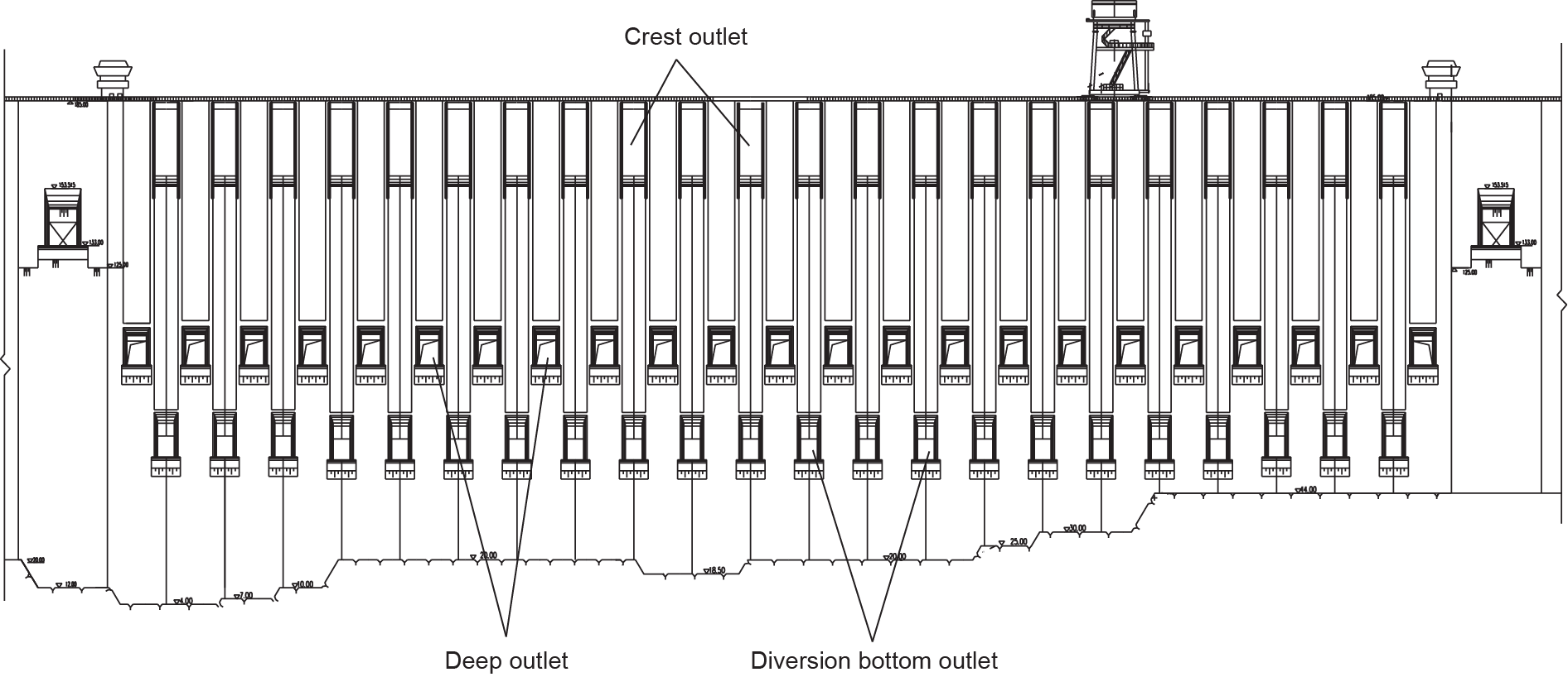
Fig.2 Layout of the three-layer orifices.
The discharge structures have been in operation for more than 10 years, and withstood a maximum inbound peak flow of 7.12 × 10⁴ m3·s-1 in 2012 (a nearly 5% frequency flood).
The hydraulic monitoring and inspection results of the deep outlets show that, when the reservoir reaches a water level of 172.6 m, the water surface is smooth in the entrance of the outlets and the high-frequency noise spectrum is smaller than 5 dB, indicating that there is no obvious cavitation phenomenon. The drop downstream of the discharge chute of the deep outlet has a stable bottom cavity with a negative pressure of −0.5 × 9.81 kPa, and the minimum aeration density reaches 2.2% in the bottom water flow, which satisfies the requirement for cavitation alleviation. Erosion and deposition data of the energy dissipation area that was measured in 2002 shows that the minimum elevation of the scouring pit in the middle riverbed is 23.5 m, which can be converted to a gradient of 1:5 from the dam toe to the scouring pit; on the two sides of the energy dissipation area, the elevations of the scouring pit are all higher than that of the base of the guide wall. Therefore, the operation of the flood discharge facility is safe.
《2.2. Design method of large orifice structure》
2.2. Design method of large orifice structure
As shown in Fig. 3, three-layer large discharge orifices consisting of a crest outlet, a deep outlet, and a diversion bottom outlet are arranged in each monolith of the flood discharge dam section in the Three Gorges Project. The characteristics of the high dam opening rate (31% in plane, 32% in facade, and 31% in volume), large orifice size, high water head (the design head of the deep outlet is 85 m), frequent operation, greatly varied water level, and complex structure are unprecedented in the world. During the structural design of this multi-layer large orifice gravity dam, research on reinforced concrete nonlinear finite element crack analysis and the nonlinear reinforcement design method were first carried out in China. The relationship between the orifice reinforcement and crack properties was systematically analyzed and, based on the results, effective and comprehensive measures for reducing the orifice stress and crack width were presented.
《Fig. 3》

Fig.3 Three-dimensional diagram of the three-layer orifices.
The tensile stress graphical method is usually used in traditional orifice reinforcement design; however, the orifice crack distribution and width cannot be obtained by this method. As the main purpose of reinforcing bars is to limit the crack width and to ensure the structure's bearing capacity, using only the tensile stress graphical method for reinforcement design is insufficient for large orifice structures such as the deep outlets of the Three Gorges Dam, given the high water pressure, thin peripheral structure, and poor stress state. Therefore, the reinforced concrete nonlinear finite element method was introduced for orifice crack analysis. In this method, an orthogonal anisotropic nonlinear model is adopted for the constitutive relationship of concrete. The decline segment of the tensile stress-strain curve is not considered, and the compressive modulus of elasticity is calculated according to Eq. (1) [7]:

where, σi is the principal stress in direction i; εiu is the equivalent uniaxial strain; εic is the equivalent uniaxial strain corresponding to the maximum stress σic; E0 is the tangent elasticity modulus at the origin point; Es is the secant modulus corresponding to maximum stress σic, and Es = σic/ εic.
A smeared crack model was used to simulate the concrete crack. When the principal tensile stress becomes greater than the tensile strength of the concrete under an incremental load, a crack will occur in this direction and the concrete elastic modulus is set to zero. It was previously thought that the crack width could not be obtained by nonlinear analysis based on the smeared crack model. However, through the adoption of “maximum tensile stress cracking element criteria” and by improving the nonlinear iterative process [8], the actual crack width can in fact be obtained. The constitutive relation of a hardening elastoplastic model was adopted for the steel bars, and a double spring element was used to simulate the bond-slip between the reinforced steel bar and concrete in the nonlinear analysis of the Three Gorges Dam.
According to the calculated results, the tensile stress of the pressure segment of the deep outlet ranges from 2 MPa to 3 MPa, and the maximum depth of the tensile area is 8.5 m. The crack width cannot meet the requirements, even with four to five layers of steel bars with 40 mm diameter. Based on the formation mechanism of the tensile stress in the orifices, innovation measures were put forward to decrease the orifice stress. One measure was to move the water stop in the dam's transverse joints downstream in order to utilize the outside water pressure in the joint to balance the inner water pressure of the orifice; another measure was to raise the dam's transverse joint grouting elevation in order to increase the lateral stiffness to reduce the stress of the orifice [9]. After adopting these measures, the tensile stress of the pressure segment of the deep outlets was significantly reduced, and only three rows of steel bars around the orifice were generally needed to meet crack-controlling requirements with a maximum crack width of 0.2 mm.
Fifty-two reinforcement stress detectors were arranged around the deep outlet of the No.2 discharge dam monolith which is the highest dam section. The operation monitoring results show that the tensile stress of the steel bars in each location around the deep outlets is small, and that the monitoring data is mainly affected by the water level and is stable overall. The nonlinear reinforcement design method of multi-layer large orifice structures, used in the Three Gorges Dam, has been successfully put into application. In this method, the crack width is calculated by the reinforced concrete nonlinear finite element and meets the design requirements through an adjustment of the reinforcement arrangement and amount, based on the results calculated by the tensile stress graphical method. This nonlinear reinforcement design method has been adopted by the Design code for hydraulic concrete structures (SL 191-2008) [10].
《3. Key technology of powerhouse design》
3. Key technology of powerhouse design
《3.1. Structure design technology of shallowly buried reinforced concrete penstock with steel lining in powerhouse at dam toe》
3.1. Structure design technology of shallowly buried reinforced concrete penstock with steel lining in powerhouse at dam toe
The headrace pipe type of powerhouse located at the dam toe of the Three Gorges Project is one unit with one pipe. The maximum discharge is 966.4 m3·s−1 and the diameter of the penstock is 12.4 m. The design head is 139.5 m and the HD2 value (“H” means the water head, and “D” means the diameter of headrace pipe) is 21 450 m2—the greatest in the world [11]. One of the key technology problems of the powerhouse at the dam toe is how to choose the structure type of the penstock, so as to create a good headrace condition and ensure that the dam and penstock are safe.
As the diameter of the penstock of the Three Gorges Project powerhouse at the dam toe is so large, there are several problems if the pipe is wholly arranged in the dam body, such as weakening of the dam structure, disturbance in the construction process, and a long construction period. On the other hand, if the total pipe is arranged on the downstream surface of the gravity dam, there are lateral stability problems, especially anti-seismic stability problems for a penstock with high HD values; therefore, it is difficult to make the structure safe. A new type of penstock named “shallowly buried reinforced concrete penstock with steel lining at the dam toe” (shallowly buried pipe at the dam toe for short) was proposed. In this penstock, a shallow slot is preset on the downstream surface of the gravity dam, and a third of the pipe diameter is buried in the slot. Steel lining and reinforced concrete bear the water load together, as shown in Fig. 4.
《Fig. 4》

Fig.4 Schema of preset shallow slot for headrace penstock and reinforced concrete pipe with steel lining (unit: m).
A series of numerical analyses, a large-ratio (1:2) simulated structural model test, several small-ratio simulated structural model tests, and a structural integrated anti-seismic test were conducted for the shallowly buried penstock at the dam toe in the Three Gorges Project. Based on a full understanding of the joint load-carrying mechanism between the reinforced concrete and the steel lining, a joint load-carrying structural design method called the “equal safety degree method” for a shallowly buried penstock at the dam toe was proposed. In this theory, the steel lining and the encircling concrete are considered as a composite structure, carrying the load jointly. The design standard is that the total safety factor of this composite structure will be no smaller than 2.0, and the steel strength usage ratios of the steel lining and the encircling reinforced concrete will be nearly the same. The steel plate depth and reinforcement can be calculated according to Eq. (2). Furthermore, the crack width of the encircling concrete should be controlled at less than 0.3 mm in the serviceability limit state.

where, K is the total safety factor of the composite structure; P and r are the designed internal water pressure (N·mm−2) and steel pipe diameter (mm), respectively; t and t3 are the thickness of the steel pipe and the converted thickness of the reinforcement (mm), respectively; σs and fyk are the yield strength of the steel plate and the tensile strength of the reinforcement (N·mm−2), respectively; and φ is the weld coefficient.
The left powerhouse at the dam toe of the Three Gorges Project has been running for 14 years. The monitoring data for the shallowly buried penstock from 2008 to 2013 shows that the stress laws of the steel lining and reinforcement in the top, side, and bottom of the penstock remain consistent with the design analysis. Specifically, when the reservoir reaches its normal water level of 175 m, the maximum stress is 118 MPa and 93 MPa for the reinforcement and steel lining in the skew part of the penstock, or about 63% and 46% of the allowable stress, respectively; no crack was found in the concrete of the penstock's upper curved part, and the crack width of the concrete in the skew part is smaller than 0.3 mm. Therefore, the penstock in the powerhouse at the dam toe is operating well and the design code for the penstock has been modified according to the design method and operating practices of the Three Gorges Project. The equations proposed above have been adopted in the Design specifications for steel penstocks of hydroelectric stations (SL 281-2003) [12].
《3.2. Design technology of tailrace tunnel with sloping ceiling for underground powerhouse》
3.2. Design technology of tailrace tunnel with sloping ceiling for underground powerhouse
The maximum discharge of a single unit of the underground powerhouse in the Three Gorges Project is 991.8 m3·s-1, and the rated water head is 85 m. According to the traditional design method, a tailrace surge chamber with a large scale should be set in this place. In this case, the surrounding rock stability problem of caverns caused by a high excavation vacuum rate is very significant because the Baiyanjian Mountain, where the underground powerhouse is located, is thin with developed rock blocks.
Therefore, by deeply studying the relationship of the turbine installation elevation, tailrace length under pressure, and downstream water level using methods of theory analysis, numerical simulation, and model testing, a new tailrace tunnel type with free and pressure flow mixing together, named a “tailrace tunnel with sloping ceiling” was proposed, breaking through the traditional design type of a tailrace tunnel with pressure or not; and the corresponding design theory and method were built. The working principle of the new tailrace tunnel is to use the relationship of the downstream water level variation and the length of the pressure flow section of the tailrace tunnel with an inclined roof in order to automatically satisfy the vacuum degree of the tailrace inlet requirements in the case of different submerge depths of the turbine in the load rejection transient process. As shown in Fig. 5, when the downstream water level is low, the submerge depth of the turbine is small; then, the free flow section is long while the pressure flow section is short. In this situation, the negative water hammer pressure is small in the transient process, and the vacuum degree of the tailrace tunnel inlet meets the design code requirement. As the downstream water level rises, the length of the free flow section gradually shortens, and that of the pressure flow section increases. In this situation, the negative hammer pressure becomes bigger and bigger, but the turbine submerge increases gradually as well. Thus, the positive and negative aspects counteract to keep the vacuum degree of the tailrace inlet under control in order to satisfy the code requirement, indicating that the tailrace tunnel plays the role of a tailrace surge chamber. Since a tailrace surge chamber becomes unnecessary when adopting a tailrace tunnel with a sloping ceiling, the layout of the underground caverns can be simplified and the surrounding rock stability can be improved [13].
When designing the shape of a tailrace tunnel with a sloping ceiling, according to the lowest tail water level, the maximum length of the pressure flow section is determined first. This will be the starting point of the sloping ceiling. Next, the floor elevation and the width of the tailrace tunnel outlet are determined, according to the different tail water levels, outlet water flow speed, and topographical and geological conditions. The top ele-vation of the tailrace tunnel outlet and the curve of the tailrace tunnel ceiling surface are chosen last. In the formulation of this surface curve, the rigid water hammer equation can be used for calculating water hammer pressure. Assuming that the extreme value of the water hammer pressure and of the transient wave height happen at the same time, by integrating Eq. (3), the relationship of the length of pressure flow section Land the interface section area F(L), or the relationship between Land the tunnel's top elevation Z, can be obtained [14]. The top surface curve of the tailrace tunnel is parabolic according to this equation, but the vast majority of these curves are designed as a straight line in practice for more convenient construction. A diagonal straight line that is slightly lower than or equal to the top slope is adopted at the bottom of the tunnel to shorten the height of the tunnel.
《Fig. 5》

Fig.5 Schema of tailrace tunnel with sloping ceiling.

where, q is the ratio of the turbine flow Q(t)and the base flow Q0; ( H2 + ΔZ) is the superposition of the downstream submerge water depth and the water fluctuations of the free flow section; and L and F( L) are the length of the pressure flow section and the area of the interface section, respectively.
Fig. 6 shows the design shape of the tailrace tunnel with sloping ceiling in the Three Gorges Project. For this design scheme, a large-scale experimental study with water, machinery, and electricity united in the transition process was conducted for the first time in China. The various operating conditions of large fluctuation, tiny fluctuation, and hydraulic disturbance tests were carried out, and the unit transition process parameter values were proposed in quantity. Specifically, the maximum pressure rise in the volute inlet is 149 mH2O≤ 160 mH2O, 1 mH2O = 9806.65 Pa), the maximum unit rotation rise is 50.7% ≤ 55%), and the maximum vacuum degree of the draft tube is 5.5 mH2O≤ 8 mH2O). Under the minimum water head, the variation amplitude of frequency is smaller than 4.2% and becomes stable in half of an oscillation period, when the step change of the load is 5%. The variation amplitude of frequency is smaller than 8% and becomes stable in an oscillation period when the unit has 10% load rejection with 90% full power. The influence of the hydraulic characteristics of a tailrace tunnel with sloping ceiling on the stability of the unit is correctly reflected, and the hydraulic characteristics in steady flow and unsteady flow conditions are revealed [15]. When using a tailrace tunnel with sloping ceiling technology, the vertical surge shaft shape is replaced with a horizontal one. Both types of shafts have the surge wave reflection from free surfaces in common, but the water fluctuation of the former is a mass wave, while the fluctuation of the latter is a gravitational wave. An innovation of a way of regulating tail water was implemented.
《3.3. Stable arch design method for the surrounding rock of shallowly buried super-large underground caverns》
3.3. Stable arch design method for the surrounding rock of shallowly buried super-large underground caverns
Being restricted by the project layout and the geological and topographical conditions, the underground powerhouse of the Three Gorges Project is arranged inside the Baiyanjian Mountain on the right bank, with the minimum thickness of the rock mass over the powerhouse being less than the powerhouse span. Obviously, this cannot meet the current code's requirement for an underground powerhouse, so the top arch stability is a key technological problem in the underground powerhouse design. For such a shallowly buried underground cavern, with a large span and a high sidewall, no mature theory and method exist to execute the cavern arch design. Based on systematic research into stable arch-forming conditions and the bearing mechanism, as well as into the main controlling aspects and influence laws of the surrounding rock stability of large underground caverns, a methodology for the stable arch design of a shallowly buried super-large underground cavern was proposed and was successfully applied to the Three Gorges Project's underground powerhouse [16].
From a basis of traditional arch theory, the arch effect and the stability of the rock mass of shallowly buried underground caverns were further studied. The bearing mechanism of the surrounding rock at the top arch area was discovered: ① The principal compressive stress area with the arch effect is formed within a certain range of the cavern's top arch in order to support and transfer the unbalanced load due to the rock excavation; and ② when the overburden depth is not enough, the principal compressive stress contour of the surrounding rock arch is not closed, causing the arch effect to disappear and the top arch to be instable and then collapse, and resulting in the appearance of uplift damage.
A stable arch in the surrounding rock mass acts as a kind of bearing arch, simultaneously satisfying the requirements of structural stability and material strength. Its formation requires two mechanical conditions [16]: ① a structural stability condition—that is, a closed contour of the principal compressive stress zone is formed in the top arch of the rock mass, which means that a stable support can be provided by the abutment rock mass; and ② a material strength condition-that is, the compressive and shear strength controlling standards are satisfied at the same time (Eq. (4)). A stable arch can be determined according to the principal stress direction change characteristics in the secondary stress field of the surrounding rock, as shown in Fig. 7.

where, σ is the principal compressive stress of the surrounding rock in the arch area; Kν is the rock integrity factor; Rc is the saturated uniaxial compressive strength of the rock; and cm and φm are the cohesive force and the internal friction angle, respectively.
The thickness of the overburden rock mass of the underground cavern has an important influence on the stability of the top arch in the surrounding rock, and is directly related to the formation of the surrounding rock stable arch. As shown in Fig. 8, under certain conditions of the geological environment and of horizontal stress, the cavern's buried depth is closely related to the formation of a stable arch, and a minimum depth exists. Through research on the influence of the features of different buried depths on the surrounding rock mass stable arch, criteria for the minimum thickness of the overburden rock mass above the top arch were established, according to whether a stable arch ring of principal compressive stress can be formed in the top arch of the surrounding rock or not. Based on these criteria, a design method for a stable arch of surrounding rock in a shallowly buried super-large underground cavern was put forward.
《Fig. 6》
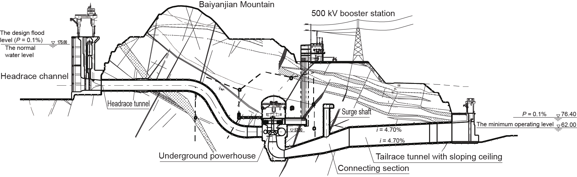
Fig.6 Longitudinal section of waterway system of the Three Gorges Project's underground powerhouse.
《Fig. 7》

Fig.7 Determining the method for a stable arch shape of the surrounding rock.
This method was applied in the design and construction of the underground powerhouse of the Three Gorges Project. The limitation of the Design code for hydropower housethat “the overburden thickness of a cavern should not be less than two times the cavern span” was broken, and a large, shallowly buried underground powerhouse was successfully built. This underground powerhouse's excavation dimension is the largest in the world, and its buried depth is less than its span.
Operational observations over several years show that the maximum deformation of the top arch area of the underground powerhouse is 2.2 mm, while the maximum deformation of the arch abutment is 8.1 mm; the maximum stress is smaller than 150 MPa for the anchors in the surrounding rock. The deformation of the surrounding rock has become convergent, and the stress of the anchors has been stable since 2008. This stability indicates that, under the given rock mass strength, rock mass structure, and initial geo-stress conditions, the above-mentioned surrounding rock stable arch design methodology for a shallowly buried super-large underground cavern is appropriate and reliable for the design of the underground powerhouse of the Three Gorges Project, and that the surrounding rock stability and project safety can be both satisfied. The design theory and method used to solve the surrounding rock stability problems in the design of a shallowly buried super-large underground cavern are therefore provided here as a reliable and tested methodology.
《4. Key technology of five-step ship lock design》
4. Key technology of five-step ship lock design
《4.1. Water-conveyance technology with high water head and large water flow》
4.1. Water-conveyance technology with high water head and large water flow
The double-line continuous five-step ship lock of the Three Gorges Project is the largest inland ship lock with the largest scale, highest operating water head of the valves, and most complicated technology in the world [17]. The designed total water head is 113 m and the maximum operating head of the valves is 45.2 m. The one-way carrying capacity is designed as 5 × 10⁷ t, and the navigation clearance is 18 m. The effective dimensions of its lock chamber are 280 m × 34 m × 5 m (length × width × minimum water depth above sill). The total length of the lock line is 6442 m.
《Fig. 8》
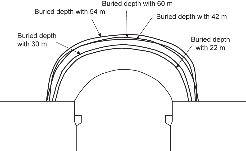
Fig.8 Shape plot of the stable arch of the main powerhouse cavern under different buried depths.
The designed water-conveyance time of the Three Gorges ship lock is 12 min and the volume reaches 2.37 × 10⁵ m3 each time. Its comprehensive hydraulic index ranks at the highest level in the world, and requires an extremely harsh performance from the water-filling and water-emptying system. The key technology in the hydraulic design addresses the issue of how to guarantee the operational safety of the culvert and valve gears, and the chamber parking condition in the required water-conveyance time [18,19]. The type of water-conveyance system adopted in the Three Gorges ship lock is as follows: A main water-conveyance gallery is symmetrically arranged on each side of the lock chambers; separate water outlets with four segments and eight branch culverts with constant inertia are arranged at the lock chamber bottom plate, and energy dissipation caps are placed over the water outlets. The excellent dynamic balance characteristics and double water energy dissipation (by the cover plate and the lock chamber water cushion) ensure steady and rapid water conveyance in the chamber. Comprehensive measures of closing the valve to a small opening in dynamic water at the proper time at the end of the water conveyance, and opening the miter gate when the water level is flush, were adopted in order to avoid the disadvantage of an overlarge reverse water head to the miter gate and parking condition. According to wet commissioning and operation period tests, the inertia of the rising (dropping) value of the water level in the lock chambers can be controlled at below 0.1 m under different conditions (the operation allowance of the miter gate is 0.2 m). Fig. 9 shows the water-conveyance system.
The key technology of the design of the high-head ship-lock water-conveyance system is to prevent the cavitation erosion and acoustic vibration of the valve gallery and valve. The low pressure level of the gallery after the valve is directly related to the occurrence of cavitation erosion and acoustic vibration in the valve section. The major design objective is to increase the operating cavitation number, σ, at the bottom of the valve as far as possible. This number is related to many factors, including the operating head, water flow, type of valve, buried depth, start-stop mode, shape of gallery, resistance in the water-conveyance gallery, length and distribution of inertia, and so forth, as shown in Eq. (5):

where, σ is the working cavitation number at the bottom of the valve; HT is the difference between the water level in the chamber and in the top elevation of the gallery behind the valve of the water-conveyance system; Lnp is the inertia conversion length of the gallery behind the contracted section; Hn is the water head when the valve opening degree is n; α is the area ratio of the gallery before and after the expansion; μn is the flow coefficient when the valve opening degree is n; ξ2 is the resistance coefficient of the gallery behind the water-conveyance valve; and ξn is the resistance coefficient of the valve section when the expansion of the gallery behind the valve is taken into consideration and when the open degree of the valve is n.
《Fig. 9》
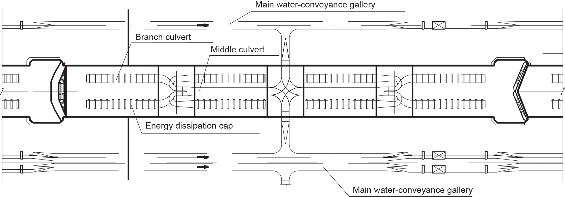
Fig.9 Layout of the water-filling and water-emptying system of the Three Gorges ship lock.
To improve the working cavitation number of the valve in the design of the Three Gorges ship lock, an integrated anti-cavitation technology of the valve in the high-head ship lock was proposed. The core proposition was “a high cavitation number water-conveyance gallery, quick-opening valve, bottom-expanded gallery, and natural ventilation by lintel.” The details are as follows:
(1) Taking advantage of the good rock mass, the main gallery of the water conveyance is separated from the lock head and chamber. As lowering the elevation of the gallery in the valve section has a minor impact on the work quantities of the ship lock's main structure, the buried depth of the gallery in that section is reasonably increased as a major measure to improve the valve's working cavitation number.
(2) The advantage of a quick-opening mode is to use the water head due to the inertia during the opening process of the valve, which can greatly increase the flow pressure and cavitation number behind the valve. In the meantime, a vortex due to enhanced bottom cavitation by the flow attached to a valve in slow-opening mode is unlikely to occur. In the Three Gorges ship-lock design, a quick-opening valve measure is adopted by taking advantage of the characteristics of the long water-conveyance gallery, in order to increase the inertia of the water head during the opening process. Thus, the flow pressure and cavitation number behind the valve are greatly improved.
(3) Change in the shape of the valve gallery usually leads to change in the hydraulic parameters behind the valve to a relative large degree; these parameters include the flow pattern, the pressure and flow velocity of the contraction section, and so forth. After a comprehensive comparison, a bottom-expanded gallery with a simple structure and a definite stress pattern was proposed. With the expanded bottom, the flow section behind the valve is enlarged. The jet velocity of the contraction section is lowered because of the reduction of the contraction, and the pressure and cavitation number behind the valve are obviously improved. This kind of shape also greatly improves the primary condition of the valve cavitation, and thus reduces the critical cavitation number of the bottom-expanded valve. Therefore, the relative cavitation number of the bottom-expanded valve is clearly increased, and its anti-cavitation ability is much better than that of the traditional top-expanded valve [20].
(4) The measurement of natural ventilation by lintel, which was invented in China, with negative pressure step, was successfully applied to the Gezhouba #1−#3 ship locks. To meet the conditions of the Three Gorges ship lock, the measurement was optimized with a different sealing slit and step height. A diffusion type of lintel somatotype was chosen. The experiments show that the ventilation is functional during the valve opening, and that the water flow cavitation is eliminated under normal valve operation when using this somatotype. In addition, the valve lip cavitation is effectively restrained. Valve lip cavitation exists in varying degrees in abnormal operation conditions such as one-sided valve opening, accident stopping, emergency moving water closure, and so forth.
The hydraulic characteristic and valve cavitation situation of the ship-lock water-conveyance system have been observed under the designed hydraulic index [21,22]. It turns out that all the lock chambers' water-conveyance systems operate well, the water flow from each section of the chambers is uniform in the whole water-filling process, and the water flow at the water surface is steady without an obvious transverse or longitudinal flowing trend. The measured water surface maximum rising (falling) speed is 4.04 m·min−1 in the chambers. The maximum flow is 700 m3·s−1, and the water-conveyance time is about 10 min for each lock head. Compared to the design allowance of 12 min, there is plenty of spare time. The ship mooring force of each chamber is normal, and the chamber pooling condition is functional.
During the water conveyance, a jetting flow noise exists due to the top water seal detaching from the lintel at the beginning of the valve opening (at about 15 s). The value in a 100 kHz sound spectrum of underwater noise rises discontinuously during 50−460 s in different positions of the middle lock head's valve section, but the maximum spectrum difference is within 20 dB. Therefore, there is no obvious cavitation noise or abnormal noise at the lock head. The volume of free air flow is more than 0.1 m3·s−1 when the opening of the lintel vent pipe is 2%−66%. The hoist operates well during the valve opening, and the maximum hoisting force is 1398 kN, which is within the design value of 1800 kN. In brief, it has been proved that the integrated anti-cavitation technology of the water-conveyance valve in the Three Gorges ship lock is successful.
《4.2. Design theory of the fully lined ship lock》
4.2. Design theory of the fully lined ship lock
The Three Gorges double-line continuous five-step ship lock is arranged at the left bank of the dam site. Each line has six lock heads and five lock chambers. The main structure is 1.6 km long, and it was necessary to build it in the mountain by excavating the rock mass, with a maximum excavated depth of 170 m. If a traditional gravity ship-lock structure had been adopted, the amount of excavation and concrete would have been huge, the construction period would have lasted a long time, and the high slope would have been extremely complex [23]. Based on the geological conditions of the location of the Three Gorges ship lock, a new ship-lock type named the “fully lined ship lock” was proposed instead. For this kind of ship lock, the lock head and the side wall of the lock chamber are all lined with a thin reinforced concrete lining. This lining works with the rock masses to jointly bear the loads from the miter gate, water pressure, and ships, through specially developed tension-shear high-strength structural bolts. Using this type of ship lock effectively reduces the amounts of rock excavation and concrete required, and also reduces the complexity of the high slope. The Three Gorges ship lock, with its double lines and five steps, is the first fully lined ship lock in the world. It was built and put into operation in 2003. Fig. 10 shows a typical cross-section of a lock chamber. Compared with a traditional gravity ship lock, the rock excavation was reduced by 8.4 × 10⁶ m3, 6 × 10⁶ m3 of concrete was saved, and nine months of construction were avoided.
The cooperative work of the concrete, rock mass, and bolts is taken into consideration for the fully lined ship lock. The contact relation between the lining and the rock mass should be considered in the calculation, and nonlinear mechanics behaviors exist for both. Therefore, the structural analysis and design of a fully lined ship lock is much more complicated than that of a normal ship lock. A complete set of design theory, method, and technical criteria for a fully lined ship lock was researched and established in the design and study of the Three Gorges ship lock [24].
The key of a fully lined ship-lock structural analysis is the accurate simulation of contact between the lining and the rock mass. In conventional contact constitutive behavior, it is assumed that when a contact surface is closed, the interface is able to carry a tangential force not bigger than the shear strength. When the interface is open, there is no more shear stiffness or tangential force. In fact, since the rock surface is not absolutely smooth after excavation, a bite force comes into being with the concrete lining. Even if there is a slight gap between the lining and the rock, the tangential bite force still exists. A part of the lining structure of the Three Gorges ship lock may sometimes be disconnected from the rock under certain temperatures, causing the contact surface between the rock mass and the concrete lining to be partly open. Adopting a traditional interface constitutive relationship would greatly underestimate the real tangential bite force between the rock mass and the lining surface. Therefore, a new interface constitutive relationship between the lining and rock, which considers the tangential bite force of the interface, was proposed. Assuming that the original contact surface normal gap is d, that two original gaps in the tangential direction are dt′ and ds′, respectively, and that the relative displacement increments in both the normal and the tangential directions at both sides of the joint surface are Δ Wn, Δ Vt, and Δ Vs, respectively, under the effect of load increment, then the physical equation for the contact surface between the lining and the rock can be expressed by Eq. (6) [24]:
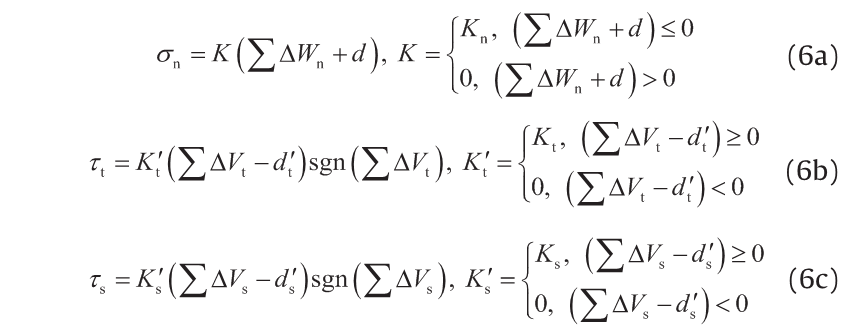
where, σn is the normal stress on the contact surface; τt and τs are the tangential stresses on the contact surface, respectively; Kn is the normal stiffness in the unit area of the joint surface; and Kt and Ks are the tangential stiffnesses in the unit area of the joint surface, respectively. The sgn(∑ ΔVt) represents the relative displacement difference ∑ ΔVt.
Due to the force from the rock mass behind the wall, the thickness of the lining has a minor effect on the stress conditions of the wall. The lining thickness of the chamber mainly depends on the bolts' structural arrangement in the wall and on the construction requirements. The minimum thickness of the lining wall can be pre-determined using Eq. (7) [25]:

where, δR is the minimum anti-pullout thickness of the bolt; δD is the thickness of the anchor head; δC is the cover thickness.
For a lined structure, the cooperative work between the concrete and the rock mass is ensured by the high-strength bolts. These bolts not only endure the tensile force caused by seepage pressure, but also withstand the shear force caused by the deformation of the lock wall. The bearing capacity of bolts in a concrete lining wall is determined by the uplift shear cone of the concrete or by the strength of the bolts; and the bolts' strength must meet the conditions in Eq. (8) [25]:
《Fig. 10》

Fig.10 A typical cross-section of a lock chamber of the Three Gorges Project.

where, Pu is the tensile force of the bolts; Vu is the shear force of the bolts; Pc is the tensile force of the concrete when the uplift cone reaches yield failure; Vc is the shear force of the concrete when the uplift cone reaches yield failure; Ps is the tensile force of the bolt when it reaches yield strength; Vs is the shear force of the bolt when it reaches yield strength; V1 is the safety factor of the strength of the bolt, taken as 1.9; φ1 and φ2 are factors, taken as 1 and 0.85, respectively.
A “free section” is set in the high-strength bolt between the lining and the rock. This section is able to deform freely, and can effectively reduce the constraint of the bolts on the tangential deformation of the wall body in order to lower the shear stress and improve the stress condition at the spanning joint of the bolt. It gives full play to the features of the bolts, which have a high tensile strength and a low shearing strength.
As of December 2015, the Three Gorges ship lock has been running for 12 years, including five years of trial water storage. The detailed monitoring data is as follows: ① The maximum tensile stress of the locked anchor is smaller than 100 MPa; ② regarding the underground water in the slope, the water levels of most piezometers in the drainage tunnel are lower than the bottom level of the tunnels; ③ regarding the osmotic pressure behind the lining, the values of the osmometer are nearly zero, indicating that the drainpipes behind the lining wall play a beneficial role in reducing the osmotic pressure; ④ regarding the top of the lock head, the maximum deformation toward the lock chamber is 7.1 mm, the relative deformations of the top and bottom of the lock head are within 5 mm, and the maximum horizontal deformation toward the lock chamber of the cable galleries in the northern and southern top locks is 6.9 mm; and ⑤ regarding the high-strength bolts in the vertical slopes, only two bolts have tensile stress greater than 100 MPa, and the measured stress values are much smaller than the design strength values. The above monitoring results show that the ship-lock slope is stable; that the underground water in the slope, the osmotic pressure on the back of the wall, the deformation of the lock head and lock chamber wall, and the stress of the high-strength structure anchor are all within the permissible range; the water-conveyance system operates well; and that the main technology indexes have reached or exceeded the design standard.
《5. Conclusions》
5. Conclusions
During the design and construction of the Three Gorges Project, a series of technological challenges and scientific and technological innovations were continually confronted. The engineers insisted on cross-industry collaborative innovation in science and technology, adhered to the original innovation and the secondary innovation, and insisted on technological innovation to solve the actual problems of the engineering construction. The series of technological problems included flood discharge and energy dissipation with a high water head and large discharge, a multi-layer large orifice gravity dam, a giant power station structure, a large-scale ship lock with a high water head, and so forth. These problems have been overcome, and a large number of world-leading science and technology innovations have been achieved. Since the implementation of experimental storage at the normal water level of 175 m in 2008, the reservoir has reached the normal level for six consecutive years, from 2010 to 2015. The project fully provides the comprehensive benefits of flood control, power generation, navigation, water supply, and so on, and successfully experienced a maximum inbound peak flow of 7.12 × 10⁴ m3·s−1. Since the operation of the hydraulic structures began, the monitoring results show that the monitoring data such as deformation, seepage, stress-strain values, and so forth, are all lower than the design and calculation values, indicating that the structure's condition is normal and its operation is safe and reliable. The successful practice of the Three Gorges Project greatly improves the overall technological level of water resources and hydropower construction in China. Many innovative technologies developed in the Three Gorges Project have been widely applied to follow-up water resource and hydropower projects around the world; these technologies play an immense role in promoting global water conservancy and the technological progress of the hydropower industry.


 京公网安备 11010502051620号


