

《1. Introduction》
1. Introduction
Sewage is composed of rainwater and water discharged into sewers by humans and production activities. The sewer system contains wastewater and human waste from houses, offices, and factories. In Japan, the volume of sewage in fiscal year (FY) 2011 was about 1.45 × 10¹⁰ m3 [1]. Thus, sewage is considered to have a huge energy potential. The extent of biogas power generation from sewage sludge and of hydraulic power generation from sewage are estimated to be 3.6 × 10⁹ kW·h·a-1 and 4 × 10⁷ kW·h·a-1, respectively, and sewage heat is evaluated to be 7800 Gcal·h-1 (1 Gcal·h-1= 1.163 MW) [2]. The Japanese government aims to utilize sewage as an energy resource. However, the rate of utilization remains extremely low; the energy utilization rate of sewage sludge is approximately 13%, the number of sewage heat supply facilities is 14, and the number of small-hydraulic power plants is 13 [2].
Sewage facilities comprise drainage facilities such as sewage pipes, treatment facilities such as treatment plants, and complementary facilities such as pump stations. The abovementioned estimation of the hydraulic energy potential seems to be restricted to the treated water discharged from treatment facilities. In Japan, the total length of sewage pipes in FY 2012 was approximately 4.5 × 10⁵ km [1], equivalent to about 11 laps of the Earth’s equator. This is slightly longer than the combined length of irrigation channels of 4 × 10⁵ km [3]. Therefore, it is presumed that hydraulic energy potential is dispersed in sewage pipes around the country. Consequently, the utilization of sewage flowing in drainage facilities (sewage pipes) for power generation promises to realize small-scale distributed power generation, which could contribute to the local production of electric power for local consumption. However, such sewage power generation has never been conducted, and the hydraulic energy potential in the drainage facilities has not yet been investigated.
In Japan, hydropower is also receiving much attention because it is a promising renewable energy resource that is largely unaffected by the weather. As large-scale hydroelectric plants having outputs of more than 100 MW require huge dams and long conduits, few locations for such plants remain undeveloped. Thus, there is an increasing desire to realize micro-scale hydraulic power generation with an output of less than 100 kW. Such power generation can utilize small-scale hydropower, which is widely distributed in small rivers and irrigation canals in Japan. Consequently, several small-scale hydraulic turbines have been developed [4-9]. Such micro-hydraulic turbines are frequently blocked with foreign matter such as fallen leaves, twigs, and refuse, and they occasionally lose their function. A filter installed upstream of the micro-hydraulic turbine can remove the foreign matter. However, such equipment increases the operation cost of micro-hydraulic turbines. We are engaged in the development of a pico-hydraulic turbine with excellent performance in the passage of foreign matter [10,11]. The runner has a circular hollow around the central axis so that foreign matter can pass through the runner. The efficiency and foreign matter passage performance of this hollow pico-hydraulic turbine are being studied through laboratory experiments and demonstration experiments in a small river. Sewage contains hair and vegetable waste from home bathrooms and kitchens, as well as human waste. To successfully generate power from sewage, it is essential that the hydraulic turbine is not blocked by foreign matter. Therefore, the hollow pico-hydraulic turbine we are developing promises to be effective for sewage power generation applications.
The objective of this study is to search for possible hydraulic power generation from the sewage flowing in pipes. First, the present study focuses on the Toyogawa River-Basin Sewerage [12] in Aichi Prefecture, which is located in the central region of Japan. It explores the sewage flow rate at the two connection points over the course of a year to clarify the hydraulic energy potential of the sewage. Second, this study investigates the efficiency and foreign matter passage performance of the hollow pico-hydraulic turbine in laboratory experiments that suppose the turbine to be installed in the sewage pipe at the connection points.
《2. Flow duration and hydraulic potential of Toyogawa River-Basin Sewerage》
2. Flow duration and hydraulic potential of Toyogawa River-Basin Sewerage
《2.1. Outline of Toyogawa River-Basin Sewerage》
2.1. Outline of Toyogawa River-Basin Sewerage
The Toyogawa River-Basin Sewerage treats the sewage from four cities (Toyohashi, Toyokawa, Gamagori, and Shinshiro) in the eastern region of Aichi Prefecture, Japan [12]. The total sewerage area is about 46 km2, the population is about 200 000, and the treatment capacity is 1.04 × 10⁵ m3·d-1 (as of April 1, 2015). The Toyogawa River-Basin Sewerage has four trunk lines: the Toyohashi, Tobu, Seibu, and Mito. The total length is about 36 km. The sewage treated in the Toyogawa wastewater treatment plant is discharged into Mikawa Bay. Fig. 1 shows the positional relations between the trunk lines, the wastewater treatment plant, and Mikawa Bay.
《Fig. 1》

Fig.1 Trunk lines and connection points of Toyogawa River-Basin Sewerage in Japan.
The Toyogawa River-Basin Sewerage is connected with public sewerage systems managed by the four cities. The connected part is called the connection point. The Toyogawa River-Basin Sewerage has 27 connection points. Fig. 1 uses circular symbols to depict the connection points to the Toyogawa River-Basin Sewerage. At the connection points, the sewage pipe is an open channel, and the sewage flow rate is measured throughout the year. This study investigates the flow rate at two connection points, Toyohashi 1 and Tobu 11-2, to search for possible hydraulic power generation from the sewage. Fig. 2 shows a photograph of the sewage pipe and sewage at the connection point Toyohashi 1.
《Fig. 2》
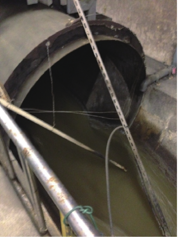
Fig.2 Sewage pipe and sewage at the connection point Toyohashi 1.
《2.2. Flow duration at connection points》
2.2. Flow duration at connection points
When constructing a hydraulic power plant, the daily mean water flow rate is measured in advance at the construction site over the course of a year to accurately estimate the power output. By arranging the daily mean water flow rates in descending order, a flow duration curve is constructed. Fig. 3 shows the flow duration curves at the connection points Toyohashi 1 and Tobu 11-2 in FY 2013. In a flow duration curve, the 95th, 185th, 275th, and 355th largest flow rates are called high water discharge, ordinary water discharge, low water discharge, and droughty water discharge, respectively. In Fig. 3, such flow rates are denoted by Q1, Q2, Q3, and Q4, respectively, and they are listed in Table 1. At the connection points Toyohashi 1 and Tobu 11-2, the ratios of the difference in the high and low water discharges ( Q1- Q3) to the ordinary water discharge Q2, ( Q1- Q3)/ Q2, are 0.138 and 0.093, respectively, demonstrating that the yearly flow rate variation is low. This is also confirmed by the fact that the gradient of the duration curve at Q2 is shallow.
《Fig. 3》

Fig.3 Flow duration at the connection points in FY 2013. (a) Toyohashi 1; (b) Tobu 11-2.
《Table 1》
Table 1
Sewage flow rates at Toyohashi 1 and Tobu 11-2.
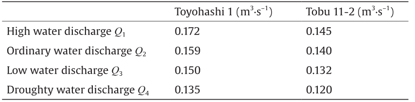
Fig. 4 shows the sewage flow rate at the connection point Toyohashi 1, where the mean, minimum, and maximum flow rates for every month of the year are indicated. The mean and minimum values are almost the same, and they are nearly equal to the ordinary water discharge Q2. However, the maximum flow rate for every month is much larger than the mean, except in July, November, December, and January. The yearly change is also larger than the mean and minimum flow rates. As the Toyogawa River-Basin Sewerage is a separated sewer system, only the sewage should flow in the sewage pipe; however, so-called “uncertain water,” such as rainwater, is also considered to flow with the sewage in the pipe. The top column of Fig. 4 shows the monthly precipitation in the city of Toyohashi. The distance between the observation point and the connection point, Toyohashi 1, is about 7 km. In the months when precipitation is high, the sewage flow rate is also high. This trend is most marked in September and October. The reason that the maximum sewage flow rate is much higher than the mean, and fluctuates markedly, is that rainwater also flows in the sewage pipe.
《Fig. 4》

Fig.4 Monthly sewage flow rate and precipitation at the connection point Toyohashi 1.
Fig. 5 shows the change in the sewage flow rate at the connection point Tobu 11-2, alongside the monthly precipitation in the city of Toyohashi. The mean and minimum flow rates are almost the same, but the maximum flow rate is much higher in August, September, and October. This may also be caused by rainwater flowing in the sewage pipe.
《Fig. 5》
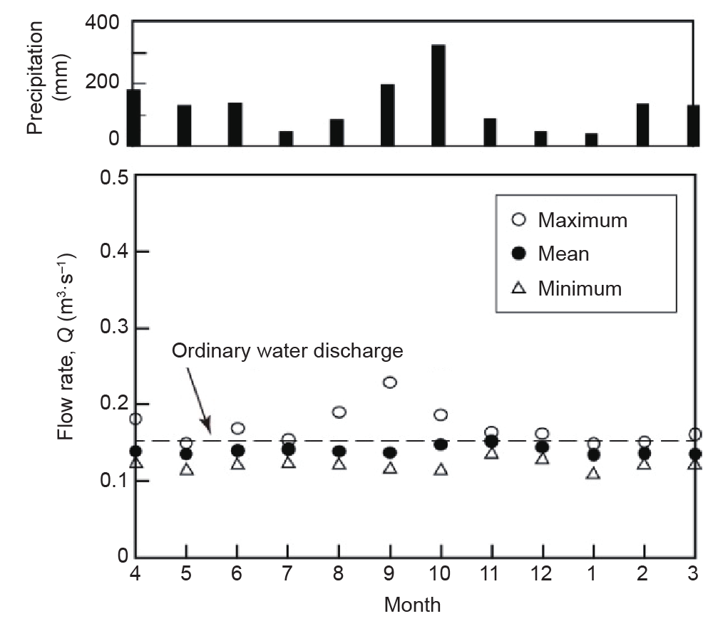
Fig.5 Monthly sewage flow rate and precipitation at the connection point Tobu 11-2.
The maximum monthly sewage flow rate reaches a maximum value in September, as shown in Fig. 4 and Fig. 5. Fig. 6 shows the daily mean flow rate at the connection points Toyohashi 1 and Tobu 11-2 in September. On September 16, when the daily precipitation was 120 mm, the daily mean sewage flow rate reached its maximum value; this observation further confirms that rainwater increases the sewage flow rate.
《Fig. 6》

Fig.6 Daily mean flow rate and precipitation at the connection points Toyohashi 1 and Tobu 11-2 in September.
《2.3. Hydraulic potential at connection points》
2.3. Hydraulic potential at connection points
The hydraulic potential of fluid flowing with velocity u, that is, P, is expressed as

where, ρ is the fluid density and Q is the flow rate.
The diameter of the sewage pipe at the connection point Toyohashi 1 is 1000 mm. The sewage does not always flow across the whole cross-section of the pipe; rather, it flows along the bottom of the pipe, as shown in Fig. 2. If the sewage is assumed to occupy 10% of the cross-sectional area of the pipe, the velocity u can be calculated from the flow rate Q. When u is calculated at the ordinary water discharge Q2, which is 0.159 m3·s-1, the output P is estimated to be 328 W based on Eq. (1), where the density of water is used for ρ. Applying a similar calculation to the connection point Tobu 11-2 yields an output P of 222 W.
The abovementioned hydraulic potential P can be converted to electric power by a generator driven by a hydraulic turbine. Considering the efficiencies of the generator and the hydraulic turbine, the electric power is evaluated to be 0.2 P. The electric power at the connection points Toyohashi 1 and Tobu 11-2 is 66 W and 44 W, respectively. These values are assumed to remain unchanged throughout the year, because the change in the sewage flow rate is small, as demonstrated in Fig. 3. The power consumption of a ventilating fan with a diameter of around 250 mm is about 25 W, and that of an LED light bulb whose luminance is equivalent to a fluorescent lamp of 60 W is about 10 W. Thus, the electric power generated from the sewage can be used for ventilation and illumination at the connection points.
《3. Hollow pico-hydraulic turbine》
3. Hollow pico-hydraulic turbine
A hydraulic turbine is needed to convert the hydraulic potential at the connection points Toyohashi 1 and Tobu 11-2 into electric power. The sewage contains hair and vegetable waste from home bathrooms and kitchens, as well as human waste. Therefore, hydraulic turbines that will not be blocked by such foreign matter are urgently needed.
Micro-hydraulic turbines, which can be installed in small rivers and irrigation canals for power generation, are frequently blocked by foreign matter, such as fallen leaves, twigs, and refuse. As such blockage causes a reduction in turbine performance, the development of a micro-hydraulic turbine with excellent foreign matter passage performance is desired. We are engaged in the development of a pico-hydraulic turbine [10,11], in which the runner has a circular hollow around the central axis so that foreign matter can pass through without blocking the hydraulic turbine. This hollow pico-hydraulic turbine is considered to be useful for power generation from sewage. This study explores its applicability by means of laboratory experiments.
Fig. 7 shows the cross-section of the hollow pico-hydraulic turbine. A circular pipe (hatched with red in the diagram) is inserted between two stationary pipes, with their axes on a line. The inserted pipe is supported by two bearings; thus, the pipe can rotate around the central axis. A runner (shown in blue in the diagram) is embedded within the inserted (rotational) pipe. When water flows in the pipe, the runner and the pipe rotate integrally around the axis. The inner diameter of the stationary and rotational pipes is 80 mm, and the axial length of the rotational pipe is 195 mm. A guide vane (shown in green) is mounted at the end of the stationary pipe, just upstream of the rotational pipe.
《Fig. 7》
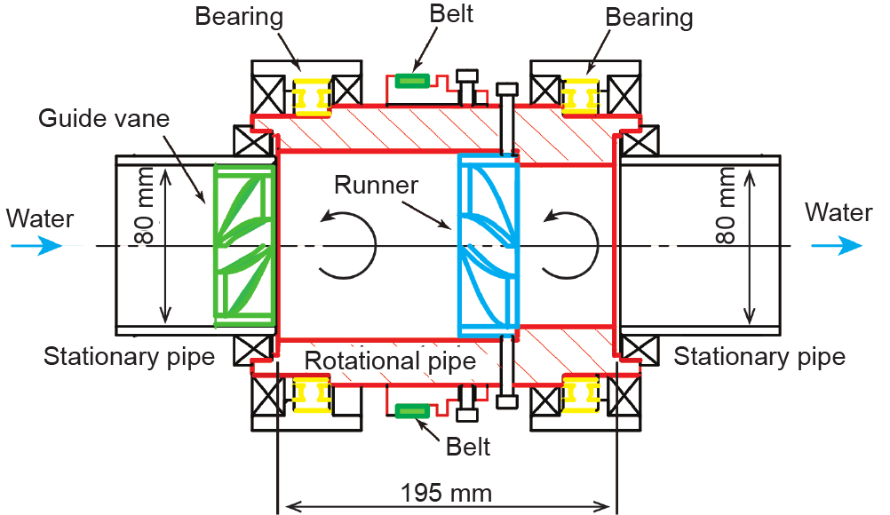
Fig.7 Cross-section of the hollow pico-hydraulic turbine.
Fig. 8 shows an example of the runner. It has four blades, and a circular hollow is provided around the rotating (central) axis so that foreign matter included in the water can pass through the runner. The ratio of the hollow diameter D2 to the pipe diameter D1, which is 80 mm, is defined as the hollow ratio ε = D2/ D1. The ε value for the runner shown in Fig. 8 is 0.375.
《Fig. 8》

Fig.8 Runner with ε = 0.375.
The runner is composed of a flat plate cascade. Fig. 9 shows the 2D development view, and Table 2 lists the specifications of the blade. The width B is 23 mm, the thickness t is 5 mm, and the inlet and outlet angles, α1 and α2, respectively, are 70°. This study conducts pioneering experiments to explore the foreign matter passage performance of a pico-hydraulic turbine. Since the runner is preliminarily designed in this study, the specifications could be modified to improve the performance.
《Fig. 9》

Fig.9 2D development view of runner blade.
《Table 2 》
Table 2
Blade specifications.
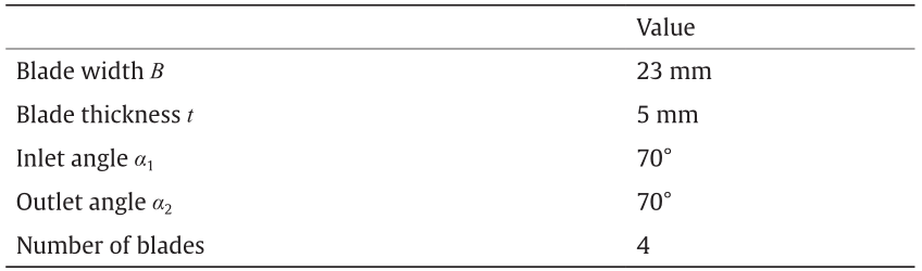
Fig. 10 shows an example of the guide vane. A hollow is also provided around the central axis. The diameter is the same as that of the runner.
《Fig. 10》

Fig.10 Guide vane with ε = 0.25.
Fig. 11 presents a 3D cut model of the hollow pico-hydraulic turbine. The runner rotates with the outer pipe around the axis. The rotational motion is transmitted to a generator or a torque meter through a belt.
《Fig. 11》

Fig.11 3D cut model of the hollow pico-hydraulic turbine.
《4. Laboratory experiment with hollow pico-hydraulic turbine》
4. Laboratory experiment with hollow pico-hydraulic turbine
《4.1. Experimental method and conditions》
4.1. Experimental method and conditions
To investigate the performance of the pico-hydraulic turbine,laboratory experiments were conducted using the closed-loop test rigshown in Fig. 12. Water in the tank is circulated by a pump and thecirculated water drives the pico-hydraulic turbine. The pipes upstreamand downstream of the pico-hydraulic turbine are made of transparentacrylic resin so that the behavior of foreign matter entrained inthe loop can be observed. The pressures are measured at two points,320 mm upstream and 183 mm downstream of the pico-hydraulic turbine.The water flow rate is measured by a propeller-type flowmeter mountedin a bypass pipe upstream of the pico-hydraulic turbine. To detectthe turbine output, the torque is measured with a torque meter drivenby the turbine. The rotational speed of the turbine, which is alsomeasured by the torque meter, is controlled by a powder brake connectedto the torque meter.
《Fig. 12》

Fig.12 Closed-loop test rig for laboratory experiments.
The efficiency of the pico-hydraulic turbine, η, is defined as

where, T is the torque; ω is the angular velocity; Q is the flow rate; and P1 and P2 are the pressures upstream and downstream of the turbine, respectively.
Fig. 13 shows the runners employed in this study. Runner 1 was used in prior experiments [10,11]. Runner 2 is a revised runner; the blade leading edge is rounded so that it does not hook foreign matter, and the radius is 15 mm.
《Fig. 13》
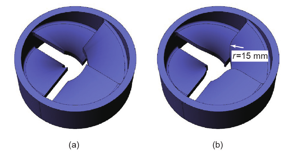
Fig.13 (a) Runner 1; (b) Runner 2. ( D1 = 80 mm, ε = 0.25)
Fig. 14 shows the guide vanes used in this experiment. Guide vane 1, which has eight blades, was employed in prior experiments [10,11]. Guide vane 2 has eight tapered blades with a taper angle of 30°. Guide vane 3 has the same blades as Guide vane 1, but the number of blades is reduced to four.
《Fig. 14》

Fig.14 (a) Guide vane 1; (b) Guide vane 2; (c) Guide vane 3. ( D1 = 80 mm, ε = 0.25)
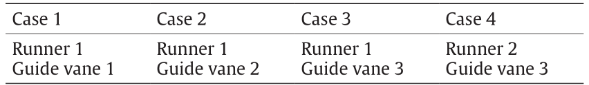
This study investigates the turbine performance for four combinations of runners and guide vanes, as listed in Table 3. The water flow rate Q is 0.01 m3·s-1.
《Table 3 》
Table 3
Combinations of runners and guide vanes.
To investigate the performance of the pico-hydraulic turbine when installed in a sewage pipe under laboratory conditions, the foreign matter contained in sewage should be replaced with matter that is easily handled in the laboratory. The mass of solid matter included in 1 m3 of domestic wastewater is estimated to be 0.2 kg, and 97% of human waste is considered to be moisture; thus, sewage is regarded as being almost all water. As the hair and fiber waste contained in sewage discharged from houses do not easily decompose, they flow down the sewage pipes. There is concern that the pico-hydraulic turbine will be readily blocked by hair and waste. Therefore, this laboratory experiment used polyester fibers to simulate foreign matter in the sewage pipe. The fibers are shown in Fig. 15. The diameter and mass of each spherically shaped fiber were about 20 mm and 0.2 g, respectively. The fibers were released into the water from the outlet pipe of the tank, which was located upstream of the pico-hydraulic turbine. The time interval between the releases was 3 min.
《Fig. 15》
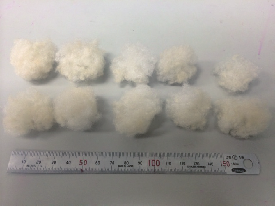
Fig.15 Polyester fibers.
《4.2. Efficiency of the pico-hydraulic turbine under fiber-free conditions》
4.2. Efficiency of the pico-hydraulic turbine under fiber-free conditions
First, the efficiency of the pico-hydraulic turbine, η, was explored without releasing the polyester fibers into the water. We investigated η for Case 1 in previous studies [10,11]. Fig. 16 shows the effect of the hollow ratio ε on the relation between η and the rotational speed N for Case 1. The experimental data for each hollow ratio are composed of three measurements. When the runner has no hollow ( ε = 0), the maximum value of η, ηmax, is 0.186, and the N value at ηmax is Nmax = 496 r·min-1. For the runner with ε= 0.25, ηmax and Nmax are slightly reduced, but the reductions are not significant. When the hollow ratio ε is further increased to 0.375 and 0.5, ηmax is greatly reduced, and a marked reduction of Nmax also occurs. This is because the area of the blade is decreased; accordingly, the energy of the water is not fully transferred to the pico-hydraulic turbine. On the basis of the abovementioned results, the performance of the pico-hydraulic turbine having the runner with ε = 0.25 was explored for Cases 2, 3, and 4, because the performance deterioration due to the hollow was not very significant.
《Fig. 16》

Fig.16 Dependence of turbine efficiency on hollow ratio under fiber-free condi.
Fig. 17 compares the pico-hydraulic turbine efficiencies for Cases 1, 2, 3, and 4, where the hollow ratio εis 0.25 and the polyester fibers are not released into the water. The value of η for Case 1 is the highest. For Case 2, employing a guide vane with tapered blades (Guide vane 2) reduces η. This is because the area of the blades is smaller than that of the guide vane used for Case 1, and accordingly the water is not fully straightened. The value of η for Case 3 is lower than that for Case 2. Although the runner in Case 3 is the same as that for Cases 1 and 2, the guide vane (Guide vane 3) only has four blades. Therefore, the water flow upstream of the runner is not fully straightened. The value of η for Case 4 is the lowest; although the guide vane is the same as that in Case 3, the runner (Runner 2) has blades whose leading edge is rounded with the r = 15 mm; in addition, the blades are smaller than those of Runner 1. Such a reduction of blade area also deteriorates the turbine performance.
《Fig. 17》

Fig.17 Turbine efficiency under fiber-free conditions when ε = 0.25.
《4.3. Change in efficiency due to entrained fibers》
4.3. Change in efficiency due to entrained fibers
Fig. 18 shows the relation between the pico-hydraulic turbine efficiency η and the mass of the fibers mf released into the water. The fibers are released at the rotational speed Nmax, where η reaches the maximum value ηmax under fiber-free conditions. Thus, η at mf = 0 g corresponds to ηmax. The released fibers cause η to decrease. The value of η for Case 2, employing the tapered guide vane, is higher than that for Case 1 at mf >1.5 g. This is because the attachment of the fibers to the guide vane is suppressed, as mentioned later. Comparing the efficiencies for Cases 3 and 4, η for Case 4, employing the runner with the rounded blades, is higher than that for Case 3 at mf >1.8 g. The attachment of the fibers to the runner is also suppressed, as discussed later.
《Fig. 18》

Fig.18 Change in turbine efficiency due to entrained fibers.
Fig. 19 compares the efficiencies for Cases 1, 2, and 3, where η is normalized by ηmax. The ratio η/ ηmax for Case 1 is almost the same as that for Case 3, but η/ ηmax for Case 2 is higher. The guide vane (Guide vane 2) employed for Case 2 is considered to have excellent fiber passage performance.
《Fig. 19》
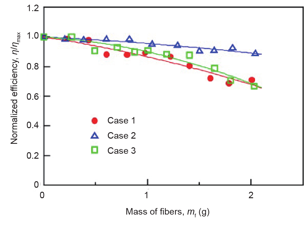
Fig.19 Change in turbine normalized efficiency due to entrained fibers for Cases 1, 2, and 3.
Fig. 20 shows photographs of the guide vanes after the experiments for Cases 1, 2, and 3. The fibers are attached to the leading edge for Case 1, and the inlet is partially blocked by the fibers for Case 3. In contrast, fibers are barely observed for Case 2. The masses of fibers attached to the guide vane for Cases 1, 2, and 3 are 0.312 g, 0.027 g, and 0.170 g, respectively. The tapered guide vane (Guide vane 2) is superior in its suppression of the attachment of the fibers.
《Fig. 20
》
Fig.20 Photographs of guide vanes for Cases 1, 2, and 3.
Fig. 21 compares the efficiencies for Cases 3 and 4; Guide vane 3 is employed in both cases. The decrement in η/ ηmax for Case 4 is smaller than that for Case 3, and it is considered that the runner (Runner 2) with rounded blades has excellent fiber passage performance.
《Fig. 21》

Fig.21 Change in turbine normalized efficiency due to entrained fibers for Cases 3 and 4.
Fig. 22 shows photographs of the runners after the experiments for Cases 3 and 4. In Case 3, fibers are attached to the leading edge of the blades. This is because the leading edge has a sharpened end and, therefore, hooks the fibers. For Case 4, no fibers are present. The masses of the fibers attached to the runner for Cases 3 and 4 are 0.06 g and 0 g, respectively. It is found that the employment of rounded blades (Runner 2) is very useful in improving the passage performance of the fibers.
《Fig. 22》

Fig.22 Photographs of runners for Cases 3 and 4.
The pico-hydraulic turbine can be installed in a sewage pipe at the connection point, as outlined in Fig. 23. It is designed so as to be suspended by a crane, because it is important to facilitate its maintenance.
《Fig. 23》

Fig.23 Install of pico-hydraulic turbine in sewage pipe at connection point.
《5. Conclusions》
5. Conclusions
To search for possible pico-hydraulic power generation from sewage in pipes, the flow durations at two connection points of the Toyogawa River-Basin Sewerage were investigated, and the hydraulic potential of the sewage was estimated. The investigation indicates that the connection points Toyohashi 1 and Tobu 11-2 have hydraulic potential, which can be used for power generation throughout the year.
The efficiency and foreign matter passage performance of the hollow pico-hydraulic turbine were explored through laboratory experiments that supposed the pico-hydraulic turbine to be installed in the sewage pipe at the connection points. The exploration makes it clear that a runner with rounded blades and guide vanes with tapered blades can suppress the attachment of fibers to the pico-hydraulic turbine and, therefore, improve turbine efficiency. Consequently, it was found that the hollow pico-hydraulic turbine could be employed for power generation from sewage flowing in pipes.
《Compliance with ethics guidelines》
Compliance with ethics guidelines
Tomomi Uchiyama, Satoshi Honda, Tomoko Okayama, and Tomohiro Degawa declare that they have no conflict of interest or financial conflicts to disclose.


 京公网安备 11010502051620号


