
《1.Introduction》
1.Introduction
The high-speed electrical multiple unit (EMU) is one of the most complex terrestrial mass-transportation systems in the world. It consists of dozens of systems and subsystems, hundreds of devices, and thousands of components. These systems and subsystems include traction power and brake, door control, air conditioning, light control, and more. EMU technology combines electrics, electronics, computer science, automation, mechanics, and dynamics. When a new type of EMU is put into service, not only must its design, commissioning, and testing be determined, but aspects such as driver training, operation management, maintenance periods, and tools must also be considered.
After several years of research, development, and application, the China Academy of Railway Sciences (CARS) has built an EMU life cycle cost (LCC) management system based on digital and simulation technology. The EMU LCC management system involves EMU design, developing, testing, training, operation, and maintenance phases, thus incorporating almost the whole EMU life cycle. This paper introduces the LCC management system from the point of view of the train control and monitoring system (TCMS) of the EMU at different stages, including the design, developing, testing, verification, and maintenance stages; it also discusses related technologies, tools, and platforms.
TCMS is a train-borne distributed control system. It comprises computer devices and software, human-machine interfaces (HMIs), digital and analog input/output (I/O) capability, as well as the data networks required to connect all these components together in a secure and fault-resistant manner. TCMS is the standard control, communication, and train management system for all vehicle platforms and applications, ranging from trams, metros, passenger coaches, and people movers to multiple-car trains, high-performance locomotives, and high-speed trains. The precise TCMS architecture deployed varies depending on operational requirements and the market segment, but the purpose and benefits of TCMS are common across all architectures.
The TCMS software development platform is used from the earliest stages of the conception and realization of a new type of EMU. TCMS is the brain of an EMU because it controls and monitors all onboard subsystems and devices. Thus, starting from the initial design phase, EMU systems, subsystems, interfaces, and the control logic functions between each system must be considered. Diagnostics functions and maintenance issues must also be included, such as monitoring the operating status of all the subsystem devices, and defining all the necessary diagnosis codes for each fault of TCMS and of the subsystems. Reliability, availability, maintainability, and safety (RAMS) parameters are considered as well, in order to build a flexible, convenient, and easy-to-use onboard control and monitoring system from the initial phase.
The TCMS testing and verification bench is also used during EMU LCC management. In order to implement the manufacture of a new type of EMU, several subsystems from different suppliers are integrated. For this reason, subsystems’ interfaces and control functions—which must satisfy the agreed-upon requirements between the TCMS integrator and the subsystem providers—must be tested and verified. The TCMS integration tests include communication and signal interface tests, control logic function tests, and a diagnostic function test. The use of a TCMS testing bench is also advantageous for EMU LCC management because it shortens the EMU test time and cost.
The EMU driving simulation platform is built on the base of the TCMS software development platform and the TCMS testing and verification bench. It combines visual 3D technology with EMU system function simulation models. The driver desk, operation handles, instruments, power line, and track circumstance are built by exploiting a 3D modeling technology. Driving events, conditions, and track data are inputted into the 3D EMU mechanical model and into the EMU function simulation model. The output data of the EMU function simulation model are then sent back to the 3D mechanical model in order to display, for example, the speed responses of the EMU. The EMU driving simulation platform can also be used for the operation and maintenance training of drivers and maintenance staff.
The EMU remote data transmittal and maintenance platform is used by maintenance staff in depots or workshops in order to monitor the EMU operation states from a website and then assign maintenance work on the EMUs according to operation and fault conditions. With wireless transmission devices (WTDs) installed on the EMUs, it is possible to monitor the operation statuses of onboard systems and devices and remotely download fault messages. The maintenance staff utilizes these kinds of information to assign maintenance tasks and prepare the necessary maintenance tools, consumables, and spare parts before an EMU’s return to the depot.
The TCMS software development platform, TCMS testing and verification bench, EMU driving simulation platform, and EMU remote data transmittal and maintenance platform constitute the main structure of the EMU LCC management system. With this system, system engineers can focus on LCC management from the early design phase to the operation phase, and even into the maintenance stage. It is also helpful for driver and maintenance staff training. During the operation stage, the system also benefits maintenance work in the depot. In addition, the depot application feedbacks and maintenance experiences may be inputted into the EMU remote data transmittal and maintenance platform in order to continuously improve EMU performance, subsystem control, and diagnostic functions.
《2.The TCMS software development platform and the TCMS testing and verification bench》
2.The TCMS software development platform and the TCMS testing and verification bench
Together, the EMU TCMS software development platform and the TCMS testing and verification bench are a unified platform for TCMS software design and verification and for hardware and software integration testing. The platform development includes the environment for the development of visual application software, for the integration of embedded applications and the real-time operating system, for the development of network control units interface driver packages, and for the synchronized development and collaborative testing of the design and verification software.
《2.1. The TCMS software development platform》
2.1. The TCMS software development platform
TCMS is an onboard system built with the purpose of controlling and monitoring almost all the train equipment and functional processes. TCMS applications include scalable hardware models and software function blocks, which comply with the vehicle builders’ requirements. Based on the control and monitoring architecture, TCMS centralizes all the information related to the operating status of all the so-called “intelligent” train equipment.
The TCMS software development platform has the following characteristics:
• It provides the hardware driver for central processing unit (CPU) and I/O interfaces.
• It provides function block diagram (FBD) libraries.
• It provides the diagnostic block function and data storage function.
• It automatically compiles, links, and generates the executable code.
• It provides online monitoring tools for commissioning and investigation.
Fig. 1 shows the structure of the TCMS software development platform.
《Fig. 1》
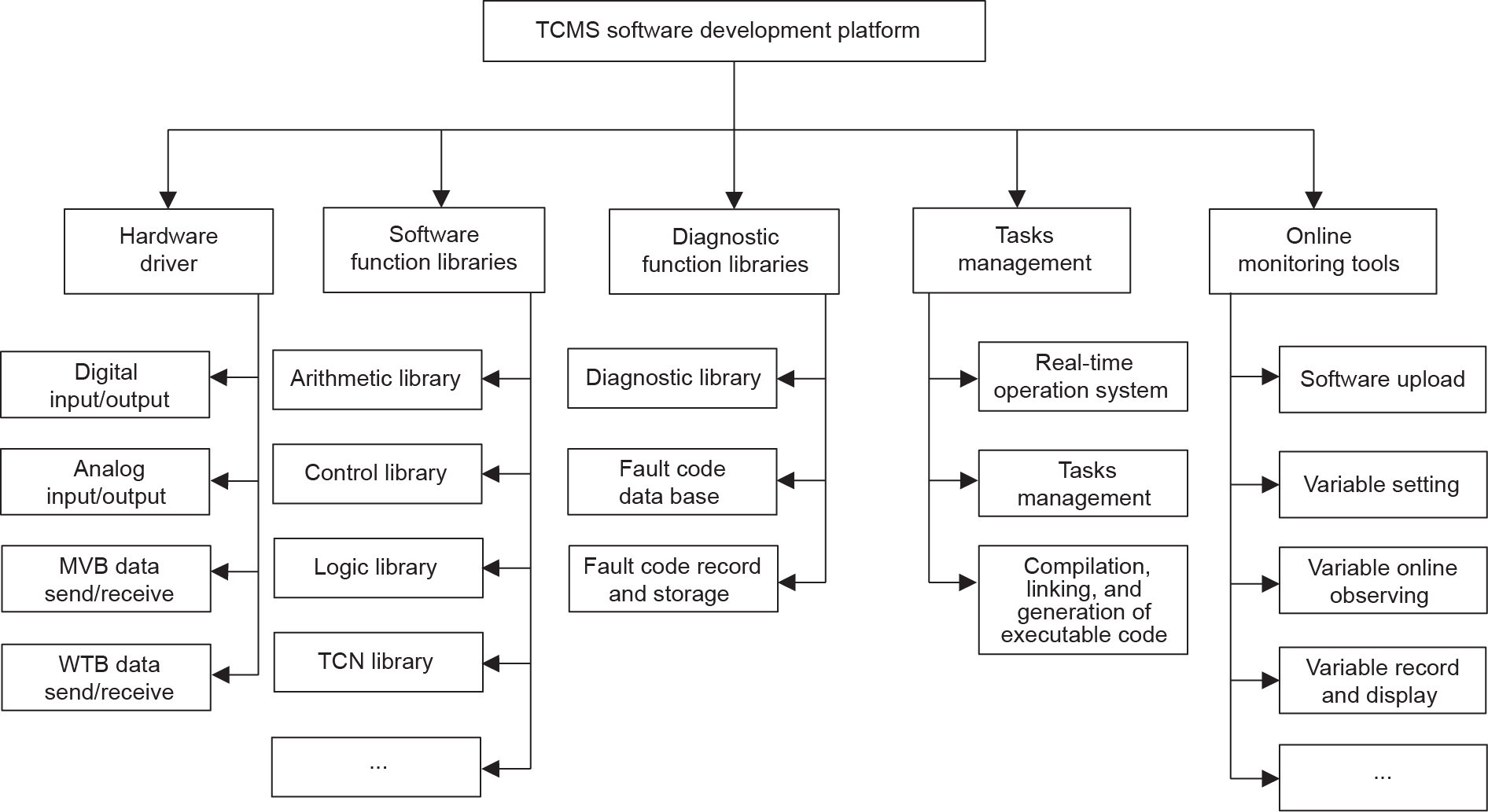
Fig. 1. The TCMS software development platform structure. MVB: multifunction vehicle bus; WTB: wired train bus; TCN: train communication network.
《Structure and application》
Structure and application
The TCMS software development platform relies on the basic software ControlBuild, a systems engineering software tool. ControlBuild supports the IEC 61131-3 (sequential function chart (SFC), ladder diagram (LD), FBD, and structured text (ST)) and electrical schematic languages. However, it is insufficient for the development of TCMS application software, so the abovementioned functional requirements must be implemented [1].
Object hardware driver development includes two main parts. The first part is the development of the driver for I/O cards, with the cards being divided into digital and analog according to the signal type. The second part is the development of the driver for the communication interface cards. Of course, most EMUs use the IEC 61375-1 train communication network (TCN) technology, which consists of the multifunction vehicle bus (MVB) normally used for intra-vehicle communication and the wired train bus (WTB) for train-wide connection and information exchange. The communication interface drivers make it possible to send and receive MVB and WTB process data and message data telegrams.
An FBD library contains all the basic function blocks and libraries for arithmetic, control, logic, TCN, and so forth. For example, the pantograph raise control logic checks several conditions as follows: When the driver’s key is inserted, the main circuit breaker is switched off, the train traction circuit is not connected to earth, the air pressure is above the threshold, and no condition for lowering the pantograph exists, all these conditions are used in AND logic by the application software in order to allow the command—received from the pantograph toggle switch—to raise the pantograph. In this case, the actuation signal will be output. In general, the development of EMU application software requires many arithmetic, control, logic, and communication dataexchange blocks and models.
Diagnostic and data storage blocks and the data storage function realize diagnostic functions and allow the capture and recording of event data, in order to manage, store, and process the fault codes, reporting their occurrence and recover time with operation-related data.
The automatic compilation, linking, and generation of the executable code are performed by a real-time operation system and a task-scheduling mechanism that integrate the hardware drivers and the graphical programming application software and then generate the executable code, which can be downloaded and executed on the target system.
The online monitoring tool allows data exchange between the target system and the supervision custom terminals, which can download the application software to the onboard controller and upload fault messages from the controller. This tool is also used to monitor operating data when the EMU has a commissioning and debugging status.
The TCMS software development platform is shown in Fig. 2.
《Fig. 2》
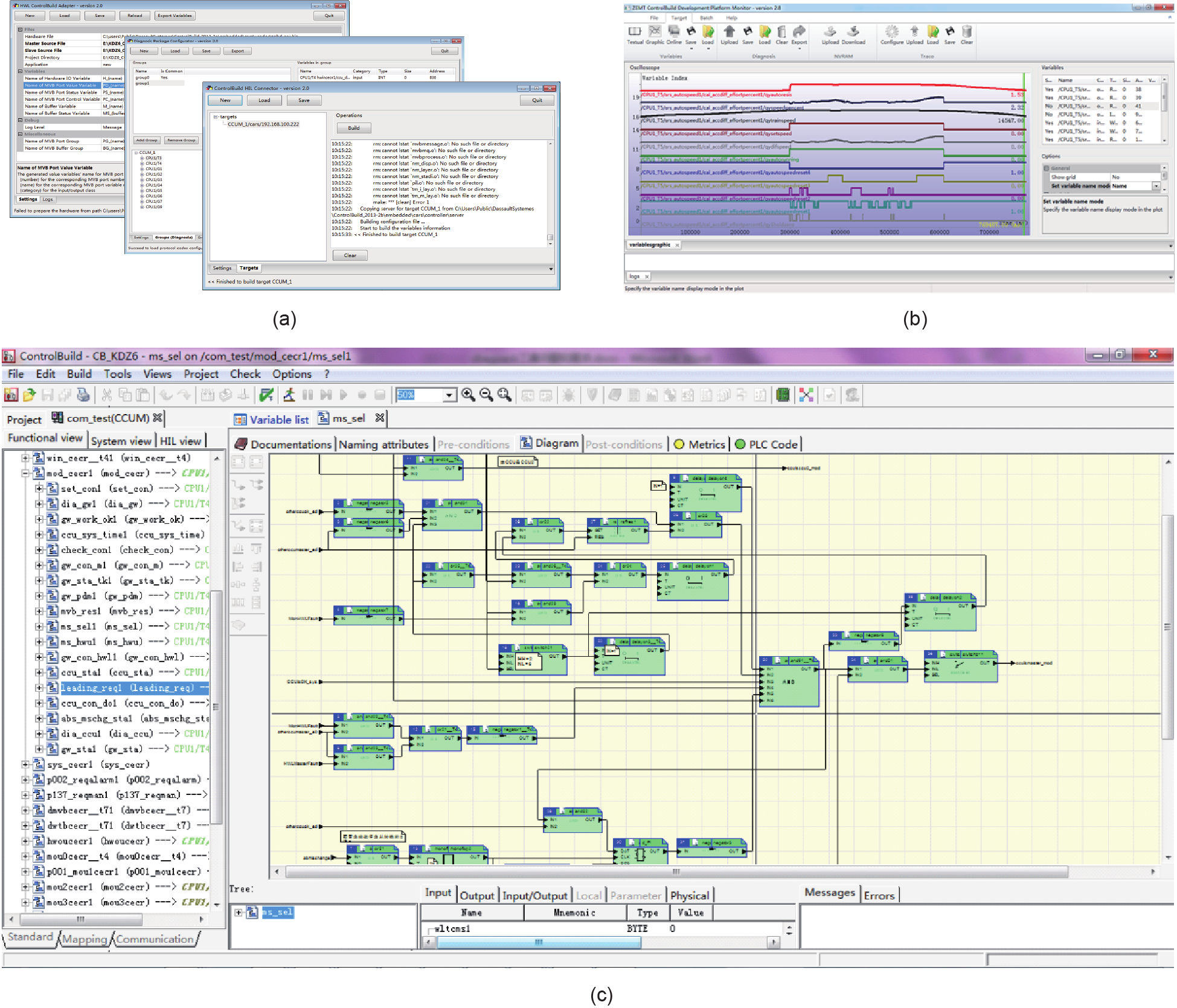
Fig. 2. The TCMS software development platform. (a) The communication interface of the hardware configuration tool; (b) the online monitoring tool; (c) the interface of the TCMS software development platform.
During the development of the TCMS design platform, the most difficult problem is that every FBD has a different running mode, according to the current system running stage (i.e., initial, start of configuration, parameter setting, and normal operation), while the project is a set of functions that are executed sequentially. If all the FBDs are divided into several segments and then compiled and linked together, the program becomes very big; it also costs a great deal of CPU resource and reduces the system running rate. To solve this problem, the macro definition method is used. When an FBD is compiled, different segments are distributed to different macros. However, only the used macros are compiled and linked to the objects’ dynamic library. All the libraries are loaded and run according to the scheduling of the control system. The benefit of the macro definition method is that it not only solves the FBD and project-running conflict problems, but also the bigger CPU resource occupation problem.
《2.2. The TCMS testing and verification bench》
2.2. The TCMS testing and verification bench
There are two kinds of TCMS testing benches: the hardware system testing bench and the software function simulation testing bench [2]. The hardware system testing bench mainly focuses on system hardware integration, communication, and I/O signal testing. It generally integrates all parts of the TCMS hardware, such as the central control unit (CCU), the HMIs, the gateway, the I/O module, the MVB repeaters, some subsystem control units, and so on. The system test software is not the real application software that runs on the train; rather, it is all the low-level software such as firmware. The operation system is the same as the real one on the train; therefore, it is possible to test almost all aspects of the system related to the hardware and communication interfaces between devices. The software function simulation testing bench includes only a part of the TCMS hardware, such as the CCU and the HMIs, but the same application software that is used on the train can be downloaded onto it. This software testing bench allows the simulation of the models for all the other TCMS devices and for their controlling devices, together with their communications, functions, and behaviors. Therefore, the software testing bench can test the control logic and diagnostic functions of the TCMS application software used on the train, although it cannot perform a complete hardware test.
Based on this evaluation of the advantages and disadvantages of these two TCMS testing benches, we propose a TCMS halfphysical testing bench development plan that integrates the advantages of both TCMS testing benches and can simultaneously test both the real hardware and the software. It can also test TCMS interfaces; communications; and functions of other subsystems, such as traction, brake, doors, heating, ventilation and air conditioning (HVAC), and so forth.
《Structure and application》
Structure and application
The TCMS half-physical testing bench consists of four main mechanical parts: the driver control panel, the vehicle cabinet, the signal-processing cabinet, and the simulation main control center [3]. The driver control panel is important because it obtains the driver’s input commands, displays device statuses, and outputs fault messages to the driver. Other important TCMS devices, such as the CCU and the HMIs, are also located here; therefore, in order to move the EMU to the laboratory and fully test its aspects, a driver control panel is built. The command input devices include a traction/brake handle, a direction switch, a pantograph raise and lower lever, the main circuit breaker close-andopen lever, the door release-and-close push buttons, and so forth. The output devices include light interfaces, a voltage meter, air pressure meters, an HMI displayer, and so forth.
The vehicle cabinet is also important on the EMU because it collects all the main electrical signals and branches them to the other subsystem cabinets. The TCMS distributed system, including the input and output MVB module devices, is located in the cabinet. The cabinet also hosts the main DC low-voltage control circuits, such as the DC power supply switches of each control device or low-voltage control loops.
The signal-processing cabinet on the testing bench is not the real device found on EMUs, but it provides the interactive simulation signals for the real devices that are in the vehicle cabinet. If there is an input module in the vehicle cabinet, there must be a simulation output device in the signal-processing cabinet that can get instructions from the simulation control center and output signals to the input module in the vehicle cabinet. In the same way, if there is an output module in the vehicle cabinet, there must be an input device in the signal-processing cabinet that can collect the signals and send them to the simulation control center.
The simulation main control center is the center of the testing bench and consists of several computers with MVB and Ethernet interfaces. The MVB interfaces are used to join the MVB units and to connect the computer to the other MVB control devices on the EMU. The Ethernet interfaces are used to connect different simulation computers and the simulation devices in the signalprocessing cabinet. Both the subsystem and the electrical circuit signals simulation software run on the simulation computers.
In general, TCMS devices can be logically divided into two parts. The first part is provided by the main integrating supplier and includes the CCU, HMIs, gateway, I/O modules, MVB repeaters, and so forth. The second part comprises the devices provided by subsystem suppliers, such as the traction system, although all of them are connected to the MVB vehicle bus. On the testing bench, some of the devices in the first part are real physical devices, while others are virtually simulated and reproduce the functional behavior of the devices. The subsystem simulation models are built on test requirements. If only the interfaces between TCMS and the subsystem require testing, a simple level control model is sufficient. If the subsystem control unit also requires testing, then all the signal states managed by the control unit must be simulated, and different model levels must be built for each subsystem. For example, the traction system is one of the most important subsystems and has many connections with TCMS functions. Therefore, a complex hardware-in-loop (HIL) traction system simulation model has been built [3]. Compared with the traction system, the brake system has fewer interfaces, so fewer signals are connected to TCMS, resulting in a simpler control model.
The application software downloaded onto the TCMS halfphysical testing bench is the same as that of a real EMU. As a result, the testing bench simulates not only the normal operation conditions of the EMU—such as operating the control lever and traction/brake commands in order to test TCMS or subsystem triggers, responses, and feedbacks—but also the EMU running behavior under abnormal conditions, such as inputting a fault trigger on the traction system and examining the consequent TCMS and subsystem responses and feedbacks.
With the TCMS half-physical testing bench, more than 85% of the software logic and diagnostic functions can be tested, and a number of software bugs can be found. In addition, high-risk tests can be performed. Compared with testing a real EMU, the integration costs and testing time are significantly reduced when using the TCMS half-physical testing bench, as are the risks. The TCMS half-physical testing bench also provides benefits for EMU LCC management and becomes a part of the corresponding process. Fig. 3 shows the structure of the TCMS half-physical testing bench, and Fig. 4 shows its physical implementation.
《Fig. 3》
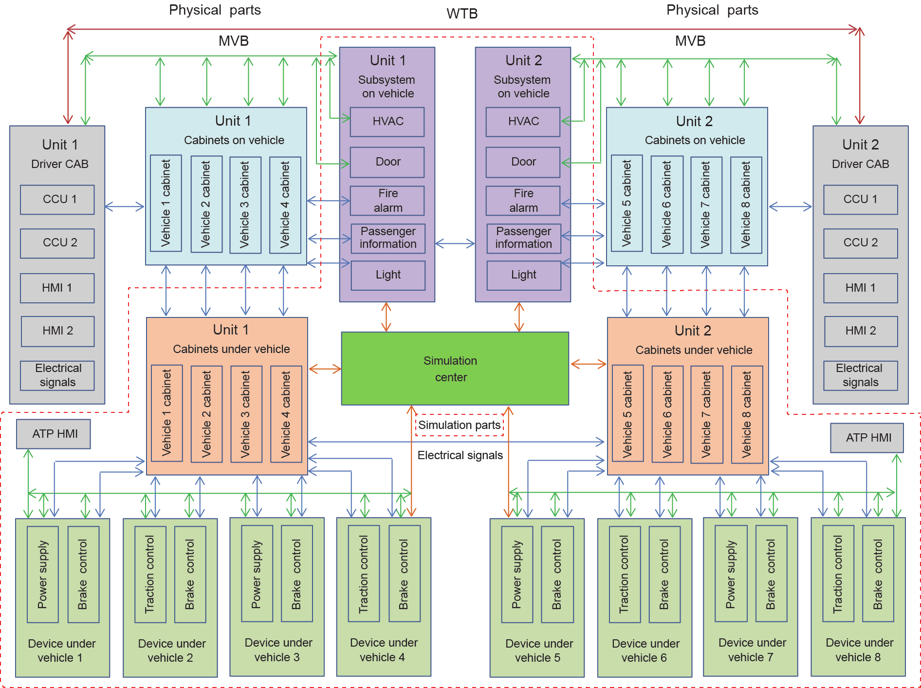
Fig. 3. The TCMS half-physical testing bench structure. CAB: cab cabinet; ATP: auto speed protection.
《Fig. 4》

Fig. 4. The TCMS half-physical testing bench. (a) The driver control panel; (b) the simulation main control center; (c) the vehicle cabinets and the signal-processing cabinets; (d) HIL test.
《3.The EMU driving simulation platform and the EMU remote data transmittal and maintenance platform》
3.The EMU driving simulation platform and the EMU remote data transmittal and maintenance platform
《3.1. The EMU driving simulation platform》
3.1. The EMU driving simulation platform
The scope of the EMU driving simulation platform is to familiarize operators with the operation specifications and routine operations, and to help them master the signals and fault codes of TCMS and connected subsystems. This platform can also be used for training for EMU emergency situations, checking the operation status, performing countermeasures, and instructing drivers how to move a train to a safe place as required.
Unlike other driver-training facilities, this platform shares simulation data with the TCMS software development platform and the TCMS testing and verification bench. It has the same control logic, diagnostic functions, and HMI display as a real EMU. Based on the EMU electrical simulation models and results, 3D operation scenery was constructed, including an EMU mechanical model and a route model, thus reducing the platform development cost and ensuring high-quality training.
The EMU driving simulation platform consists of four parts: the EMU driver operation console simulation, the EMU operation performance simulation, the EMU normal running mode and special events simulation, and the EMU fault operation mode simulation.
The EMU driver operation console simulation includes all the components that the driver can operate, including the traction/ brake handle, the pantograph control lever, the direction-setting switch, other buttons or indication lights, and HMI displays. These I/O command or feedback devices were built using 3D modeling technology. The models have a data connection with the electrical part of the simulation. When the models are operated by the driver, the electrical model and the electrical response send feedback to the mechanical part of the simulation for display.
The operation performance simulation shares the data from the TCMS software development platform and testing bench, builds the dynamic and static mechanical model for each subsystem, and transfers the relevant data to the TCMS control and testing simulation models.
The EMU normal running mode and special events simulation is constructed according to the EMU operation route, and provides the same circumstances that occur in a driver’s practical operation, such as up and down slopes, curves, track switches, and neutral sections. It also outputs scenery, such as trees, buildings, tunnels, and so forth. Changes in scenery are integrated with the EMU operation performance simulation, synchronizing the traction/brake effort and the speed data to produce an effective visual operation simulation.
The EMU fault operation mode simulation is based on a database containing the fault code categories. When the simulation model triggers a fault, the system outputs fault-safety instructions. The driver is expected to acknowledge the fault message and follow the recovery instructions to solve the problem. If the cause of the fault has been found, the fault trigger is canceled and the driver continues normally. If the fault is very serious or if the driver cannot find its cause, suitable countermeasures must be adopted, and the EMU is operated in a degraded mode.
Fig. 5 shows the structure of the EMU driving simulation platform, and Fig. 6 shows the EMU driving simulation platform itself.
《Fig. 5》
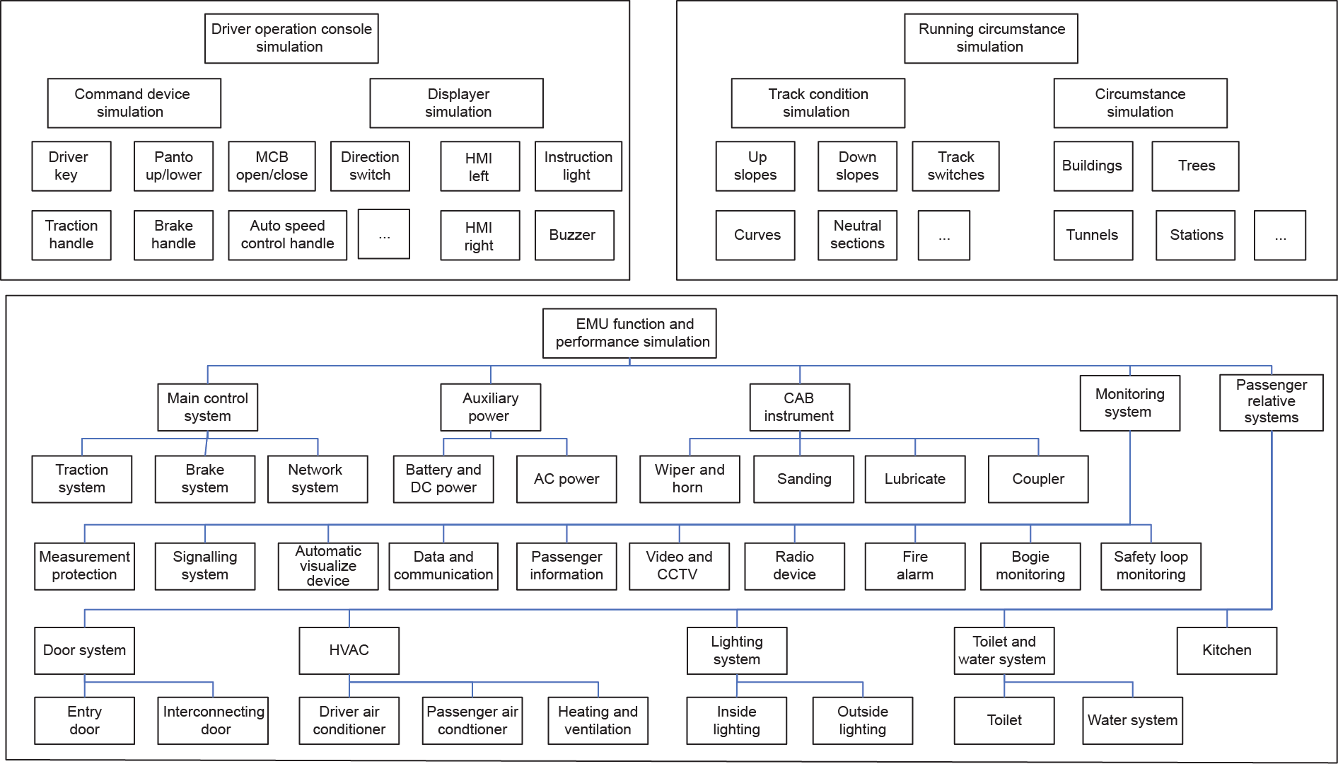
Fig. 5. The EMU driving simulation platform structure. MCB: main circuit breaker; CCTV: closed-circuit television.
《Fig. 6》

Fig. 6. The EMU driving simulation platform. (a) The train operation route design; (b) the train front view simulation; (c) the whole driving simulation platform; (d) the driver operation console.
《3.2. The EMU remote data transmittal and maintenance platform》
3.2. The EMU remote data transmittal and maintenance platform
When new types of EMU are put into operation, problems such as lack of experience, difficulties in maintenance, and a long run-in period occur one after another. The EMU remote data transmittal and maintenance platform was conceived to satisfy the following requirements: real-time monitoring of EMU status, remote technical support for emergencies, and EMU maintenance scheduling according to available fault messages and fault predictions [4].
This platform uses onboard TCMS, micro-control processing, general packet radio service (GPRS), wireless local area network (WLAN), Ethernet, and database technologies. The EMU remote data transmittal and maintenance platform is composed of two main systems: the wireless transmission device (WTD) and the ground database web-browsing system. The WTD is the main bridge of data communication between onboard and ground systems; it comprises a main computer with an MVB interface linked to the vehicle system, to GPRS, and to the WLAN interface linked to the ground site. The ground database web-browsing system is based on the client/server access mode and provides the devices’ running statuses, fault code and location tracking, operational data statistics, and inquiry functions.
The EMU is equipped with a WTD. Through MVB, all of the necessary information is collected, such as the pantograph status, main circuit breaker status, traction effort, emergency/full service braking status, global position system (GPS) data, and bearing temperatures of axles and gear boxes. Through Ethernet or another serial link method, the eventual fault event messages will be transformed when an event occurs or when the system recovers.
The data transmission and reception mechanism is the most important link between the onboard and group systems. For this reason, many optimizations of sending methods, such as the delay sending and resending mechanism, have been adopted for onboard devices. In addition, special data-processing methods, such as data reassembly and a data check mechanism, have been implemented into the ground devices. As a result of these methods, real-time, stable, consistent, and high-quality data can be received, recorded, and stored in the dedicated database. With the utilization and proper organization of the database, running data inquiry, fault code inquiry, historical data storage, and the index-searching function are easily achieved [5].
Using the ground fault codes stored in the database, the operation data are integrated, making it possible to analyze the reasons for faults and identify the location of faulty components. With the longtime accumulation of fault data, historical data, and maintenance data, various investigations can be performed, such as obtaining statistics on historical data and identifying the most likely fault occurrences; identifying the relationship between a fault event and climatic conditions; and discovering what kinds of maintenance work should be done to prevent the occurrence of certain events.
The browser/server structure is used to provide the customer with the remote data access function. Using the Internet, the customer can gain access to several functions. On the browser side, very few logic tasks need to be performed; most tasks will be developed on the server side, so a three-tier structure was formed on that side. The application of this method reduces the browserside data-elaboration loads, maintenance work and costs, and updated maintenance work schedule costs. Different users from different locations can access the common database. The structure is also beneficial in that it protects the data platform and manages the access authorities.
Fig. 7 shows the structure of the EMU remote data transmittal and maintenance platform, and Fig. 8 shows the web-browser function of EMU faults statistical analysis.
《Fig. 7》
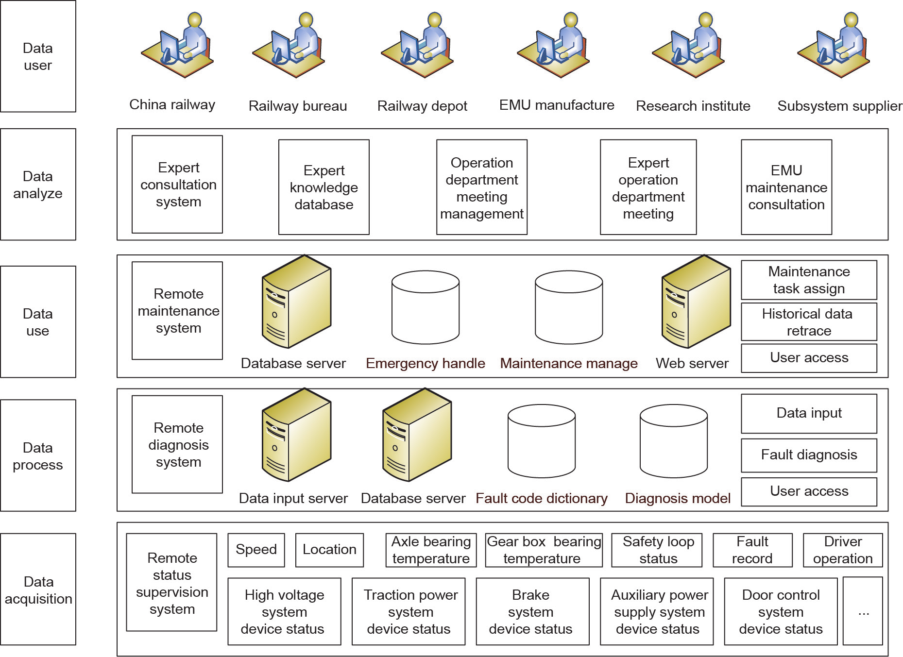
Fig. 7. The EMU remote data transmittal and maintenance platform structure.
《Fig. 8》
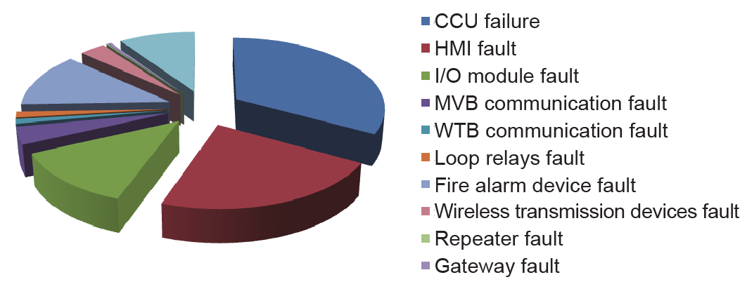
Fig. 8. The web-browser function of EMU faults statistical analysis.
《4. Results》
4. Results
The TCMS software development platform, the TCMS testing and verification bench, the EMU driving simulation platform, and the EMU remote data transmittal and maintenance platform have been widely used in the China high-speed railway. The TCMS software development platform and the TCMS testing and verification bench have been used in the development and testing stage for a new type of EMU, and before a new line was put into the operational stage. These two platforms played an important role in hardware and software integration testing, TCMS and subsystem interface and function testing, field fault simulation, fault reason analysis, and field fault solution validation. The EMU driving simulation platform has been used to train operators by familiarizing them with typical operational circumstances; explaining operation specifications and routine operations; and helping them to know the signals, fault codes, and emergency procedures for the EMU. The EMU remote data transmittal and maintenance platform provides excellent technical support for EMU operation, safety risk prevention, and controls. Fault message information helps the depot workshop to properly assign maintenance work, and helps maintenance engineers to prepare maintenance materials and tools. This platform enables fast response and highquality maintenance.
Using these platforms and benches, an EMU can be supervised from its design stage to its maintenance stage. All these platforms and benches make up the EMU LCC system. Each platform or bench is part of the EMU LCC management and becomes an important part of the EMU LCC management system. In the near future, each platform or bench will be improved to become more useful and more integrated. An EMU driving simulation platform will also be developed for the new type of EMU with the TCMS software development platform. The driving simulation platform can also be used for new EMU market development. The EMU remote data transmittal and maintenance platform will be improved with historical data accumulation, and an EMU health management and fault-prediction function will be realized gradually. With progress in science and technology, high-speed EMUs will become safer and more available, and the EMU LCC will decrease.
《Compliance with ethics guidelines》
Compliance with ethics guidelines
Hongwei Zhao, Zhiping Huang, and Ying Mei declare that they have no conflict of interest or financial conflicts to disclose.


 京公网安备 11010502051620号


