

《1.Introduction》
1.Introduction
Renewable-based electrical supply systems are intermittent by nature, and have a great impact on the stability and reliability of the electricity grid. Energy storage technologies are required as more renewables come online; of these technologies, hydropower pumped storage is the only commercially available grid-scale technology at present. In this technology, water is pumped to an upper reservoir if the energy supply is higher than the demand, and is then used to generate electricity when the demand is higher than the supply. In addition to load-leveling, this technology benefits the grid with grid frequency regulation and spinning reserves [1].
Although the earliest pumped storage power (PSP) stations were built in the Alpine region in the 1890s, the first PSP station in China appeared some 80 years later, in the form of small-scale mixed PSP stations in Gangnan and Miyun, with a total capacity of 11 MW and 22 MW, respectively [2]. Starting in the 1990s, the construction of large-scale PSP stations in China entered a period of fast development in response to the increasing demand caused by the highspeed development of the national economy. More and more PSP stations with a total capacity over 1000 MW are being constructed.
As the hydraulic components responsible for the energy transformation between the generator/motor and water, reversible pump-turbines, which work in both turbine and pump modes, have replaced sets of separate turbines and pumps since the 1960s, due to their relatively compact sizes. Considering the flow directions at the inlet and outlet, pump-turbines can be categorized as axial flow, diagonal flow, or Francis pump-turbines, among others. Since Francis pump-turbines (henceforth referred to as pump-turbines for simplicity) have the widest range of working head, most modern designs fall into this category [3]. In order to reduce manufacturing and construction costs, and increase the unit hydraulic efficiencies, more pump-turbines are adopting a larger unit capacity and higher heads. Fig. 1 shows the unit capacity and head of pump-turbines in built PSP stations in China over time. Most unit capacities are now over 300 MW, and the highest head is over 600 m. The heads of several other PSP stations under construction or planning reach 600–700 m, such as those of Yangjiang, Jixi, Pingjiang, and Wulongshan.
《Fig. 1》

Fig. 1. Unit capacity and head of pump-turbines in built PSP stations in China over time. Unit capacities of pump-turbines are comparable to the areas of the circles.
Hydraulic instabilities such as pressure fluctuations are more severe with higher working heads, and may induce mechanical vibrations through fluid-structure interaction [4] and, in extreme cases, premature mechanical failures [5]. Certain flow characteristics such as vortices in the draft tube and turbine runner, and the rotor-stator interaction (RSI), are known for promoting large pressure fluctuations. It should also be noted that differences exist in the working head of pump-turbines between the turbine and pump modes, in order to account for the hydraulic losses in pipelines. The design of a pump-turbine first needs to guarantee the pump performance. Hence, pump-turbines share more similarity in shape with centrifugal pumps than with Francis turbines. Pump-turbines with higher heads, which correspond to lower values of specific speed (ns), that is,

where n, Q, and H are the runner rotating speed, the volumetric flow rate, and the hydraulic head, respectively, possess more prolonged flow channels. They are more prone to so-called S-shaped characteristics and positive slopes on performance curves in turbine and pump modes, respectively, which promote operational instabilities [6].
This paper systematically summarizes the hydraulic instabilities and performance characteristics that promote operational instabilities in pump-turbines in China, and illustrates the related flow mechanisms through a literature review. Precautions and countermeasures against these instabilities are also presented.
《2.Hydraulic instabilities: Pressure fluctuations》
2.Hydraulic instabilities: Pressure fluctuations
Hydraulic instability problems have been reported in several PSP stations in China, along with their effects on the dynamic behavior of parameters, such as shaft line or head cover vibrations, shaft displacement, and operating difficulties. A schematic of the hydraulic components of a pump-turbine is shown in Fig. 2 [4] for reference.
《Fig. 2》

Fig. 2. Schematic of the hydraulic components of a pump-turbine. (Adapted from Ref. [4])
《2.1. Guangzhou I》
2.1. Guangzhou I
The Guangzhou I PSP station has four pump-turbines, each with 300 MW unit capacity. The numbers of runner blades, guide vanes, and stay vanes are 7, 20, and 20, respectively.
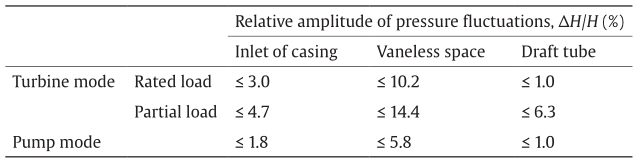
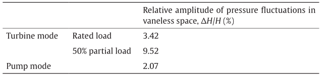
During the first year of operation, it was reported that the pressure fluctuations in the vaneless space and the draft tube had high amplitudes when running at excessive partial load (≤ 40% rated load) in turbine mode (Table 1) [7]. The main frequencies of pressure fluctuations in the vaneless space and the draft tube were the blade passing frequency (BPF)—which is equal to the number of runner blades times the runner rotational frequency—and near the rotational frequency, respectively. While in pump mode, the relative amplitude of pressure fluctuations in the vaneless space was in the range of 5%–6%. It reached 7.4% when H < 517 m and Q > 59 m3·s−1. In the startup of the pump mode, the amplitude of pressure fluctuations reached 51.6% [7]. According to Ref. [8], excessive throws (~800 μm) appeared in the upper and lower guide bearings in the No. 4 pump-turbine unit in the Guangzhou I PSP station, both in turbine mode and in pump mode, due to the uneven circumferential distribution of clearance in the bearings and to misalignment in the shaft system. It was also reported that in the first month after the commissioning of the Guangzhou I PSP station, 16 failures (out of 45) appeared in the startup, such as being unable to synchronize to the grid; some of these failures were caused by excessive pressure fluctuations [9].
《Table 1》
Table 1 Pressure fluctuations in the Guangzhou I PSP station (data from Ref. [7]).
《2.2. Shisanling》
2.2. Shisanling
The Shisanling PSP station has four pump-turbines, each with 200 MW unit capacity. The numbers of runner blades, guide vanes, and stay vanes are 7, 16, and 16, respectively.
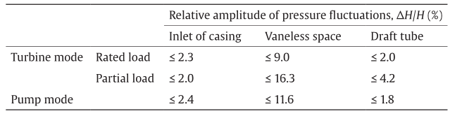
Compared with the Guangzhou I PSP station, the pressure fluctuations in the vaneless space had higher amplitude at the Shisanling PSP station (Table 1 and Table 2) [7]. According to Ref. [7], preliminary research indicated that these pressure fluctuations were related to the combination of the numbers of runner blades and guide vanes. A larger vibration could be excited in the vaneless gap between 7 runner blades and 16 guide vanes. The throw of the turbine guide bearing was large since the commencement of the No. 1 unit in 1995, being 0.2 mm at the rated working condition, and reaching a maximum value of 0.38 mm. The high throw at different locations resulted in a large unit centrifugal inertia force and a stronger structure vibration. The temperature of the guide bearing increased to a dangerous value due to the vibration. After adjustment of the bearing clearance, the throw of the turbine guide bearing was reduced to 0.14 mm at the rated condition, and to a maximum of 0.24 mm [10]. It was also reported that since the commencement of the station, synchronization failure (i.e., the unit cannot synchronize to the grid for more than 10 min after startup) occurred in every pump-turbine unit in the Shisanling PSP station every year [11].
《Table 2》
Table 2 Pressure fluctuations in the Shisanling PSP station (data from Ref. [7]).
《2.3. Guangzhou II》
2.3. Guangzhou II
The Guangzhou II PSP station has four pump-turbines, each with 300 MW unit capacity. The numbers of runner blades, guide vanes, and stay vanes are 7, 20, and 20, respectively.
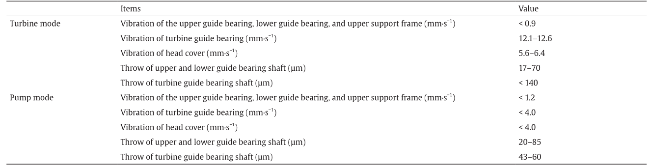
Table 3 [12] shows the vibration and the throw of the unit during field tests in 2001. The results show that the vibration of the upper guide bearing, lower guide bearing, and upper support frame was small in both turbine and pump modes, while the vibration of the turbine guide bearing and of the head cover was much larger. In turbine mode, the vibration velocity reached up to about 12 mm·s−1 in the turbine guide bearing and up to about 6 mm·s−1 in the head cover [12]. It was also reported that during 2002‒2004, the pump-turbines experienced a number of abnormal shut-downs due to non-synchronization of the guide vanes [13].
《Table 3》
Table 3 Vibrations and throws in the Guangzhou II PSP station (data from Ref. [12]).
《2.4. Tianhuangping》
2.4. Tianhuangping
The Tianhuangping PSP station has six pump-turbines, each with 300 MW unit capacity. The numbers of runner blades, guide vanes, and stay vanes are 9, 26, and 26, respectively.
As shown in Table 4 [14], the pressure fluctuations in the vaneless space were high in turbine mode (highest amplitude over 50%). Table 5 [14] shows the vibrations and throws in the Tianhuangping PSP station.
《Table 4》
Table 4 Pressure fluctuations during off-design turbine conditions in the Tianhuangping PSP station (data from Ref. [14]).

P1, P2: between runner and bottom ring; P3, P4: between runner and head cover; P5, P6: vaneless space.
《Table 5》
Table 5 Vibrations and throws in the Tianhuangping PSP station (data from Ref. [14]).

During the test run of the first unit of the Tianhuangping PSP station, the throw of every guide bearing and the vibration of the frame in turbine mode were large, at H < 526 m (designed head). The unit was unable to operate stably at the designed rotational speed of 500 r·min−1. Pressure fluctuations were also high in the vaneless space [15,16]. In April 2002, the occurrence of an abnormal noise was reported when the No. 1 unit of the Tianhuangping PSP station stopped from pump mode. It was believed that the late switch-off of the main brake and small opening (4%) of the guide vanes resulted in a zero flow rate in pump mode, which induced high-amplitude pressure fluctuations in the vaneless space [17]. On 4 January 2003, unit lifting due to upward thrust occurred during load increase in the No. 2 unit of the Tianhuangping PSP station. It stabilized after 10 min. Pressure in the upper labyrinth ring fluctuated up to 0.15 MPa, and the vibration of the head cover reached 8.4 mm·s−1. It was suspected that this may have been due to the large pressure fluctuations in the draft tube in the generating mode [18].
《2.5. Yixing》
2.5. Yixing
The Yixing PSP station has four pump-turbines, each with 250 MW unit capacity. The numbers of runner blades, guide vanes, and stay vanes are 9, 26, and 26, respectively.
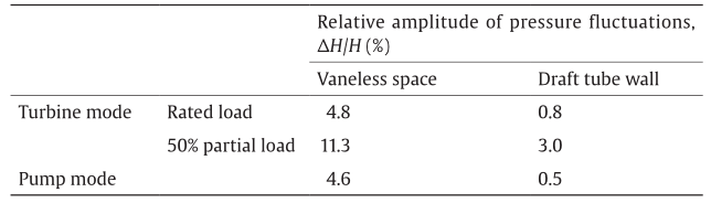
The pressure fluctuations in the Yixing PSP station are relatively lower than those in some other stations (Table 6) [19]. The relative amplitude in the vaneless space at 50% partial load in turbine mode is 4.2%. The maximum vibration of the head cover is 0.82 mm·s−1, and the throw of the turbine guide vanes is 71.18 μm [19].
《Table 6》
Table 6 Pressure fluctuations in the Yixing PSP station (data from Ref. [19]).

An abnormal sound, as well as the non-synchronization of the guide vanes, occurred during the over-speed test of the No. 3 unit of the Yixing PSP station. It was shown that the pressure in the draft tube increased rapidly while the pressure in the spiral casing dropped, forming a negative water hammer, during the transition of the unit from reverse pump mode into turbine break condition. This problem was solved by reducing the closing speed of the guide vanes, according to Ref. [20]. Strong guide vane vibrations were experienced during the commissioning of pump starting, pump closing, and turbine mode in the over-speed and turbine trip tests of the No. 1 unit of the Yixing pump-turbine. This issue was corrected by making adjustments to the guide vane closing sequence (during turbine over-speed and turbine trip), or by opening the circuit breaker at a higher power (during pump closing) [21].
《2.6. Xilongchi》
2.6. Xilongchi
The Xilongchi PSP station has four pump-turbines, each with 300 MW unit capacity. The numbers of runner blades, guide vanes, and stay vanes are 7, 20, and 20, respectively. The pressure fluctuations in the pump-turbines are shown in Table 7.
《Table 7》
Table 7 Pressure fluctuations in the Xilongchi PSP station.
《2.7. Baoquan》
2.7. Baoquan
The Baoquan PSP station has four pump-turbines, each with 300 MW unit capacity. The numbers of runner blades, guide vanes, and stay vanes are 9, 20, and 20, respectively. The pressure fluctuations in the pump-turbines are shown in Table 8.
《Table 8》
Table 8 Pressure fluctuations in the Baoquan PSP station.
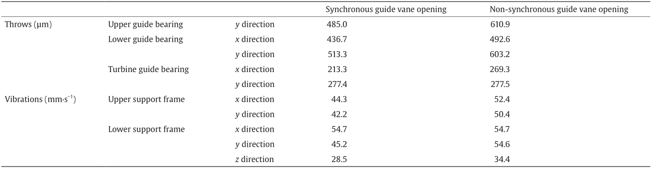
As shown in Table 9, with non-synchronous guide vanes opening using misaligned guide vanes (MGVs), the flow in the vaneless space became non-uniform in different guide vane channels, increasing the vibrations and throws of the unit.
《Table 9》
Table 9 Throws and vibrations in the Baoquan PSP station.
《2.8. Huizhou》
2.8. Huizhou
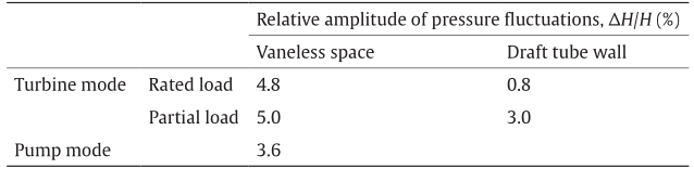
The Huizhou PSP station has eight pump-turbines, each with 300 MW unit capacity. The numbers of runner blades, guide vanes, and stay vanes are 9, 20, and 20, respectively. Pressure fluctuations, throws and vibrations in the Huizhou PSP station are listed in Table 10 and Table 11.
《Table 10》
Table 10 Pressure fluctuations in the Huizhou PSP station.
《Table 11》
Table 11 Throws and vibrations in the Huizhou PSP station.
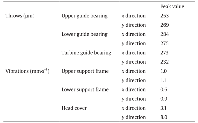
The vibrations of the unit exceeded the limit under the conditions of rated speed and no load, due to the unsynchronized opening of the guide vanes. Using MGVs induced especially large vibrations of the servomotor, resulting in fractures in the connecting bolts of the servomotor in the unit test. Improvement was made by adding two extra MGVs to reduce the stress on a single guide vane [22].
《2.9. Summary》
2.9. Summary
With the data collection above, it can be seen that the pressure fluctuations in the vaneless space between the runner blades and the guide vanes have the maximum amplitudes in pump-turbines. It has been established that these characteristics of pressure fluctuations are promoted by the effect of RSI, including the potential flow (inviscid) interaction and the wake (viscous) interaction [4].
Tanaka [23] proposed a model to explain the diametrical vibration modes in high-head pump-turbines induced by RSI. When the runner blades pass across the wakes of the vanes, the flow interference induces vibrations/pressure fluctuations in the runner with frequencies of n·Zg·fn when observed from the rotating coordinates, and with frequencies of m·Zr·fn (where Zr·fn is the BPF) when observed from stationary coordinates, where Zg is the number of guide vanes, Zr is the number of runner blades, fn is the rotational frequency of the runner, and m and n are arbitrary integers. The vibration mode with k diametrical nodes is calculated by the equation n·Zg ± k = m·Zr. An example of RSI with Zg = 20 and Zr = 6 is shown in Fig. 3 [23], which includes a schematic of the phase lag of the interferences and the different vibration modes in terms of the number of diametrical nodes.
《Fig. 3》

Fig. 3. Vibrations in the vaneless space due to RSI in the pump-turbine [23]. (a) Hydraulic interference between runner blades and guide vanes; (b) vibration modes with k diametrical nodes.
Ref. [4] summarizes the major parameters of pump-turbines that influence pressure fluctuations. Pump-turbines working under off-design conditions have pressure fluctuations of larger amplitudes, due to the flow separations in the runner/guide vane channels. It is also reasonable that the distance of the vaneless gap is another determinant of the pressure fluctuations. An optimum distance of the vaneless gap exists, in terms of the lowest amplitude of pressure fluctuations in pump mode, according to Ref. [24]. Another study showed that a smaller vaneless gap caused higher pressure fluctuations in the vaneless gap in pump mode, and lower pressure fluctuations in turbine mode [25]. Regarding the cavitation condition, Ref. [24] reported an increase of 30%–40% in the amplitude of the pressure fluctuations at the critical cavitation coefficient number, compared with the non-cavitating operating points. By experimentally comparing three different pump-turbine models, it was shown that after increasing the guide vanes’ height by 40%, the amplitude of the pressure fluctuations in the vaneless space was reduced by 20%–30%, whereas the thickness of the guide vanes had little influence on pressure fluctuations [26]. Research also showed that the application of twisted runner blades helped to reduce the pressure fluctuations [27].
《3.Performance characteristics promoting operational instabilities: S-shaped characteristics and positive slopes》
3.Performance characteristics promoting operational instabilities: S-shaped characteristics and positive slopes
In a pumping system, two types of instability can be described, in terms of the transient response to an initial perturbation: static instabilities, which refer to a continuous increase in the amplitude of the perturbation; and dynamic instabilities, which refer to oscillation of the continually increasing amplitude of the perturbation [28]. The static instability of the system is associated with a divergence from the initial operating point, and can be characterized by the (quasi-)steady-state performance characteristics. Static stability is a necessary but insufficient condition for dynamic stability. Although this criterion is less rigorous than the dynamic instability, it provides a more practical standard to distinguish between instabilities in engineering applications.
 denotes the discharge factor,
 denotes the speed factor, and T ED= T/(ρD3E) denotes the torque factor (where E is the specific hydraulic energy of the unit and T is the torque) [29]. Characteristic curves in terms of unit flow rate and speed, Q11 ~ n11, are also seen in the literature [6]. In pump mode, the slope of the EnD ~ QnD characteristic can be positive in a limited range of discharge (Fig. 4(b)) [29], in which EnD = E/(n 2D2 ) denotes the energy coefficient, and QnD = Q/(ND3 ) denotes the discharge coefficient. Characteristic curves in terms of hydraulic head and flow rate, H ~ Q, are also seen in the literature.
《Fig. 4》

Fig. 4. Performance characteristics of pump-turbines that promote operational instabilities. (a) S-shaped characteristics; (b) positive slope. (Adapted from Ref. [29])
 is the unit flow rate,
  is the unit speed, and T11 = T/(ΡD3 H) is the unit torque. For example, You et al. [30] reported these instabilities during trial operations at the Tianhuangping power station under a low water head. Fig. 5(b) [3] illustrates an extreme case during pump startup, where the pipeline characteristics pass through the positive slope zones at the guide vane opening from 40% to 50%. Instead of passing from A → B → C → D → F, as the operation is intended to proceed, it may pass through A → B → C → D → E, because of the existence of the positive slopes.
《Fig. 5》

Fig. 5. Operational instabilities in the transient processes of pump-turbines. (a) Turbine startup and load rejection [6]; (b) pump startup (adapted from Ref. [3]).
A detailed discussion of the flow mechanism of the S-shaped characteristics can be found in Ref. [6]. Through experimental and computation fluid dynamics studies, complex flow features in the region of S-shaped characteristics in the pump-turbines, such as, backflow at the runner inlet, stationary vortex formation, and rotating stall in the vaneless space, have been identified, especially under speed no-load conditions. Similarly, secondary flows [31], rotating stall in vaneless space and guide vane channels [32–46], and impeller inlet pre-rotation [34] are believed to form the main flow mechanism of the positive slopes.
Considering the instabilities promoted by these two performance characteristics, safety margins are usually contractually prescribed for the designers. Fig. 6(a) [6] illustrates the derivation of the safety margin for the S-shaped characteristics. First, model tests are conducted with increments of guide vane openings of no more than 1°.The slope of the Q11 ~ n11 curves, with constant guide vane opening at the intersections with the runaway curve, increases with increasing guide vane opening. A critical point is defined at which Q11/n11 ~ 0, or T11/n11 ~ 0 on T11 ~ n11 curves [47,48]. The safety margin on the head is then calculated as the difference between the head at the critical point and at the unit minimum head within the allowable frequency range of the power grid (50.5 Hz in Fig. 6(a)). Minimum values of this margin have been suggested for engineering practice (40 m in Ref. [48] and 20 m in Ref. [49]). Regarding the safety margin for the positive slopes, although positive slopes can exist on multiple pump performance curves with constant guide vane openings, the pump performance curve at the highest pump head is typically considered to assess the safety margin. The pump performance curve and the equivalent pipeline characteristics in the operational head range of the pump-turbine are shown in Fig. 6(b) [50], in the case where the frequency of the power grid oscillates in the range of (f − Δf1, f + Δf2) [50]. The safety margin on the head is specified as the ratio against the maximum working head Hsm/Hmax. Ref. [51] suggests a value of no less than 2% in China, corresponding to a 49.8–50.5 Hz power grid frequency oscillation range. Different values have been assigned in model acceptance tests with different PSP stations in China, such as 3% for Baoquan [52] and Xiangshuijian [53], and 4% for Heimifeng[54].
《Fig. 6》

Fig. 6. Safety margins of pump-turbines. (a) S-shaped characteristics [6]; (b) positive slope (adapted from Ref. [50]).
It is shown that the design of the pump-turbine runner has a great influence on the performance characteristics. For example, a parametric study showed that regarding turbine performance, in order to make a pump-turbine more stable, one should increase the radius of curvature on the pressure side of the leading edge in turbine mode, decrease the inlet radius, increase the inlet blade angle, or increase the length of the blade [55]. By investigating three model pump-turbines with different guide vane heights and runner vane thicknesses, it was discovered that when the runner vane thickness was increased by 5%, decreases of 5% were achieved in the corresponding discharges of the “saddle” peak, and the best efficiency point on the H ~ Q curve was achieved [26].
In dealing with the difficulties in synchronization with the power grid promoted by the S-shaped characteristics, it should be noted that a technique applying MGVs has been adopted in a number of PSP stations. This technique was first introduced on COO II (Belgium) pump-turbines [56], and has been applied in the Tianhuangping [57] and Yixing [58] PSP stations in China. A large number of research studies have been carried out on the flow mechanism, the influence on the pressure fluctuations, and the optimization of the application of MGVs. Readers are encouraged to refer to Ref. [6] for details.
《4.Conclusions》
4.Conclusions
Pump-turbines with higher head and larger capacity are more prone to hydraulic instabilities, such as pressure fluctuations, and to performance characteristics that promote operational instabilities, such as S-shaped characteristics and positive slopes in turbine and pump modes, respectively. This paper summarizes the hydraulic instabilities encountered in pump-turbine operations in PSP stations in China. The most detrimental pressure fluctuations in pumpturbines, that is, pressure fluctuations in the vaneless space, have been identified. An analytical method of the major frequencies that considers the main flow mechanism has been presented. Along with a description of pump-turbine operations in China, an introduction to unstable performance characteristics has been provided, which included the instability criterion, definitions, induced instabilities during transient processes, the flow mechanism, precautions, and means of countering such issues.
《Acknowledgements》
Acknowledgements
The authors would like to thank the National Natural Science Foundation of China (51476083) for its financial support.
《Compliance with ethics guidelines》
Compliance with ethics guidelines
Zhigang Zuo and Shuhong Liu declare that they have no conflict of interest or financial conflicts to disclose.
Nomenclature
D Diameter of runner
E Specific hydraulic energy
EnD Energy coefficient, E nD = E/(n2D2 )
fn Rotational frequency of the runner
H Hydraulic head
Hsm Safety margin on head
k Number of diametrical nodes
m Arbitrary integer
n Runner rotating speed, arbitrary integer
n11 Unit speed, 
nED Speed factor, 
ns Specific speed,
Q Volumetric flow rate
Q11 Unit flow rate,
QED Discharge factor, 
QnD Discharge coefficient, 
T Torque
T11 Unit torque, 
T ED Torque factor, 
Zg Number of guide vanes
Zr Number of runner blades
ΔH Amplitude of pressure fluctuations


 京公网安备 11010502051620号


