

《1. Introduction》
1. Introduction
Steel box decks are very prevalent in the construction of longspan bridges, and especially of those built in strong-wind-prone regions, because of their good performance against flutter. However, they often suffer from various degrees of vortex-induced vibrations (VIVs) [1–4], which may cause driving comfort and safety problems or fatigue problem of bridge structural members. Therefore, accurate predictions of VIV responses are very important to wind-resistant designs of long-span steel bridges, and correct or reliable mathematical models of vortex-induced forces (VIFs) are very necessary to fulfill this end.
It is very easy for VIV to occur at low wind speeds on long-span bridges, and VIV is always self-limiting in amplitude because of the nonlinearities of VIFs. Although the surface mechanism of the VIF nonlinearity may intuitively be attributed to the continuous change of the transient wind attack angle, and thus to the aerodynamic shape of the bridge deck relative to the direction of incident wind during the vibration, the inherent mechanism is actually rather complicated and has not been ascertained thoroughly. Scanlan’s empirical nonlinear model for VIF is the most famous model of its type and is frequently used in research on bridge VIV [5,6]. This model uses a nonlinear item of aerodynamic damping force, expressed as a product function of the velocity and displacement square of the vibration, to attempt to reproduce the self-limiting behavior of VIV. Larsen [7] revised Scanlan’s empirical nonlinear model into a generalized empirical nonlinear model by introducing a shape parameter to adjust the nonlinear order of aerodynamic damping. However, it was found that Scanlan’s and Larson’s empirical nonlinear models of VIF are inadequate to depict the nonlinear vertical VIF acting on a closed box deck and on a centrally slotted box deck [8,9].
As mentioned above, an intuitive cause of the VIF nonlinearity is the continuous change of the transient wind attack angle during deck vibration. Therefore, for the vertical VIV, the vertical velocity of the deck motion should be included in the auto variables of the nonlinear aerodynamic damping coefficient in the mathematical model of vertical VIF; however, it was unreasonably discarded in most empirical models of VIF, including Scanlan’s and Larson’s models. Here, we present new nonlinear models for the vertical VIFs on different types of box deck, based on a series of wind-tunnel tests of a large-scale spring-suspended sectional model with simultaneous measurements of dynamic force and displacement response [8–10]. It was proven that these new models can depict the measured nonlinear vertical VIFs on bridge box decks well, and can predict the vertical VIV responses with sufficient accuracy. However, the presented new VIF models contain different nonlinear components for different types of bridge deck. The corresponding identification of the model parameters requires the synchronous measurement of the time history signals of VIF on, and the dynamic displacement of, oscillating sectional models. This measurement is more complicated and difficult than conventional wind-tunnel tests, which only have convenient measurements of dynamic displacement.
In view of this difficulty, we propose a simplified nonlinear mathematical model of the vertical VIF for easy practical application by reducing the requirements for the techniques and instruments of the wind-tunnel test for parameter identification. This simplified model, which is introduced in this paper, only requires the convenient measurements of the dynamic displacements of a sectional model for parameter identification, and seems to be applicable to different types of bridge decks, including at least the three types of box decks studied in this paper.
《2. Wind-tunnel tests of synchronous measurements of vertical VIFs and dynamic displacements》
2. Wind-tunnel tests of synchronous measurements of vertical VIFs and dynamic displacements
《2.1. Three tested typical box decks》
2.1. Three tested typical box decks
Xiangshan Harbor Bridge in Ningbo of Zhejiang Province is a cable-stayed bridge with a main span of 688 m and a fully closed box deck, as shown in Fig. 1(a). Xihoumen Bridge in Zhoushan of Zhejiang Province is a suspension bridge with a main span of 1650 m and a centrally slotted box deck, as shown in Fig. 1(b). Old Haihe Bridge in Tanggu of Tianjin is a single-tower cablestayed bridge with a main span of 310 m and a semi-closed box deck, as shown in Fig. 1(c). These three typical box decks were taken as the research objects of this study.
《Fig. 1》

Fig. 1. Deck cross-sections of three typical bridges (unit: cm). (a) Fully closed box deck; (b) centrally slotted box deck; (c) semi-closed box deck.
《2.2. Wind-tunnel and test facilities and sectional models》
2.2. Wind-tunnel and test facilities and sectional models
Spring-suspended large-scale sectional model tests for synchronous measurements of the VIFs on, and dynamic displacements of, the three typical bridge decks were carried out in a TJ-3 wind tunnel at Tongji University. This wind tunnel is a boundary layer wind tunnel with a vertical closed circuit and a closed testing section that is 15 m in width, 2 m in height, and 14 m in length. The range of wind speed is 1.0–17.6 m ·s-1. As an example, Fig. 2 shows the schematic diagraph of the large-scale sectional model test of the semi-closed box deck. The sectional model was suspended between two supporting frames in the wind tunnel, with eight helical springs fixed through two suspending arms at the two ends of the model. To reduce the disturbance of the frames in the wind flow, the two supporting frames were wrapped with fairings, constituting an internal supporting and a fairing wall system. The two supporting and fairing walls were 3.5 m long in the downwind direction and were separated at a net distance of 3.63 m in the crosswind direction. The windward ends of the walls had an arc shape in order to improve the flow quality in the testing area between the two walls. The measurement results show that in the case without model, the non-uniformity of the mean wind speeds is lower than 2%, both the longitudinal and vertical turbulent intensities are lower than 2%, and both the wind inclination and the yaw angles approach 0°.
《Fig. 2》

Fig. 2. (a) Schematic diagraph of synchronous measurements of dynamic force and displacement on a spring-suspended sectional model; (b) photograph of the model installed in the TJ-3 wind tunnel.
Each of the deck sectional models was comprised of an internal rigid metal framework and an external coat system. The latter was divided into one middle segment coat and two side segment coats for the fully closed and semi-closed box decks, and only the middle one was used for the force measured, whereas a whole measurement segment coat was used for the centrally slotted box deck. The model coat was made of a frame system of rectangular thin-wall stainless tubules covered by light, thin aviation boards with an inner liner of high-density foam. The purpose of using this somewhat complex configuration for the model coat was to ensure that it was stiff enough, and thus avoid any perceivable local vibration of the coat, while reducing its mass and inertia force as much as possible. The measurement segment of the coat was supported on the internal rigid metal framework by means of four singlecomponent force balances inside the deck model, as shown in Fig. 3. Thus, only the dynamic force on the measured coat segment was transferred to the force balances, and the inertia force on the force balances was significantly reduced. Details on the model configuration and the balance installation are available in Refs. [8–10]. The major parameters of the sectional models are listed in Table 1.
《Fig. 3》
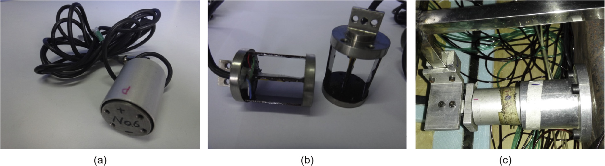
Fig. 3. Single-component force balance used in the wind-tunnel tests. (a) Appearance; (b) internal structures; (c) installation in models.
《 Table 1》
Table 1 Major parameters of sectional models.

a Widths without/with the two side cantilever split plates, respectively, including the central slot width of 0.3 m.
b Including non-wind-induced additional mass.
c Including non-wind-induced additional damping ratio; the actual damping ratios of the sectional model system are dependent on vibration amplitude.
The length scale of the model was set to 1/20, 1/20, and 1/15, respectively, for the three tests, so that the models had enough internal net space to facilitate the installation of the force balances inside the models and to maintain a non-contact state between the measured coat segment and the internal rigid metal framework. The depths of the deck models were thus 0.175 m, 0.175 m, and 0.189 m, respectively. The corresponding blockage ratios reached about 13.9%, 8.8%, and 9.5%, respectively, because of the limitation of the testing section height of the wind tunnel. Although this level of blockage ratios may result in some errors in the tested values of VIV responses, VIFs, and VIF model parameters, the general nonlinear relations between VIFs and the deck motion responses obtained by analyzing the test results should not significantly deviate from the real ones, and should be believable. However, for such a wide sectional model, the non-wind-induced aeroelastic force must be taken into account when extracting the VIFs from the total dynamic force measured by the force balances. The approach for identifying the non-wind-induced additional mass and damping coefficient of the model systems, which are used to describe the non-wind-induced aeroelastic force, can be found in Refs. [8,9].
《2.3. Measured displacement responses of VIVs》
2.3. Measured displacement responses of VIVs
The dynamic displacement responses of the sectional models were measured with laser displacement sensors. It was found that the most significant VIV occurred at the wind attack angles (θ) of 5° for the fully closed box deck, and 0° for both the centrally slotted box deck and the semi-closed box deck; therefore, only the corresponding test results are discussed here, due to the space limitation. The stable amplitudes of the vertical VIV displacement in the look-in ranges of the wind speed are shown in Fig. 4(a)–(c), respectively, for the fully closed box deck at h = 5°, and for both the centrally slotted box deck and the semi-closed box deck at θ = 0°.
《Fig. 4》

Fig. 4. Stable amplitudes of the vertical VIV displacement of sectional models. (a) Fully closed box deck (θ = 5°); (b) centrally slotted box deck ( θ= 0°); (c) semi-closed box deck (θ= 0°). U: the wind speed; n: the nominal total damping ratio of model system at zero wind speed; f: the vertical frequency of model; Ay: the stable amplitude of VIV displacement; Aη: the dimensionless stable amplitude of VIV displacement; D: the deck depth.
For the fully closed box deck under wind conditions with an attack angle of 5°, it can be found that the lock-in ranges of the wind speed are 6.44–10.06 m·s-1 and 6.69–9.90 m·s-1, respectively, for the damping ratios of 0.55% and 0.73%. The maximal response of the vertical VIV is 0.0279 m for the test case with a damping ratio of 0.55%, and occurs at a wind speed of about 9.10 m·s-1. The maximal response is 0.0261 m for the test case with a damping ratio of 0.73%, and corresponds to a wind speed of about 9.55 m·s-1.
For the centrally slotted box deck under wind conditions with an attack angle of 0°, it can be seen that the lock-in ranges of the wind speed are 5.15–7.07 m·s-1 and 5.32–7.06 m·s-1, respectively, for the damping ratios of 0.26% and 0.45%. The maximal response of the vertical VIV is 0.0114 m for the test case with a damping ratio of 0.26%, and occurs at a wind speed of 5.62 m·s-1. The maximal response is 0.0086 m for the test case with a damping ratio of 0.45%, and corresponds to a wind speed of 5.98 m·s-1.
For the semi-closed box deck under wind conditions with an attack angle of 0°, the lock-in ranges of the wind speed are 4.54–7.12 m•s-1 and 4.53–6.66 m•s-1, respectively, for the damping ratios of 0.19% and 0.43%. The maximal response of the vertical VIV is 0.0132 m for the test case with a damping ratio of 0.19%, and corresponds to a wind speed of 5.92 m•s-1. The maximal response is 0.0107 m for the test case with a damping ratio of 0.43%, and corresponds to a wind speed of 5.92 m•s-1.
《2.4. Measured vertical VIFs during VIVs》
2.4. Measured vertical VIFs during VIVs
The vertical VIFs on the measured coat segments were extracted from the total dynamic forces measured by four small singlecomponent force balances installed inside the models. Details on the extraction approach of the vertical VIFs are available in Refs. [8,9]. The extracted time histories of the vertical VIFs on the model coats per unit length during the growth-to-resonance (GTR) process of VIV at or near the wind speeds corresponding to the maximal VIV responses were plotted using blue lines with small hollow circles in Fig. 5, respectively, for the three typical box decks. The corresponding spectra of the VIFs were plotted with lines of the same style in Fig. 6, respectively.
《Fig. 5》

Fig. 5. Time histories of the measured and fitted vertical VIF on model coats per unit length. (a) Fully closed box deck (θ = 5°, U = 9.10 m•s-1); (b) centrally slotted box deck (θ = 0°, U = 5.62 m•s-1); (c) semi-closed box deck (θ = 0°, U = 5.92 m•s-1). fVI is the vertical VIF on the model coat per unit length.
《Fig. 6》

Fig. 6. Amplitude spectra of measured and fitted vertical VIFs on model coats per unit length. (a) Fully closed box deck (θ = 5°, U = 9.10 m•s-1); (b) centrally slotted box deck (θ = 0°, U = 5.62 m•s-1); (c) semi-closed box deck (θ = 0°, U = 5.92 m•s-1). |FVI(f)| is the amplitude spectrum of fVI (t).
《 3. Nonlinear mathematical models of vertical VIFs》
3. Nonlinear mathematical models of vertical VIFs
As proved by Zhu et al. [8] and Meng [9], Scanlan’s empirical nonlinear mathematical model is unsuitable for expressing the vertical VIF acting on bridge decks. This is because, from the viewpoint of quasi-steady theory, the nonlinearity of vertical VIF can be understood as being caused by the continuous change of the deck’s aerodynamic shape, which results from the continuous change of the equivalent attack angle of the transient resultant wind due to the existence of the vertical velocity of the deck motion. Therefore, the nonlinear aerodynamic damping ratio should mainly depend on the vertical velocity, rather than the vertical displacement, of the deck motion. On this account, we propose the following different nonlinear mathematical models [8–11], respectively, for describing the nonlinear vertical VIFs acting on the per-unitlength decks of the previously mentioned three types of box deck.
For a fully closed box deck [8,9]:

where p is the air density; U is the wind speed; D is the deck depth; t is the time in seconds; y and y_ are the vibration displacement and the velocity, respectively; is the reduced frequency, in which is the circular frequency of VIV; Y1(k), Y2(k), are the K-dependent model parameters of the vertical self-excited force to be identified through tests; and
  are the K-dependent amplitude coefficient, reduced vortex-shedding frequency, and phase difference of the vertical pure vortex-shedding force, respectively, to be identified through tests, in which
  is the circular frequency of vortex shedding.
The verifications of these mathematical models are not included in this paper because that is not the topic of concern here. The first two mathematical models can be found in Refs. [8–10], and the last model can be found in Ref. [11]. The time histories and amplitude spectra of fVI for the three types of deck reconstructed, respectively, by using Eqs. (1)–(3) and the corresponding parameters identified via the least-square fitting method are plotted with red solid lines and labeled as " fitted” in Figs. 5 and 6. It can be seen that the fitted results agree fairly well with the measured ones, and the main behaviors of the measured fVI can be described by the fitted ones.
《4. Simplified mathematical model of vertical VIF and verification》
4. Simplified mathematical model of vertical VIF and verification
《4.1. Simplified mathematical model》
4.1. Simplified mathematical model
Our team has carried out evolution analyses of the work done by different components of nonlinear vertical VIF on the vibration system, and parametric analyses of the influences of the different vertical VIF components on the vertical VIV displacement responses [8–11]. The results demonstrate that out of all the components within the abovementioned three mathematical models of nonlinear VIF, the linear component of velocity  and the nonlinear component of cubic velocity
  are the two most important components for the stable amplitudes of VIV displacement responses. Ignoring the other components may cause evident or even remarkable changes in the vertical VIFs, as well as notable changes in the cumulating phase of the long-term displacement responses; however, it results in little change in the stable amplitudes of VIV displacements. Furthermore, it was found that during vertical VIVs, the linear component pertaining to
  provides a constant negative aerodynamic damping ratio to the vibration system, while the nonlinear component pertaining to
  provides a time-varying nonlinear positive aerodynamic damping ratio, which increases with the development of VIV. Obviously, the vertical VIV will become stable when the average value of the time-varying damping ratio of the vibration system, which consists of the positive structural damping ratio, the constant negative aerodynamic damping ratio, and the time-varying nonlinear positive aerodynamic damping ratio,becomes zero. Therefore, it can be concluded that the linear negative aerodynamic damping force is the primary power driving VIV development, while the nonlinear positive aerodynamic damping force related to is the inherent factor in the self-limiting phenomenon of the vertical VIV. In view of this, the nonlinear mathematical models shown in Eqs. (1)–(3) can be simplified into a unified nonlinear model, shown as Eq. (4), or even into a more simplified one, shown as Eq. (5), for predicting stable amplitudes of the vertical VIV of long-span bridges.

《 4.2. Parametric identification of the simplified mathematical model》
4.2. Parametric identification of the simplified mathematical model
The approximate formula for estimating the amplitude of the vertical VIV based on the simplified nonlinear mathematical model of vertical VIF can be deduced under the assumption that both the amplitude and phase functions of VIV behave in a slow variation manner [8].

where η(s) = y(t)/D is the dimensionless displacement of VIV; s = tU/ D is the dimensionless time; Aη0 and Ψ0 are the initial dimensionless amplitude and phase, respectively, of the decay-to-resonance (DTR) or GTR procedure of VIV; Aη(s) is the time-varying dimensionless amplitude of the DTR or GTR procedure; β is the stable dimensionless amplitude of the VIV displacement response; and α is a parameter reflecting the varying rate of the vibration amplitude of displacement during the decay or growing stage of the VIV. The values of α and β can be obtained with a least-square fitting method using only the measured displacement response.
Next, the following relationships can be derived for identifying the parameters of the simplified mathematical model of vertical VIF:


where m is the distributed mass and K0 is the reduced frequency of the vibration system under zero wind speed.
4.2.1. Model parameters of a fully closed box deck and verification
Fig. 7 shows the values of Y1 and ε03 for the fully closed box deck under study, at various reduced wind speeds within the whole lock-in range of vertical VIV, with a wind attack angle of 5°. These parameters are identified with the simplified VIF model, as represented by Eq. (5), based on the measured displacement responses. The corresponding values of Y1 and ε03 that are identified with the non-simplified VIF model, as represented by Eq. (1), based on the measured time histories of both the displacement responses and the vertical VIF [8,9], are also plotted in Fig. 7 for a comparison. It is apparent that the two sets of identified parameters are quite close to each other. Obviously, in terms of both the identification algorithm and the requirements for wind-tunnel testing techniques, the parameter identification of the simplified VIF model is much more simple and convenient than that of the non-simplified VIF model.
《Fig. 7》

Fig. 7. Values for (a) Y1 and (b) ε03 for the fully closed box deck, identified with the simplified and non-simplified VIF models.
The responses of the vertical VIV of the sectional model system within the whole lock-in range of VIV can then be calculated with the simplified vertical VIF model shown in Eq. (5) and the nonsimplified vertical VIF model shown in Eq. (1). The calculated dimensionless stable amplitudes of the vertical VIV displacement within the lock-in range, together with the measured amplitudes, are plotted in Fig. 8. The two sets of calculated displacement responses agree very well with each other, and both are quite close to the measured response. This demonstrates the reliability of the simplified vertical VIF model and the feasibility of such a simplification for predicting the stable amplitudes of the vertical VIV of a fully closed box deck.
《Fig. 8》

Fig. 8. A comparison of the calculated and measured stable amplitudes of the vertical VIV displacement for the fully closed box deck.
4.2.2. Model parameters of a centrally slotted box deck and verification
Fig. 9 shows a comparison of the values of Y1 and ε03 for the centrally slotted box deck under study, within the whole lock-in range, identified with the simplified VIF model shown in Eq. (5) and the non-simplified VIF model shown in Eq. (2) [9], respectively. The two sets of identified parameters clearly agree well with each other.
《Fig. 9》
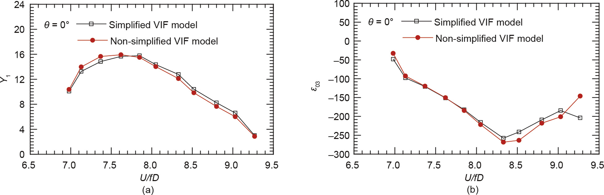
Fig. 9. Values for (a) Y1 and (b) ε03 for the centrally slotted box deck, identified with the simplified and non-simplified VIF models.
Fig. 10 shows the dimensionless stable amplitudes of the vertical VIV displacement for the sectional model system of the centrally slotted box deck, within the whole lock-in range, which were calculated according to the simplified VIF model shown in Eq. (5) and the non-simplified VIF model shown in Eq. (2). The corresponding measured values are also plotted in this figure. Again, the three sets of VIV stable amplitudes are clearly very consistent with each other, indicating that the simplified VIF model is also reliable for the centrally slotted box deck.
《Fig. 10》

Fig. 10. A comparison of the calculated and measured stable amplitudes of the vertical VIV displacement for the centrally slotted box deck.
4.2.3. Model parameters of a semi-closed box deck and verification
Fig.11 exhibits a comparison of the values of Y1 and ε03 for the semi-closed box deck under study, within the whole lock-in range, which were identified with the simplified VIF model shown in Eq. (5) and the non-simplified VIF model shown in Eq. (3), respectively [11]. Once more, the two sets of identified parameters agree well with each other.
《Fig. 11》
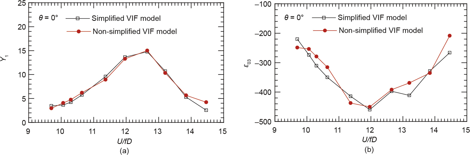
Fig. 11. Values of (a) Y1 and (b) ε03 for the semi-closed box deck, identified with the simplified and non-simplified VIF models.
Fig. 12 shows the dimensionless stable amplitudes of the vertical VIV displacement of the sectional model system of the semiclosed box deck, within the whole lock-in range, which were calculated according to the simplified VIF model shown in Eq. (5) and the non-simplified VIF model shown in Eq. (3), together with the corresponding measured ones. It is evident that the three sets of amplitudes are generally quite close to each other. This indicates that the simplified VIF model is reliable for the semi-closed box deck.
《Fig. 12》

Fig. 12. A comparison of the calculated and measured stable amplitudes of the vertical VIV displacement for the semi-closed box deck.
《5. Conclusions》
5. Conclusions
This paper presented a universal simplified mathematical model of nonlinear vertical VIF acting on bridge decks for predicting stable amplitudes of vertical VIV displacement of bridges with satisfactory accuracy. This simplified model was established based on the facts that the linear negative aerodynamic damping force is the primary power driving the VIV development and that the nonlinear positive aerodynamic damping force of the cubic term of velocity is the inherent factor of the self-limiting phenomenon of the vertical VIV. The universal simplified model of vertical VIF was verified by comparing the calculated and measured VIV responses of a sectional model system, and is thus applicable to the three typical box decks studied here; it also has a good prospect for application with other types of bridge decks.
《Compliance with ethics guidelines》
Compliance with ethics guidelines
Le-Dong Zhu, Xiao-Liang Meng, Lin-Qing Du, and Ming-Chang Ding declare that they have no conflict of interest or financial conflicts to disclose.
《Acknowledgements》
Acknowledgements
The work described in this paper was jointly supported by the National Natural Science Foundation of China (51478360, 51323013, and 50978204).


 京公网安备 11010502051620号


