


《1. Introduction》
1. Introduction
The invention of the first bridge was based on humans’ observation of natural phenomena, and on practice. The arch bridge is based on the arch, which is one of the most common shapes in nature. Arch bridges built with natural stones are elegant, strong, and durable, and were therefore widely used in ancient Rome and China; Zhaozhou Bridge is an outstanding example of an ancient arch bridge. In modern times, given the invention and application of high-quality artificial materials such as concrete, iron, and steel, the span of arch bridges has increased rapidly. Since 1875, when the first concrete arch bridge was built, it took more than 100 years for concrete arch bridges to reach a span of 400 m; the Wanzhou Yangtze River Bridge, which was built in 1997, was the first concrete bridge with a span over 400 m. In 2016, the Beipan River Bridge on the Shanghai–Kunming High-Speed Railway was completed with a span of 445 m, creating a new world record for the span length of concrete arch bridges.
The concrete-filled steel tube (CFST) arch bridge is an excellent type of steel-reinforced concrete composite bridge, in which the local stability of a steel tube is improved by the concrete filling it, while the toughness and strength of the concrete are improved by the external confinement of the steel tube. The CFST arch bridge was first developed in the Soviet Union in the 1930s, and was later abandoned after the construction of two such bridges, due to a failure to take advantage of its structure and construction. Chinese engineers have conducted thorough research into the mechanism and construction method of CFST arch bridges, and have promoted the construction of a large number of CFST arch bridges in China. During the past 20 years, more than 400 CFST arch bridges have been constructed in China, with a maximum span of 530 m. Moreover, the development of CFST arch bridges is still both rapid and promising (see examples in Fig. 1), and the span record for concrete arch bridges with a CFST skeleton continues to increase. To date, four steel-reinforced concrete arch bridges with a span of over 400 m have been created worldwide. All four of these bridges are in China, with three being completed in 2016—representing an amazing achievement in global bridge development (see examples in Fig. 2).
《Fig.1》

Fig. 1. CFST arch bridges in China. (a) Guangxi San’an Yong River Bridge (main span of 270 m, completed in 1998); (b) Wushan Yangtze River Bridge (clear span of 460 m, completed in 2005); (c) Anhui Huangshan Taiping Lake Bridge (main span of 352 m, completed in 2007); (d) Hurongxi Expressway Zhijing River Bridge (main span of 430 m, completed in 2009); (e) First Hejiang Yangtze River Bridge (main span of 530 m, completed in 2013).
《Fig.2》

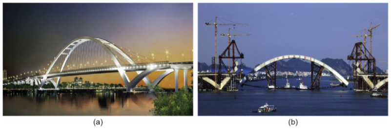
Fig. 2. Steel-reinforced concrete arch bridges in China. (a) Shanghai–Kunming High-Speed Railway Beipan River Bridge (main span of 445 m, completed in 2016);(b) Yunnan–Guangxi Railway Nanpan River Bridge (main span of 416 m, completed in 2016); (c) Chongqing–Guizhou High-Speed Railway Yelang River Bridge (main span of 370 m, completed in 2016); (d) Wanzhou Yangtze River Bridge (main span of 420 m, completed in 1997); (e) Guangxi Yongning Yong River Bridge (main span of 312 m, completed in 1996); (f) Zhaohua Jialing River Bridge (main span of 364 m, completed in 2012).
《2. Concrete-filled steel tube arch bridges 》
2. Concrete-filled steel tube arch bridges
2.1. Status of development
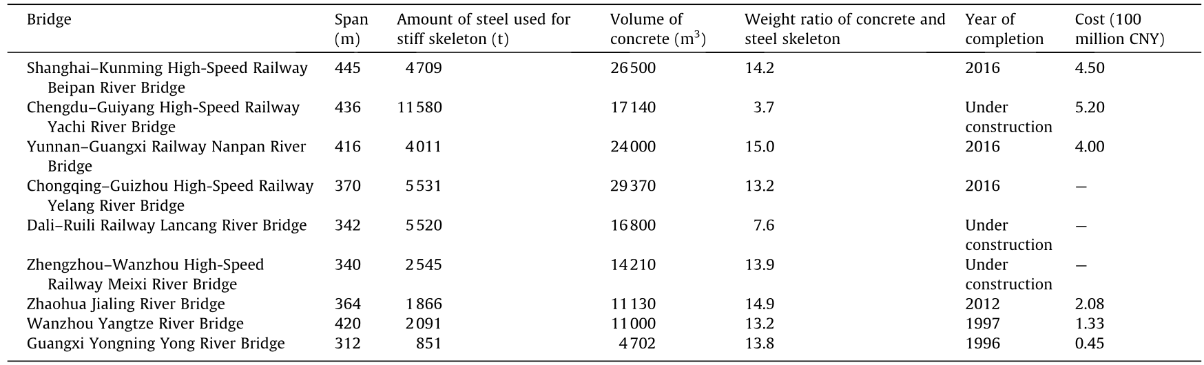
The first CFST arch bridge in China, the Sichuan Wangcang Dong River Bridge, was constructed in 1990. From then on, about 18 CFST arch bridges were built every year in China. Fig. 3 shows the increase in the total number of CFST arch bridges in China. According to the statistics, over 400 CFST arch bridges had been built in China by the year 2016; of these, 54 have a span of over 200 m, 11 have a span of over 300 m (Table 1), and four have a span of over 400 m. The First Hejiang Yangtze River Bridge, which opened in 2013, is the longest CFST arch bridge in the world, and ranks third in terms of the longest main span of all arch bridges. At present, three CFST arch bridges with a span of over 400 m are under construction, including the Zangmu Yarlung Tsangpo River Bridge on the Lhasa–Nyingchi Railway, which has a span of 430 m. Fig. 4 shows the increase in the maximum span of CFST arch bridges.
《Fig.3》
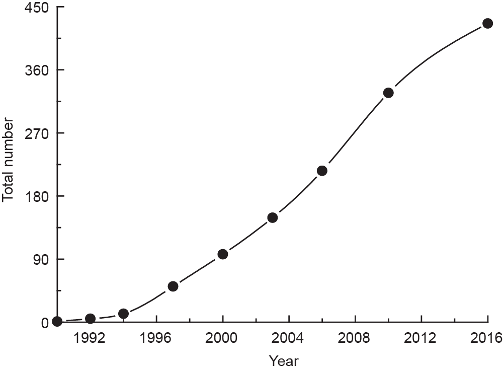
Fig. 3. Increase in the total number of CFST arch bridges in China over the years.
《Fig.4》

Fig 4 Increase in the maximum span of CFST arch bridges in China over the years.
《Table 1》
Table 1 List of completed CFST arch bridges in China with a span of over 300 m.

2.2. Erection of the steel tube arch truss
The erection of the steel tube arch truss is the most important stage in the construction of a CFST arch bridge. Three methods including cable-stayed fastening-hanging cantilever assembly, rotation construction, and large-segment lifting construction, have been widely used in China.
2.2.1. Cable-stayed fastening-hanging cantilever assembly
In 1968, Chinese engineers developed a closure technique utilizing the cable-stayed fastening-hanging cantilever assembly method with closure after loosening the steel wire rope. This method made it possible to construct arch bridges without supporting frames for the first time [1], and ensured the safety and convenience of the cantilever assembly of the arch ring within five segments and with a span of around 100 m. Due to the simplicity of the fastening-hanging system and the low construction cost, the unit construction cost of a CFST arch bridge with a span of 100 m is equivalent to that of a simply supported concrete bridge with a span of 30 m. This method has been applied to the erection of the arch rings of over 1000 arch bridges. A good representative of the application of this technology is Changsha Juzizhou Bridge, which is a double-curvature arch bridge over the Xiang River, and which was completed in 1972 with a total length of 1250 m and a maximum span of 76 m.
In 1994, a closure technique was developed that utilizes the cable-stayed fastening-hanging cantilever assembly method with closure before loosening the steel strand. This method was used to complete the cantilever assembly of a steel tube arch skeleton with a span of 312 m for the first time. The method uses a lifting jack to deploy and retract the cable-stayed steel strand, thereby achieving millimeter-level precision. The arch is fastened and consolidated segment by segment. Closure can be completed in a static state with only three segments, regardless of the number of segments assembled together, making this method suitable for the cantilever assembly of arch bridges with a span of over 100 m. This method has been used to complete the erection of hundreds of the arch rings of arch bridges, including Shanghai Lupu Bridge (main span of 550 m), the First Hejiang Yangtze River Bridge (main span of 530 m), the Wanzhou Yangtze River Bridge (main span of 420 m), and the Beipan River Bridge (main span of 445 m) on the Shanghai–Kunming High-Speed Railway.
The two abovementioned methods were simultaneously applied to the Hangzhou Fuxing Bridge (Fig. 5), thereby allowing the achievement of a high finishing speed (the closure of one span within two days). These methods also contributed to the accomplishment of erecting a 1376 m long, double-deck bridge with a total area of 70 000 m2 within two years.
《Fig.5》
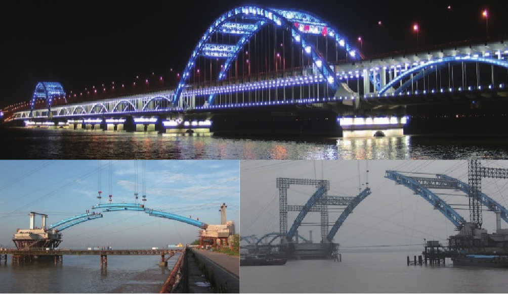
Fig. 5. Cable-stayed fastening-hanging cantilever assembly of Hangzhou Fuxing Bridge.
Chen and Yang [2] collected available information on the construction methods of 103 CFST arch bridges, and found that 67% of these bridges were constructed with the cable-shifting and cable-stayed fastening-hanging method. Among the 11 CFST arch bridges that have a span of over 300 m, 10 were constructed with this method.
2.2.2. Rotation construction
The rotation construction method for arch bridges was developed by Chinese engineers in 1977, and includes horizontal rotation, vertical rotation, and a combination method of horizontal and vertical rotations [3]. To date, the rotation construction method has been used in the construction of more than 70 arch bridges. A typical project using the horizontal rotation construction method is the Beipan River Bridge on the Guizhou Shuibai Railway, which is a deck-arch type of CFST arch bridge with a main span of 236 m. A typical project using the vertical rotation construction method is the Third Gui River Bridge in Wuzhou of the Guangxi Zhuang Autonomous Region, which has a main span of 175 m. A typical project using the combination method of horizontal and vertical rotations is Guangzhou Yajisha Bridge (Fig. 6), which is a half-through rigid-frame CFST arch bridge with a tie. This bridge has a span layout of (76 + 360 + 76) m, a rotation mass of 13850 t, and a horizontal rotation distance of 180 m, all of which still hold the world record. Rotation construction interferes the least with the space under the bridge, does not change the mechanical behavior of the structure in the process of rotation, and has a good safety performance. However, the construction of the rotary system, such as the rotary table, requires a great deal of investment, which hinders the application of the rotation construction method to arch bridges with longer spans.
《Fig.6》
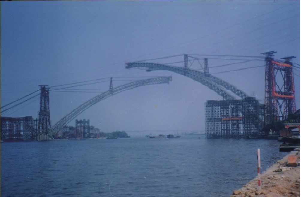
Fig. 6. Rotation construction of Guangzhou Yajisha Bridge.
2.2.3. Large-segment lifting construction
Two steel arch bridges have been constructed with the largesegment lifting construction method. One is Guangzhou Xinguang Bridge, which crosses the Pearl River [4]. This bridge was completed in 2007 and is a three-span continuous steel trussed arch bridge with a span layout of (177 + 428 + 177) m. The two side-spans of the bridge were assembled at the support in situ and then lifted together. The mid-span was divided into three parts, with a mass of 2850 t for the largest piece, and fabricated in the prefabrication field. These parts were then shipped to the bridge site and lifted to the support in order to complete bridge closure using the synchronous hydraulic-lifting technology. The whole process caused only 56 h of navigation delay.
The other bridge constructed using this method is the Third Fenghuang Bridge in Nansha District in Guangzhou, which was completed in 2017. This three-span steel trussed arch bridge with a tie has a total length of 510 m (Fig. 7) and a span layout of (40 + 61 + 308 + 61 + 40) m. The lifting segment has a length of 249.5 m and a total mass of 4690 t, and was shipped to the bridge site and then lifted in order to complete bridge closure using the synchronous hydraulic-lifting technology.
《Fig.7》

Fig. 7. Third Fenghuang Bridge. (a) Bridge after completion; (b) large-segment lifting of the main arch rib.
The large-segment lifting construction method minimizes high-altitude operations, and the stress of the arch truss can be reduced with temporary bracings during the construction, making it possible to increase the length of the lifted segment. In addition, the weight increase in the lifted segment can be solved using more lifting jacks. Therefore, the span of steel arch bridges can be increased further with the large-segment lifting construction method, making it a feasible construction method for super-long-span CFST arch bridges.
《2.3. Typical engineering examples》2.3. Typical engineering examples
The First Hejiang Yangtze River Bridge is the longest CFST arch bridge in the world at present (Fig. 1(e)), with a clear span of 500m. Based on the span calculation method for multi-span bridges, its bridge span length is actually 530 m, ranking third in terms of the longest span length of arch bridges around the world. This fourlane bridge is located on the Luzhou–Chongqing Expressway and was completed and opened to traffic in 2013. The bridge was designed by the Highway Planning, Survey, Design, and Research Institute of the Sichuan Provincial Transport Department, and was constructed by the Guangxi Road and Bridge Engineering Group Co., Ltd.
A half-through CFST arch truss was adopted for the main arch rib of the First Hejiang Yangtze River Bridge. The heights of the cross-section of the arch toe and of the arch crown are 16 m and 8 m, respectively, and the arch width is 4 m. Each rib consists of four tubes with a diameter of 1320 mm; the thickness of the tube varies at different sections with values of 22 mm, 26 mm, 30 mm, and 34 mm. C60 concrete was used to fill the tubes. The transverse steel tubes have a diameter of 762 mm and a thickness of 16 mm, and the web links have a diameter of 660 mm and a thickness of 12 mm. The arch truss was lifted and transported by the cable crane system; it was constructed by means of the closure technique in which cable-stayed fastening-hanging cantilever assembly is completed before loosening the steel strands.
2.3.1 Design, fabrication, and installation of the steel tube arch truss
In addition to the overall static and dynamic calculations that all bridges require, the design of a steel tube trussed arch bridge includes the conduction of a segment-lifting design. The steel tube arch truss of the First Hejiang Yangtze River Bridge consists of two ribs, each of which was divided into 18 lifting segments. Flange bolts and semicircle steel tube welding were used in the chords between different lifting segments, which not only increased the strength of the joint, but also made it convenient to construct. A horizontal wind bracing was set for each lifting segment to ensure the overall stability of the bridge after completion and to guarantee the stability of each segment during the cantilever assembly process. Temporary hinges for installation were set at the arch toes.
Large-segment lifting construction is favored by Chinese engineers during the fabrication and installation of steel tube arch trusses. The mass of the lifting segment usually ranges from 100 t to 200 t. At present, the span of the cable crane has reached 1196 m and the mass of the largest lifting segment has reached 400 t. Errors are inevitable during the manufacturing and assembly of lifting segments, and the load-carrying capacity of the steel tube arch truss is reduced as a result. Research shows that the in-plane antisymmetric error of the steel tube arch truss has a significant influence on its load-carrying capacity. In addition, the assembly of the steel tube arch truss will be affected by manufacturing errors.
The steel tube arch truss of the First Hejiang Yangtze River Bridge has a weight of 7270 t and was divided into 54 lifting segments by the Wuchang Shipbuilding Industry Co., Ltd. The arch has 18 horizontal wind bracings and 36 lifting segments, with the maximum segment having a weight of 192 t and a size of 4m*6m*45m. To improve the manufacturing precision of the lifting segments, a three-dimensional model of the bridge main arch was created. The arch camber was set by modifying the corresponding coordinates of the arch. The geometrical sizes of the bars were determined after considering the welding shrinkage, the precision of the cutting equipment, and assembly error. The cumulative error was eliminated by controlling the fabrication based on matching at each step. The overall plan of fabrication was as follows: fabrication of shell→ fabrication of element→section fabrication of string tube→coupling fabrication of unilateral 2 + 1 horizontal assembly →examination of the vertical assembly of the main arch rib →coating. It was verified that the coupling examination of the vertical assembly can be canceled when the manufacturing error of the lifting segment is controlled within 3 mm (Fig. 8). The last one-third of the lifting segments was completed directly by horizontal assembly (Fig. 9), which is checked through the cable-stayed fastening-hanging cantilever assembly and can thus ensure the line accuracy of the arch truss and the tight contact of the flange joint. Canceling the coupling check of the vertical assembly avoids the overturn risk of the gantry that is used to lift segments; it thus accelerates the manufacturing speed and reduces the cost, thereby providing experiences that are useful toward manufacturing steel tube arch trusses with longer spans.
《Fig.8》

Fig. 8. Coupling verification for the vertical assembly of the lifting segments of the arch truss.
《Fig.9》

Fig. 9. Coupling fabrication for the horizontal assembly of the lifting segments of the arch truss.
The two ribs of the steel tube arch truss of the First Hejiang Yangtze River Bridge were divided into 36 lifting segments. These segments were shipped to the bridge site, and then hoisted by the cable crane. During the process, the segments were stretched by nine groups of steel-strand cable-stayed buckles on each bank, three of which were temporary buckle cables and buckle hangers whose tension force was balanced by the back buckles in the buckle tower. Fig. 10 shows the overall arrangement of the fastening-hanging and hoist systems for the First Hejiang Yangtze River Bridge.
《Fig.10》

Fig. 10. Overall arrangement of the fastening-hanging and hoist system for the First Hejiang Yangtze River Bridge. (a) Overall arrangement of the buckle hangers and hoist system; (b) arrangement of buckle hangers.
The cable crane has a main span of 554 m and a lifting capability of 2000 kN. The main cable can be moved to the installation site for the components. The track cable consists of two groups of eight sealed coil ropes with a diameter of 50 mm. The height of the buckle tower, which is a concrete-filled steel tubular lattice, is about 150 m. The height of the hanging tower is 29.6 m; it is hinged at the top of the buckle tower.
The horizontal wind bracing and side-wind cables were assembled after completing the assembly of one lifting segment of each rib. Every half arch was divided into nine lifting segments, and the temporary hinge was fastened when six segments were assembled. The arch closure was conducted when all of the nine seg ments were assembled and the temperature was stable. It should be noted that the elevation and axis of the arch truss were adjusted using the buckle and side-wind cables before sealing the hinges and closure, respectively, to ensure the close contact of the flange joint (Fig. 11).
《Fig.11》
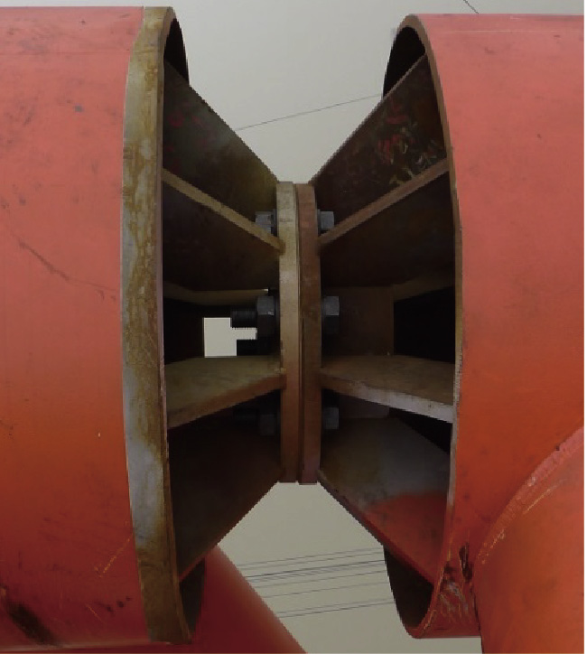
Fig. 11. Contact condition of the flange joint.
The installation of the 36 lifting segments and all sway bracings of the whole bridge took 58 days to complete, and the accuracy satisfied the specified requirements [5]. After closure, the cablestayed buckles were loosened symmetrically from the two banks and two ribs, from the toe to the crown of the arch, and the steel tube arch truss was formed. Table 2 summarizes the height differences of some symmetrical points in the arch ribs, which have a great influence on the load-carrying capacity; the maximum value among these is 0.03 m, which is far less than the critical value, L/3000 = 0.167 m. Table 3 shows the deviations of the arch axle line; the maximum value among these is 10 mm, which is far less than the critical value, L/6000 = 83 mm.
《Table 2》
Table 2 Retesting data for the height of the No. 1 to No. 9 segments of the arch ribs (unit: m).
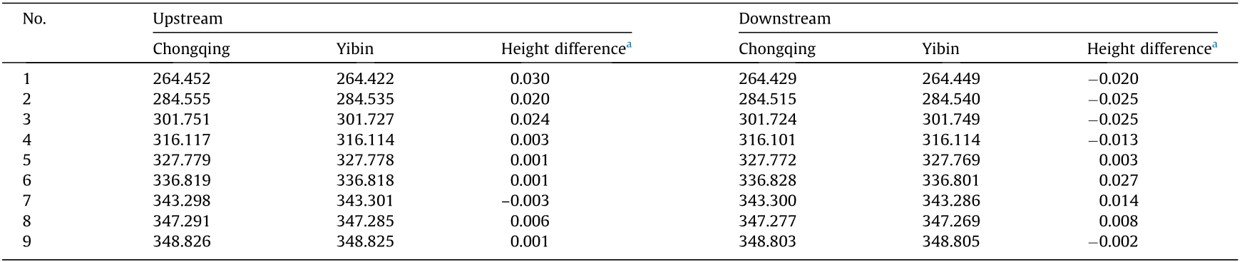
a Height difference of symmetric points in ribs.
《Table 3》
Table 3 Deviation data for the axles of the No. 3 to No. 9 segments of the arch axle line (unit: mm).

Positive values denote deviation in the upstream, while negative values denote deviation in the downstream. The symbol ‘‘—” indicates that the measuring tube of the segment was damaged or invisible.
2.3.2. In-tube concrete
(1) Working mechanics of steel tubes and concrete. The loadcarrying capacity and durability of CFST arch bridges depend on the interaction between the steel tube and the concrete filling the tube. Scholars in China have investigated and tested the shear bonding force, which can be divided into four categories: the chemical bonding force, mechanical bite force, macroscopic bite force, and frictional resistance [6]. Of these four forces, the chemical bonding force is relatively small and will vanish once local slip is initiated by small strains. The macroscopic bite force and frictional resistance will not come into play until a relatively large slip occurs due to large strain. The mechanical bite force forms after a slip occurs due to small strain, but before a large slip occurs due to large strain. De-bonding and separation between the tube and the concrete affect the shear bonding force and the local stability of the steel tube. To avoid this, two problems need to be solved: first, to guarantee the compactness of the concrete during casting; and second, to solve the problem of mismatching between the expansion and shrinkage of the concrete during its whole life cycle.
(2) Preparation technology of in-tube concrete. At present, two key issues need to be solved during the preparation of the filled concrete: These are a self-filling ability and a non-shrinkage characteristic, which are necessary in order to achieve synergy between the high fluidity and stability of the concrete during the construction stage, and to restrain the shrinkage of the concrete at each stage of the whole process. Chinese engineers have determined that the stability of concrete can be guaranteed by controlling the interfacial adsorption and dispersion and the shear behavior, while the viscosity of concrete can be ensured by controlling the viscosity of the interstitial fluid and the thickness of the water film [7]—thus realizing synergy between the high fluidity and stability of the concrete. The condensation of concrete can be solved via plastic expansion technology, while the self desiccation shrinkage of concrete can be solved by chemical shrinkage [8], shrinkage-compensation [9], and maintenance technology—thus ensuring the control of concrete shrinkage at each stage of the whole process. These methods can help to achieve the expansion and shrinkage design of the in-tube concrete, while permitting some compressive stress reserve according to the design requirement.
The development and application of these preparation technologies for high-fluidity, high-stability, and non-shrinkage concrete guarantee the convenience and efficiency of the construction of concrete-filled tubes; they also lay a foundation for solving the problem of de-bonding and separation between the tube and the concrete during the long-term service of the CFST.
(3) Development of the casting technique of in-tube concrete. The development of the pouring technique for the in-tube concrete of CFST arch bridges went through several stages: from the sub-compartment casting of concrete onsite, to the pumpingup pouring method, to the vacuum-assisted pumping-up pouring method.
To assure the compactness of the concrete that is cast in the tube, large-scale models cast with the normal pressure-casting method and with the vacuum-assisted pumping-up pouring method were tested and compared during the construction of the First Hejiang Yangtze River Bridge. The tests verified that in-tube concrete cast using the vacuum-assisted pouring method with a negative pressure of -0.07 MPa to -0.09 MPa is much more compact than concrete cast using the conventional pressure-pouring method. Based on the experimental results and on engineering practice, the vacuum-assisted pumping-up pouring method for in-tube concrete was developed [10,11]. The length of each tubular chord of the bridge arch truss is about 600 m. Each needed to be filled with nearly 800 m3 of C60 concrete using the three-level continuous vacuum-assisted pumping-up pouring method (Fig. 12). Continuous pumping-up pouring with multi-levels reduces the time that concrete stays in a high-fluidity condition and reduces pumping resistance; the number of levels is based on the volume of the in-tube concrete and on the construction capability. The instant upward deflection of the vault can be reduced by continuously adjusting the load using stay cables [12,13]. It took an average of 12 h to complete the pouring of the in-tube concrete of a chord, and 33 days to finish the pouring of the in-tube concrete for all eight chords of the main arch. At an age of three days, the compactness of the in-tube concrete near 144 flange joints was examined using the ultrasonic detection method; it was found that 100% of the points that were examined satisfied the requirements, and 92% achieved excellent quality, thereby demonstrating the pouring quality of the in-tube concrete. Moreover, the vacuumassisted pumping-up pouring method accelerated the concrete pouring speed, and thus reduced the construction cost.
《Fig.12》

Fig. 12. Layout of the three-level continuous vacuum-assisted pumping-up pouring method for in-tube concrete.
The invention of the vacuum-assisted pumping-up pouring method for in-tube concrete has successfully overcome the technical bottlenecks for the development of CFST arch bridges. With these advances in fabrication and installation techniques, the First Hejiang Yangtze River Bridge was completed in 2013 with a main span of 530 m, setting a world record for the longest CFST arch bridge. The total construction cost of the bridge was 260 million CNY, which was cheaper than the cost of any other type of bridge. For example, the cost of this bridge was 110 million CNY cheaper than the cost of the Second Hejiang Yangtze River Bridge, which is a concrete cable-stayed bridge with a main span of 420 m, and which was completed during the same period.
The load test of the First Hejiang Yangtze River Bridge (Fig. 13) showed that its construction quality achieved the design requirements in all aspects.
《Fig.13》

Fig. 13. The load test of the First Hejiang Yangtze River Bridge after completion.
《2.4. Study on the construction of longer-span CFST arch bridges》2.4. Study on the construction of longer-span CFST arch bridges
In 2013, with the construction of the world’s longest CFST arch bridge, a complete set of construction technologies for 500 m grade CFST arch bridges was developed. Based on this, Chinese engineers carried out a trial design and construction feasibility study of a 700 m grade CFST arch bridge, with a highway bridge in Sichuan as the basis [14] (Fig. 14). The preliminary conclusion was that both the static and dynamic performance of a CFST arch bridge with a net span of 650 m would meet the standard requirements, and that the construction could be completed with the existing equipment and technologies, using cable crane lifting and cablestayed fastening-hanging cantilever assembly. The 700 m grade CFST arch bridge could be used to replace the kilometric suspension bridge that is currently used for crossing valleys, and would have considerable economic benefits.
《Fig.14》

Fig. 14. Overall layout of the span of a 700 m grade CFST arch bridge.
《3. Concrete arch bridges with a CFST stiff skeleton》3. Concrete arch bridges with a CFST stiff skeleton
《3.1. Overview of development》3.1. Overview of development
The steel-reinforced concrete arch bridge, also known as the Melan arch bridge, was invented by the Austrian engineer Josef Melan in 1898. To construct this type of arch ring, the stiff steel skeleton is first set up; next, the molds for casting concrete are fastened onto it. Along with the casted concrete, the steel and concrete form the arch. In the 1990s, Chinese engineers first proposed using the CFST arch to replace the steel arch truss as the stiff skeleton in this type of bridge [15]; the use of a CFST arch in this way reduces the amount of steel used in the stiff skeleton by about half. Among the stiff skeleton concrete arch bridges that have spans larger than 300 m, only the Yachi River Bridge adopted structural steel as the stiff skeleton; all other eight bridges are stiffened with CFST.
The mass of the steel arch truss is only about 1/14 that of the concrete arch ring. Although in-tube concrete improves the loadcarrying capacity and rigidity of bridges, a CFST stiff arch skeleton must bear the self-weight of the concrete wrapping the arch ring, which is much greater than the sum of the secondary static load and the live load of the arch ring. Moreover, as the reserve of the initial compressive stress of the concrete in the steel tubular skeleton is small, it is very likely that the instantaneous tensile stress will exceed the allowable stress, making load adjustment necessary. Chinese engineers have developed a construction method that adjusts the load using stay cables [16] and that divides concrete in the arch ring by ring, and then casts concrete on multiworking platforms in the ring [17,18]. To be specific, in this method, the concrete in the arch ring is divided into a number of rings, and the concrete is cast ring by ring. After the concrete in one ring has gained sufficient strength and forms a composite structure with the stiff skeleton, the concrete in the next ring is cast. In this way, the load-carrying capacity of the arch ring is increased step by step and the load that is carried by the stiff arch skeleton is reduced. The depth of each ring is calculated to ensure that the structure remains secure after the load of cast concrete is added for each ring or each time [19]. Since it is impossible to finish casting the concrete in one ring at the same time, the instantaneous stress and deformation of the arch during the casting process may be much larger than those that occur after casting is finished. Therefore, casting on multi-working platforms is done to reduce the instantaneous stress and deformation of the stiff skeleton. Load adjustment by means of stay cables is adopted to maintain the instantaneous stress and deformation within the safe range, and to reduce the permanent stress of the stiff skeleton. It has been demonstrated that the construction method for concrete arch bridges that uses a CFST stiff skeleton, as proposed by Chinese engineers, has less risk, a shorter construction period, and a lower cost than the popular construction method that is used in many other countries, which involves suspended-basket grouting on both ends and a stiff skeleton in between.
In 2016, the longest concrete arch bridge in the world, the 445 m Shanghai–Kunming High-Speed Railway Beipan River Bridge, was built in China. Both this bridge and the Yunnan–Guangxi Railway Nanpan River Bridge, which has a span of 416 m, were originally designed to be built using the construction method of suspended-basket grouting on both ends and a stiff skeleton in between. However, that design was eventually abandoned, after thorough consideration, and was replaced by a construction method that adopted an all-span CFST stiff skeleton, adjusted the load using stay cables, divided the arch ring into five rings, and simultaneously cast concrete on six working platforms in each ring. This method was eventually shown to be successful [18]. Over the past 30 years, four steel-reinforced concrete arch bridges with a span greater than 400 m and nine such bridges with spans greater than 300 m have been built in China. In contrast, the greatest span of a steel-reinforced concrete arch bridge built in a foreign country is only 260 m over the past 100 years. This difference in span is mainly due to the different construction methods adopted.
Chinese engineers developed the cable-stayed fasteninghanging cantilever assembly technology in 1968 [1], the rotation construction method for arch bridges in 1977 [3], and the suspended-basket grouting technology for arch bridges in 2008 [20]. Although all three of these methods can be used to construct concrete arch bridges with spans under 400 m, the longest concrete arch bridge that has been constructed using these technologies is only 210 m. The existing concrete arch bridges with spans larger than 300 m are all steel-reinforced concrete arch bridges (Table 4). There are a total of four concrete arch bridges with spans longer than 300 m in other countries (Table 5), all of which were constructed with the cantilever assembly or suspended-basket grouting construction technology.
The steel tubular stiff skeleton of the Zhaohua Jialing River Bridge has a mass of 1866 t, which is 1/14.9 of the mass of the concrete in the arch ring. The total construction period of this bridge was two years shorter than that of the Mike O’Callaghan–Pat Tillman Memorial Bridge in the United States, which used the suspended-basket grouting construction technology, and the construction cost of the former was only 1/8 that of the latter (Table 6). Therefore, the suspended-basket grouting construction technology and cantilever assembly technology are not adopted when constructing concrete arch bridges with spans larger than 300 m in China.
《Table 4》
Table 4 Steel-reinforced concrete arch bridges with spans longer than 300 m in China.
The symbol ‘‘—” indicates unavailable data.
《Table 5》
Table 5 Concrete arch bridges with spans longer than 300 m in other countries.

《Table 6》
Table 6 Comparison of a steel-reinforced concrete arch bridge and a suspended-basket-grouting concrete arch bridge.

3.2. Adjusting the load using stay cables
The formula for adjusting the load by means of stay cables is as follows [16]:
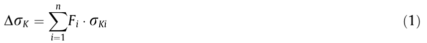
where Fi is the tension (force) applied to a pair of stay cables originally numbered as i; σKi is the stress at section K induced by a unitload applied to the ith pair of stayed cables, which can be obtained with sufficient accuracy using the finite element method or directfield measurement; and ∆σK is the stress at section K of the stayedcable.
In a process of continuous concrete casting, σKi remains unchanged while the section stress varies with time. When the stress at the critical section exceeds the allowable value, Fi should be adjusted to maintain the combined value of ∆σK and the stress of the critical section within the allowable range, and to keep the stresses of the other sections from exceeding the standard value. Based on having the σKi decrease with increased stiffness of the arch, the permanent stress at the critical section can be reduced by applying cable force when the stiffness is small, and by removing the force when the stiffness is large. The extent of the reduction in the permanent stress depends on whether the adverse effect on the stresses in the other sections is within the acceptable range.
The effectiveness of adjusting the load by means of stay cables relies on the acting positions of the cables, the magnitude of the cable force, and the timing of the application and removal of the cable force. By taking advantage of stay cables for the cantilever assembly of the stiff skeleton, the load can be adjusted at almost no cost. The concept of adjusting the load by means of stay cables originated in the construction of the Guangxi Yongning Yong River Bridge, and was further developed in the construction of the Yunnan–Guangxi Railway Nanpan River Bridge [16,18,19].
《3.3. Engineering practice》3.3. Engineering practice
3.3.1. The Guangxi Yongning Yong River Bridge
The Guangxi Yongning Yong River Bridge is a half-through concrete rib arch bridge that held the record for the longest span in the world in 1996. This arch bridge has a calculated span of 312 m, a rise-span ratio of 1/6, and a total width of 18.9 m [21].
This CFST stiff-skeleton-based concrete arch bridge has two ribs, each of which has the same width and varying height along the arch as the arch truss, and a total weight of 851 t. Each rib was divided into nine segments. It took 25 days to join the steel tubular arch trusses using the cable-stayed fastening-hanging cantilever assembly system, and 28 days to complete the pouring of the in-tube concrete. The 4702 m3 of concrete filling the two ribs was divided into four rings to be pumped into the CFST skeleton. It was the first time that loads were adjusted by means of three groups of stay cables with changing cable forces, and it took 40 h to fulfill the continuous pouring of the concrete from the ends at L/12 to the arch crown at L/2. During the whole pouring process, the transient stress remained within the codespecified range, almost no upward deflection occurred at the arch crown, and the maximum overall cable force was 2200 kN [16].
3.3.2. The Yunnan–Guangxi Railway Nanpan River Bridge
The Yunnan–Guangxi Railway Nanpan River Bridge is a CFST stiff-skeleton-based concrete arch bridge with a span of 416 m, which carries passenger and freight double-track railways, as shown in Fig. 2(b). The cross-section of the single-box arch ring has a height of 8 m and consists of triple cells. The widths of the arch foot and the arch crown are 28 m and 18 m, respectively. During construction, the steel tubular arch truss with a weight of 4000 t was first divided into 38 segments for the cable-stayed fastening-hanging cantilever assembly system, as shown in Fig. 15. Next, the concrete was pumped into the chord tube to form the CFST skeleton, and an additional 24000 m3 of encasing concrete, divided into five rings, was pumped to form the arch ring. The stiffness of the arch ring, which is 7.9 times higher than that of the CFST skeleton, met the requirement for carrying high-speed rail traffic. Fig. 16 shows the variation in the stress of the concrete in the upper and lower chord tubes of the CFST skeleton during the process of continuously casting the 6795 m3 concrete of the bottom slab, from the arch foot to the arch crown. It can be seen from Fig. 16 that the transient nominal tensile and compressive stresses were 24 MPa and 42 MPa, respectively, and that both occurred at the arch foot; these stresses far exceeded the stresses at the end of casting rings, while the stresses of the other sections were relatively small. The transient stress appeared to be large enough to cause the failure of the arch foot unless some countermeasures were taken. As can be seen from Fig. 14, the transient stress can be reduced by simultaneously casting concrete in multiple sections. In addition, installing stay cables that are inclined upward around the arch foot can effectively reduce the transient stress of the stiff skeleton at the arch foot, without having a significantly unfavorable influence on other sections [18].
《Fig.15》

Fig. 15. The (a) stiff skeleton and (b) concrete arch ring of the Yunnan–Guangxi Railway Nanpan River Bridge.
《Fig.16》

Fig. 16. Transient stress of the concrete in the (a) upper and (b) lower chord tubes of the CFST skeleton during the concrete casting of the bottom slab.
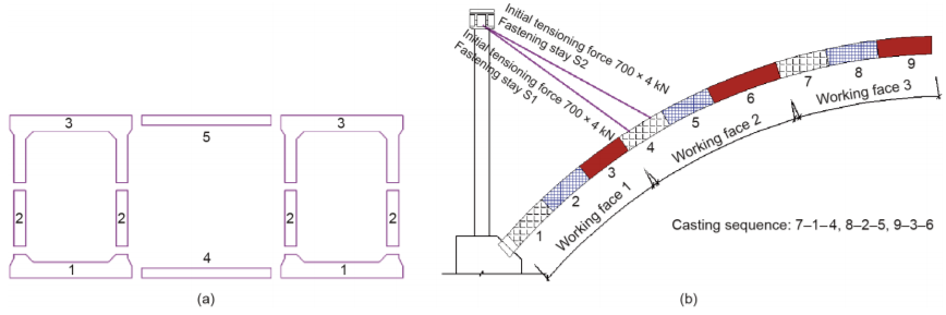
The arch ring of the Yunnan–Guangxi Railway Nanpan River Bridge, which is encased by a concrete volume of 24000 m3, is divided into five sub-rings that were cast by six working platforms. As illustrated in Fig. 17, each sub-ring was cast following the given sequence, which included three separate castings. Two groups of stay cables with a total force of 4000 kN were applied to the arch ring when the bottom slab was cast for the first time, and were later removed after the casting of the three sub-rings (i.e., the bottom slab, web, and top slab of the side box) was completed and the cast concrete had gained sufficient strength. The application of stay cables increased the compressive stress reserve of the concrete in the upper chord tube by 5.51 MPa, and decreased the permanent stress of the concrete in the lower chord tube by 5.4 MPa. Moreover, the allowable tensile stress was never exceeded during the casting.
《Fig.17》

Fig. 17. Illustration of the proposed concrete casting scheme for the Yunnan–Guangxi Railway Nanpan River Bridge. (a) Illustration of the five sub-rings of the arch ring; (b) illustration of the six working platforms (half).
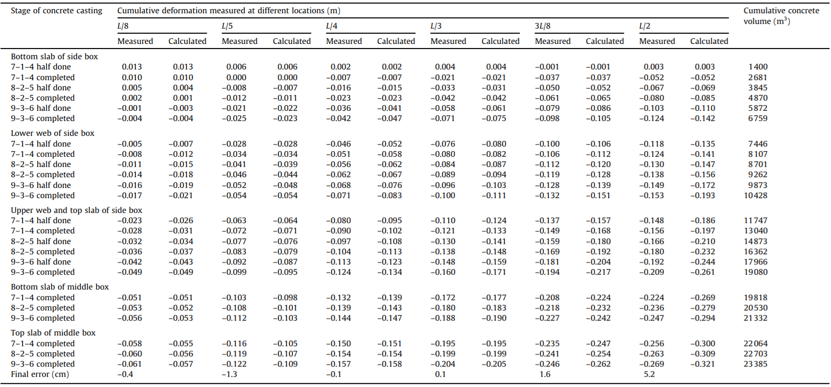
Without the stay cables, the maximum tensile stress of the concrete in the upper chord tube would have reached 7.39 MPa during the 35 casting stages, and the compressive stress of the concrete in the lower chord tube would have exceeded the allowable stress. In practice, due to the limited capability of producing and casting concrete at the construction site, each of the first three sub-rings (i.e., the bottom slab, web, and top slab of the side box) was completed in six castings, whereas each of the two remaining sub-rings (i.e., the top and bottom slab of the middle box) was completed in three castings. The 24000 m3 of encased concrete was cast a total of 24 times on the 4000 t CFST arch truss. Table 7 and Fig. 18 show the measured and calculated cumulative deformations of the arch truss during the casting of the five segments. It can be seen that the measured deformations of the arch truss were very close to the calculated values.
《Table 7》Table 7 Measured and calculated cumulative deformations of the arch truss and concrete volume during the concrete casting of the Yunnan–Guangxi Railway Nanpan River Bridge.
《Fig.18》

Fig. 18. Cumulative deformation of the arch truss during the concrete casting of the Yunnan–Guangxi Railway Nanpan River Bridge.
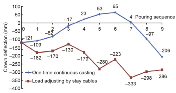
Fig. 19 compares the deflections at the arch top using the proposed casting scheme—which adjusts the load by stay cables and uses three-time castings and six working platforms—with onetime continuous casting from the arch foot to the arch top. It can easily be seen that the proposed casting scheme is much better than the one-time continuous casting scheme.
《Fig.19》

Fig. 19. Comparison of the deflection of the arch top between the two casting schemes.
The casting scheme for the encased concrete of the arch ring for the Nanpan River Bridge was proposed as follows: The arch ring was to be divided into five sub-rings for casting, and three groups of stay cables with varying force were to be applied to the arch ring, with the maximum cable forces of 3500 kN, 3000 kN, and 1500 kN, respectively. The proposed scheme would have been able to achieve continuous casting of the concrete from the arch foot to the arch top in every segment, and would have reduced the permanent stress at the control section of the stiff skeleton. The proposed scheme would also have facilitated a faster construction, leaving no joints in the concrete of the arch ring. Unfortunately, the proposed casting scheme could not be carried out in practice because the requirement of casting concrete at 500 m3 ·h-1 could not be met at the construction site.
《4. Final remarks》4. Final remarks
Although both the CFST arch bridge and the concrete arch bridge with a stiff skeleton can be categorized as steel-reinforced concrete arch bridges, the concrete of the CFST arch bridge is cast into the chord tube without using concrete shuttering. For this reason, the CFST arch bridge has the advantage of relatively easy construction, shortened time to construct the arch ring, lower construction cost, and faster increase in the span length. Seven CFST arch bridges with a span of over 400 m have been constructed or are currently under construction around the world. These longspan CFST bridges are widely used for highways, although a few are used for the railway. The Lhasa–Nyingchi Railway Zangmu Yarlung Tsangpo River Bridge, a 430 m long CFST arch bridge, is currently under construction and is expected to be completed in 2018. In future, the CFST arch bridge will also be widely used for high-speed railway if it is further verified that this type of bridge is insensitive to daily temperature variations. The concrete arch bridge with a stiff skeleton is very suitable for the high-speed railway due to its high stiffness, insensitivity to daily temperature variations, and good durability. This type of bridge has recently experienced rapid development in China. Five steel-reinforced concrete arch bridges with a span length larger than 300 m were simultaneously constructed on the high-speed railway network. The increasing span of the CFST arch bridge will promote the continuous increase in the span length of the concrete arch bridge with a CFST skeleton. Owing to their light structural components and relatively easy construction without large machinery, the CFST arch bridge and the steel-reinforced concrete arch bridge are suitable for mountainous areas and are more economical for crossing canyons than long-span suspension bridges or cable-stayed bridges.
Even though Chinese engineers have achieved success in the design and construction of CFST arch bridges and steel reinforced concrete arch bridges, the existing technologies still cannot meet the needs of the Silk Road Economic Belt and the 21st-Century Maritime Silk Road (Belt and Road Initiative), or those of the fast development of the highways and railways in China. Thus, technological advances should be continuously sought on critical issues such as improving the fatigue performance of welded joints, optimizing the control method for adjusting the force of stay cables during construction, optimizing the setup of concrete-casting segments and working platforms, further reducing the weight of the stiffened skeleton lowering the construction cost and risk, shortening the construction period, and continuously increasing the bridge span length. Finally, it is worth mentioning that the construction of a CFST arch bridge with a clear span of 650 m has been preliminarily proven to be feasible in an early study [14], and we look forward to the early emergence of a concrete arch bridge that spans over 700 m, which will become the new record-holder and will lead the development of arch bridges.
《Acknowledgements》
Acknowledgements
The authors would like to thank Deputy Chief Engineer Kejian Chen of the China Railway Eryuan Engineering Group Co., Ltd., the nationally recognized designer Tinglin Ma, the Management Department of the Yunnan–Guangxi Railway Nanpan River Bridge, affiliated with the China Railway 18th Bureau Group Co., Ltd., Chief Engineer Yu Han of Guangxi Road and Bridge Engineering Group Co., Ltd., and Deputy Chief Engineer Tingmin Mu of Sichuan Communication Surveying and Design Institute for providing materials for this paper, and thank the National Natural Science Foundation of China (51738004) for the support.
《Compliance with ethics guidelines》
Compliance with ethics guidelines
Jielian Zheng and Jianjun Wang declare that they have no conflict of interest or financial conflicts to disclose.


 京公网安备 11010502051620号


