
《1. Introduction》
1. Introduction
Due to the rapid development of urbanization and the rising demand for infrastructure construction, there is a serious shortage of urban land resources, and the conflict between the supply and demand of space capacity is increasingly prominent. Therefore, China has moved forward the concept of underground and intensive development for traffic and municipal public utilities. The 13th Five-Year Plan (2016–2020) clearly proposes to establish and improve the development demand for urban underground space. National planning guidelines on underground space exploitation, as represented by underground utility tunnels, underground parking lots, and ‘‘sponge cities,” have been issued in succession; of these, the aim for utility tunnel construction alone is as much as 2000 km each year. Tunnel-boring machines (TBMs) are the main equipment for the construction of trenchless underground engineering projects such as rail transit, municipal engineering, railway tunnels, and diversion tunnels, and will play an increasingly important role in the foreseeable future.
Due to their high construction efficiency, low environmental disturbance, and safe reliability, the conventional circular TBMs, which are the main equipment of the trenchless method, have played an important role in urban railway traffic engineering. However, this technology still contains some inherent defects such as a low utilization ratio of tunnel sections and a single crosssection type. The development of a tunnel that can satisfy the low overburden, high utilization ratio of tunnel sections, along with ideal cross-sections that are suitable for various purposes, has been an important development trend in future underground space exploitation. Meanwhile, the successful applications of the double-O-tube (DOT) shield machine, rectangular pipe-jacking machine, and horseshoe-shaped TBM show that these devices have won market recognition with their strong adaptability, economy, and security. Therefore, it is anticipated that these machines will become the main trend in future TBM development.
《2. Overview of the non-circular TBM》
2. Overview of the non-circular TBM
《2.1. Double-O-tube, multi-circular face, and quasi-rectangular shield machines》
2.1. Double-O-tube, multi-circular face, and quasi-rectangular shield machines
The technologies of the DOT [1] and multi-circular face (MF) shield machines [2] (Fig. 1(a) and (b)) were mainly developed in Japan. Compared with a parallel twin tunnel, the width of a cross-section excavated by a DOT shield machine is much narrower; compared with a single tunnel holding two parallel tracks, the height is also lower. These space-saving differences (Fig. 1(c)) cause DOT shield machines to be mainly applied to the integrated excavation of subway stations and utility tunnels. However, owing to the complex excavation cross-sections and relatively large ground disturbance of DOT and MF shield machines, the ‘‘piggyback soil” phenomenon can easily occur: Soil can adhere to the TBM shield body and accumulate during TBM advancement, forming so-called ‘‘piggyback soil.” This adverse phenomenon makes it difficult to control ground settlement.
《Fig. 1》
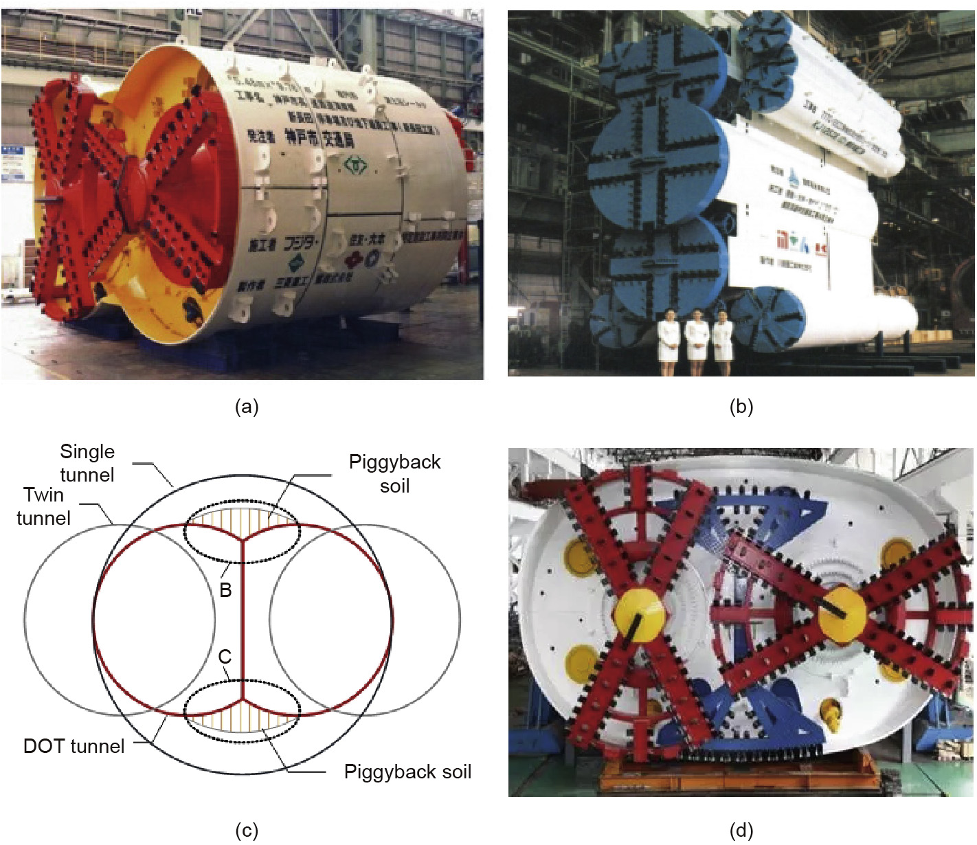
Fig. 1. (a) DOT shield machine; (b) MF shield machine; (c) cross-sections of parallel twin tunnel and DOT tunnel; (d) quasi-rectangular shield machine↑.
↑http://www.tunnelling.cn/PNews/WeChatDetail.aspx?weChatId=102.
A quasi-rectangular TBM was developed based on the DOT shield machine by increasing the eccentric multi-shaft cutterhead in order to excavate the blind areas at the B and C zones (Fig. 1 (c)). The excavation cross-section, whose upper and bottom shapes are circular arcs, has an ellipse-like quasi-rectangular shape that has improved the bearing capacity of the equipment and segments, solved the piggyback soil problem, and reduced ground disturbance (Fig. 1(d)).
《2.2. The rectangular TBM》
2.2. The rectangular TBM
Unlike a conventional circular cross-section, a rectangular cross-section can reduce the volume of an earthwork excavation and the disturbance of the surrounding environment, and can improve the utilization ratio of the tunnel section. Therefore, the rectangular TBM is especially suitable for underground engineering projects with a rectangular cross-section, such as utility tunnels, pedestrian crossings, and subway entrance passageways. In order to realize the full face excavation of a rectangular crosssection, the excavation system can be divided into parallel shaft types [3,4] (Fig. 2(a) and (b)), DPLEX types [5,6] (Fig. 2(c) and (d)), and modular types [7,8] (Fig. 2(e) and (f)).
《Fig. 2》

Fig. 2. (a) Overlap cutterheads; (b) a copy cutterhead; (c) wagging cutterheads; (d) an R-swing shield machine; (e) paddle-type cutterheads; (f) combined cutterheads.
《2.3. The horseshoe-shaped TBM》
2.3. The horseshoe-shaped TBM
Compared with a conventional circular cross-section, a horseshoe-shaped cross-section (Fig. 3) has a higher utilization ratio of the cross-section and better mechanical behavior; therefore, it has become a common cross-section for railway and highway tunnels.
《Fig. 3》

Fig. 3. The world’s first horseshoe-shaped TBM.
A horseshoe-shaped TBM can complete the excavation, muck transportation, and segment lining at the same time in a safe, environmentally friendly, and efficient manner. In the construction process of railway or highway tunnels, prefabricated inverts need to be laid in the bottom of the bored tunnel. Because the invert volume of a horseshoe-shaped tunnel is much smaller than that of a circular tunnel, around 30% of the concrete can be saved if a tunnel is excavated by a horseshoe-shaped TBM.
《3. Key technologies and application of the rectangular pipejacking machine》
3. Key technologies and application of the rectangular pipejacking machine
《3.1. Project profile》
3.1. Project profile
Fig. 4 shows the location of Hongzhuan Road, which undercrosses the Zhongzhou Avenue project. This project is composed of four tunnels, which include two bidirectional four-lane tunnels and two non-motorized vehicle lane tunnels. The cross-section dimensions of the 105 m long tunnel are 10.12 m width by 7.27 m height. The tunnel mainly goes through silt and silt fine sand with an overburden of 3.2–4 m. The super-large rectangular pipe-jacking machine being used for this project has the following parameters: a drive power of 1080 kW, a maximum thrust of 11 000 t, and a rated maximum advancing speed of 40 mm•min-1.
《Fig. 4》

Fig. 4. The layout of tunnels in the Hongzhuan Road undercrossing of the Zhongzhou Avenue project.
《3.2. Key technologies of the rectangular pipe-jacking machine》
3.2. Key technologies of the rectangular pipe-jacking machine
3.2.1. Thin rectangular shield
Unlike a conventional circular TBM, a rectangular pipe-jacking machine makes it difficult to form a stable natural arch in the upper part of the tunnel, due to the larger horizontal span produced by this machine, which will deform due to heavy loads. Deformation of the shield will decrease the quality of the slurry sleeve, and the overweight shield will increase the cost of manufacture, transportation, and usage. Therefore, the weight of the shield must be reduced as much as possible to satisfy the requirements of strength and stiffness [9].
(1) Load calculation model. The shield mainly bears the soil and water pressure and the ground dynamic load pressure. Due to the low overburden, the influence of the ground dynamic load cannot be ignored, and a quantitative analysis of the load on the upper tunnel should be performed. The load distribution on a rectangular pipe-jacking machine is shown in Fig. 5.
《Fig. 5》

Fig. 5. Load calculation model of a rectangular pipe-jacking machine. B: outer width of tunnel; a1 : width of unloading arch; D0 : height of tunnel; φ = tan-1 f kp , where f kp is the solid coefficient of soil; h1 : height of unloading arch; H: depth of overburden.
When the overburden is less than the outer diameter of the pipeline, the standard value of the vertical earth pressure on top of the machine is calculated by Eq. (1) [10]:

where Fs1 (kN•m-2) is the standard value of the vertical earth pressure on top of the machine, γsi (kN•m-3) is the unit weight of the overburden layer, hi (m) is the respective soil thickness above the TBM, and Fq is the ground dynamic load (kN• m-2).
When the pipe is above the groundwater level without regard for the effect of head pressure, the standard value of the lateral earth pressure is calculated by Eq. (2) [10]:

where Fc (kN•m-2) is the standard value of the lateral earth pressure, D1 is the height of the shield, and Ka is the coefficient of the active earth pressure.
(2) Optimization design of the shield structure. The front shield is designed as a quasi-rectangle with an upper arch, which consists of a tapered front cross-section and a box-type rear crosssection in order to improve the mechanical behavior (Fig. 6(a)). The load acting on the front shield in accordance with the results of Eqs. (1) and (2) should be analyzed by the finite element method [11]. According to the finite element analysis of the front shield, it is found that the maximum stress of the front shield should be less than 85.329 MPa (Fig. 6(b)) in order to satisfy the operating requirements. The maximum deformation of the front shield is 4.6134 mm, and is located at the middle of the rear part of the front shield (Fig. 6(c)).
In order to improve the mechanical behavior and deformation of the shield, it is recommended to increase the vertical support beam between the gusset plates to enhance structural stiffness (Fig. 6(d)). The stress distribution and deformation of the front shield after optimization are shown in Fig. 6(e) and (f), respectively, under the same load condition.
《Fig. 6》

Fig. 6. (a) Structure design of the front shield; (b) stress distribution of the front shield; (c) deformation of the front shield; (d) optimized structure of the front shield; (e) stress distribution of the optimized front shield; (f) deformation of the optimized front shield.
After optimization, the maximum deformation and stress values of the front shield are reduced by 26.0% and 31.6%, respectively. Although the weak stress spots still exist, there is a substantial improvement in stiffness (Table 1).
《Table 1》
Table 1 Calculation results comparison of the front shield before and after optimization.

3.2.2. The multi-cutterhead excavation system
Because the minimum overburden is 3 m, ground disturbance will influence the original driving conditions and may even cause traffic accidents. Since a rectangular tunnel has a relatively large excavation area, it will have many blind areas if a single circular cutterhead is used. Therefore, the rectangular pipe-jacking machine adopts the design of a multi-cutterhead excavation system.
(1) Multi-cutterhead excavation system. In response to the demand for higher coverage of the excavation area, the machine is equipped with six spoke-type cutterheads, which consist of three front and three back cutterheads arranged with parallel shafts; thus, the excavation area of adjacent cutterheads is mutually overlapped. The excavation diameter of the cutterhead is equal to the outer diameter of the segment, so the excavation rate is more than 90%. In addition, the number of agitators in the back part is greater than that in the front part in order to extend the agitation area to ensure smooth muck transportation. The machine is also equipped with scrapers to guarantee the excavation diameter.
(2) Muck flow field analysis. Using the Herschel-Bulkley rheological model in the ANSYS Fluent software, a flow field simulation of the soil was carried out. Based on a determination of the properties of the silty clay in Zhengzhou, the muck flow field was found to conform to the Herschel-Bulkley nonlinear constitutive equation model. A Fluent simulation analysis of the excavation area flow field was made, based on the following data: an improved soil density of 1480 kg•m-3, a yield viscosity μ0 of 680 Pa•s, a static shear stress  of 13000 Pa, a consistency index k of 1, a power law index n of 1.1, and a cutterhead speed of 1 r•min-1. The relationship between the yield viscosity g and shear rate t is as follows [12]:

Fig. 7 shows that the soil is agitated evenly in the rotation area of the cutterheads, especially in the overlapped area; as a result, the ground disturbance is relatively small. However, some blind zones still exist.
《Fig. 7》

Fig. 7. Velocity distribution of the muck flow field in the Z direction. (a) The front cutterheads (Z = 600); (b) the muck flow field of the rear cutterheads; (c) the combined cutterheads.
As shown in Fig. 8, the cutterheads form their respective flow fields in different cross-sections. The muck can flow among the cross-sections, which is favorable for the mixing of soilconditioning additives and soil, in order to improve the plastic flow state while benefiting the muck transportation of the screw conveyor.
《Fig. 8》

Fig. 8. Velocity vector of the muck flow field in the X direction.
《3.3. Application analysis》
3.3. Application analysis
A super-large rectangular pipe-jacking machine is shown in Fig. 9(a). At present, two tunnels consisting of a driveway lane and a non-motorized vehicle lane have been successfully broken through, and the machine performed well during the tunneling.
(1) During the construction process, the shield of the rectangular pipe-jacking machine remained in good condition, with a maximum deformation of the top center of the shield of 3.2 mm; no fatigue cracks were produced, as shown in Fig. 9(b).
《Fig. 9》
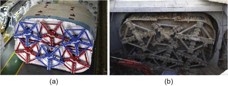
Fig. 9. (a) Super-large rectangular pipe-jacking machine; (b) front shield after breakthrough.
(2) As shown in Fig. 10, the maximum differential pressure between the two sides of the excavation chamber was less than 0.5 bar (1 bar = 105 Pa) and the maximum settlement was no more than 18 mm in the advancing process. This demonstrates that the multi-cutterhead design has the advantages of uniform pressure distribution in the excavation chamber, good muck fluidity, and small surface disturbance.
《Fig. 10》

Fig. 10. The changing curve of the soil pressure and settlement in the advancing process.
《4. Key technologies and application of the horseshoe-shaped TBM》
4. Key technologies and application of the horseshoe-shaped TBM
《4.1. Project overview》
4.1. Project overview
The Menghua Railway connects the west area of the Inner Mongolia Autonomous Region with central China. Baicheng Tunnel, which makes up part of this railway, is located in Jingbian County, Shaanxi Province; it is a 3345 m long double-track electrified railway tunnel with a maximum overburden of 81 m. The crosssection of the tunnel is of a horseshoe shape, of which the upper part is a circular arch and the bottom is slightly flat with a smaller radian of the two sides. The tunnel will be mainly built in silty sand, fine sand, and sandy loess, as shown in Fig. 11. The entire alignment of the tunnel runs in a straight line, with a maximum track gradient of 5‰. The longitudinal slope of the tunnel is a herringbone slope, with successive slope gradients/lengths of 4.5‰/1935 m, 3‰/900 m, and 11‰/510 m.
《Fig. 11》

Fig. 11. The geological conditions of Baicheng Tunnel.
The horseshoe-shaped TBM that is being used for Baicheng Tunnel has a width of 11.9 m, a height of 10.95 m, an excavation area of 106 m2, a total driver power of 1980 kW, a maximum thrust of 14080 t, and a maximum advance speed of 60 mm•min-1.
《4.2. Key technologies of the horseshoe-shaped TBM》
4.2. Key technologies of the horseshoe-shaped TBM
4.2.1. Segment erection system
Regarding the horseshoe-shaped cross-section, the segments have different surface curvatures, various shapes, a biased center of gravity, and a large weight, all of which cause a complex erecting path and high erecting precision. Fig. 12 shows a schematic diagram of the segment erection.
《Fig. 12》
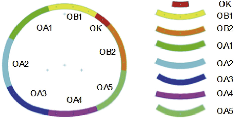
Fig. 12. Schematic diagram of the segment erection.
(1) Multi-degrees-of-freedom segment erection system. This was designed in order to reduce the deviation of the segment erection and improve the grasping stability from multiple points, as shown in Fig. 13(a). The main structure includes a rotating ring, longitudinal telescopic mechanism, and pick-up unit. The rotating ring moves around the Z axis, and the longitudinal telescopic mechanism realizes an extension and retraction function by the driving of cylinders.
《Fig. 13》

Fig. 13. (a) Segment erection system: 1. rotating ring, 2. longitudinal telescopic mechanism, 3. pick-up unit. (b) Pick-up unit: 1. extension cylinder, 2. guide post, 3. swinging cylinder, 4. lift cylinder, 5. lock cylinder, 6. lock device, 7. deflecting cylinder.
The mechanical pick-up unit (Fig. 13(b)) mounted on the longitudinal telescopic mechanism can grasp and retain segments for the entire duration of the positioning operations; it has the three independent movements of swinging, pitching, and rolling. The extension cylinder controls the movement along the Z0 axis, and the swinging cylinder can completely revolve around the Z0 axis. In addition, the rotations around the X0 and Y0 axes are separately driven by a lift cylinder and a deflecting cylinder, respectively. Therefore, the multi-degrees-of-freedom segment erection system ultimately completes the complex trajectories of the segment erection. Fig. 14 shows the segment erector.
《Fig. 14》

Fig. 14. The segment erector.
(2) Electro-hydraulic integrated-control technology of the erection system. The electro-hydraulic integrated-control technology used by the erector can reduce the system impulsion, continuously variable transmission, and differential pressure compensation in order to overcome the speed influence produced by the changeable load. The ramp time is implanted in the electro-hydraulic integrated-control system so as to eliminate the rigid impact and enhance the stability of the system. Fig. 15 shows the segment erection process. Fig. 15(a) to (h) respectively stands for erector attitudes when erecting segments OA4, OA3, OA5, OA2, OB2, OA1, OB1, and OK in sequence. Segments are erected in exactly this way.
《Fig. 15》
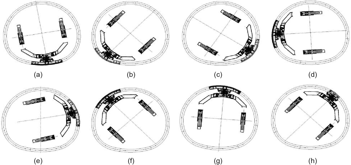
Fig. 15. Segment erection process.
4.2.2. Soil-conditioning test
(1) Test scheme. The large excavation area of the horseshoeshaped TBM may have an uneven agitating effect on the muck among the cutterheads; therefore, if the soil conditioning has not had a good result, it will lead to excessive cutterhead torque, unsmooth muck transportation, or even failure of the screw conveyor. A series of slump tests, agitating tests, and permeability tests were performed using common soil-conditioning agents such as foam, bentonite slurry, and foam and water in order to develop an appropriate soil-conditioning program with good plasticity and fluidity for this project. The experimental results are analyzed and the test method is shown in Fig. 16 [13].
《Fig. 16》

Fig. 16. Test scheme of soil conditioning.
(2) Test analysis. With an increase in water content, the slump of the soil samples increased. After water addition, the fluidity of the muck was better, but the plasticity was slightly worse, as shown in Fig. 17(a). The slump of the soil sample increased with the increase in the injection ratio of the foam or the bentonite slurry, as shown in Fig. 17(b). In addition, when the foam injection reached a certain amount, the slump did not change, despite an increase in foam injection. Foam that makes the soil loose can greatly reduce the density and simultaneously increase the plasticity of soil. The cohesion of the clay was significantly enhanced with an increase in the injection ratio of the bentonite slurry; however, compared with foam, the improvements in plasticity and fluidity were less significant.
《Fig. 17》

Fig. 17. (a) Soil sample slump by water injection; (b) soil sample slump by foam or bentonite slurry injection.
According to the above analysis, foam can improve the slump of soil and increase the flowability, cohesiveness, and water retention of soil to meet the requirement of a fluid plastic soil. In comparison, although bentonite slurry can effectively improve the cohesiveness of soil, it has a higher cost. Therefore, the project was designed to adopt foam injection with an injection ratio of 27%.
《4.3. Application analysis》
4.3. Application analysis
As of June 2017, Baicheng Tunnel has successfully advanced by 1704 m, with an average daily advance of 12 m.
(1) The segment erection system performed well during the construction process. As shown in Fig. 18, the average erection time for a ring is 55 min, which realizes safe and efficient segment erection.
《Fig. 18》
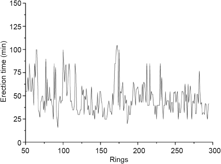
Fig. 18. Erection time for each ring.
(2) In the construction process, the soil conditioning causes the muck to have better flowability and plasticity, as shown in Fig. 19 (a). An optimized soil-conditioning program decreased the average cutterhead torque by 6%, greatly reduced the fluctuation of the cutterhead torque, and enhanced the stability of the cutterhead (Fig. 19(b)).
《Fig. 19》

Fig. 19. (a) Soil-conditioning effect at the jobsite; (b) comparison of cutterhead torques before and after soil conditioning.
《5. Conclusions and outlook》
5. Conclusions and outlook
《5.1. Conclusions》
5.1. Conclusions
This paper presents several key technologies, including a shield structure optimization design, a multi-cutterhead excavation system, a special-shaped segment erection, and a soil-conditioning test, in order to solve frequently encountered problems including shield deformation and ground disturbance in the design process. It also discusses the manufacture and tunneling of the rectangular pipe-jacking machine and horseshoe-shaped TBM, and puts forward a set of solutions for the practical application and popularization of the non-circular TBM. The main conclusions are as follows:
(1) The front shield adopts an upper arch and box-type structure, which can significantly enhance the stiffness of the shield. In addition, the vertical support beam at the rear part of the front shield effectively reduces the deformation of the shield.
(2) A multi-cutterhead excavation system adopts three front and three back cutterheads arranged with parallel shafts in order to guarantee the excavation area. The muck can flow among the cross-sections, which is favorable for soil conditioning and muck transportation.
(3) A multi-degrees-of-freedom segment erector can preferably complete segment erection with different surface curvatures; electro–hydraulic integrated-control technology can greatly improve the safety and stability of grasping from multiple points.
(4) A soil-conditioning test should be conducted before tunneling with a large non-circular TBM in order to determine the appropriate medium and injection ratio.
《5.2. Outlook》
5.2. Outlook
Due to rapidly advancing urbanization and a shortage of land resources, there is an urgent demand for underground space development. For a long time, municipal utility pipelines have been under unreasonable redundant construction that brings potential hazards. Therefore, utility tunnels constructed by the subsurface excavation method have become the priority direction in underground space development due to their ability to carry cable, water, and gas pipelines; their ability to support maintenance and monitoring functions; and their safety, economy, and low environmental disturbance (Fig. 20). In view of the current development of utility tunnels, the rectangular and horseshoe-shaped cross-section design and shield methods have broad application prospects.
《Fig. 20》

Fig. 20. (a) Rectangular utility tunnel‡; (b) horseshoe-shaped utility tunnel.
‡http://www.sohu.com/a/123557058_481408.
The diversity of underground space exploitation will cause the demand for non-circular TBMs to continue to increase in future. Therefore, in order to better adapt to underground space development, a non-circular TBM needs to possess a strong adaptability for special-shaped sections and a high degree of automation and intelligence. It must have the capability to combine with big data application and intelligent manufacturing in order to become precision intelligent high-end equipment. The main development directions are as follows:
(1) Adaptive technique for non-circular cross-sections. This technique involves the accomplishment of a full face excavation for non-circular cross-sections, the optimization of muck agitation, and a resolving strategy for blind areas. It can keep the excavation chamber pressure balanced and reduce ground disturbance through soil conditioning in real time; in addition, it can enhance the efficiency and accuracy of segment erection based on intelligent advancing technology and an accurate attitude control system.
(2) Remote monitoring and maintenance and big data techniques. The use of the Internet of Things and big data can enhance the informatization level of the non-circular TBM. To be specific, the use of these technologies can realize the functions of early warning, fault prediction, and diagnosis through the real-time monitoring of equipment. New knowledge and rules will be obtained from collecting and storing life-cycle information data from the non-circular TBM in the process of design, manufacture, tunneling, and operational maintenance, using big data analysis to promote the all-round upgrading of the non-circular TBM.
(3) Intelligent control technique. An intelligent industrial sensor should be added to improve the perception ability of the machine toward itself and ground conditions, and to conduct research on the control strategy. The establishment of an expert intelligent control system will contribute to realizing the intelligent control objectives of perception, learning, judgment, and making, which will allow the non-circular TBM to avoid excessive reliance on manual operation experience and to achieve safe and efficient advancement.


 京公网安备 11010502051620号


