
《1. Indroduction》
1. Indroduction
Surface integrity has great significance for the quality and performance of machined components, and has therefore been increasingly recognized by industry. In particular, within certain industries that require high reliability, such as the aerospace industry, surface integrity is one of the most relevant indexes used to evaluate the quality of machined parts. Thus, obtaining updated knowledge on surface integrity is of great interest to both the academic community and industry [1]. Surface integrity not only comprises surface topographical features [2,3], but also includes all of their physical, mechanical, metallurgical, chemical, and biological properties and characteristics [4]. Since most manufacturing operations directly affect these properties, the objective of studying surface integrity is to ensure the required service properties of surfaces in part and product manufacturing. Focused research activities in surface integrity are widespread due to increasing demands for surface integrity application in industry, which are caused by industry’s need for a better understanding of the functional performance of components and that performance’s dependence on the surface integrity generated from various manufacturing processes.
The CIRP Conference on Surface Integrity (CSI) discusses recent technical and scientific advancements, and future trends. This event aims to provide an international forum for researchers to present and exchange the latest achievements in surface-integrity-related research that have great significance in manufacturing and product quality, and that give insight into scientific knowledge on the formation and evolution of surface integrity in various surface processes. The conference includes keynote speeches, an expert panel discussion, oral presentations, posters, and more. More than 200 researchers participated in the CIRP Conference on CSI (2018) from various countries and regions, including China, France, Germany, Ireland, Japan, Poland, Singapore, Sweden, the United Kingdom, and the United States.
This paper comments on the CSI 2018 keynote speeches, which reported on recent progress and achievements in theoretical and experimental investigations on surface integrity in manufacturing processes. The topics covered here include subsurface damage from machining hard and brittle materials, three-dimensional (3D)-printed hydrogel structures, residual stress in metal additive manufacturing (AM), process signatures, predictive modeling, and multiscale modeling.
《2. Machining hard and brittle materials》2. Machining hard and brittle materials
In recent years, hard and brittle materials have been used in an increasing number of applications in various fields such as communication, optics, and aerospace. Due to their poor machinability, surface and subsurface damage tend to be left on workpieces that are composed of hard and brittle material, making it necessary to analyze their surface integrity. Ductile regime machining assesses brittle materials in terms of their mechanics and materials. If the machined surfaces of a brittle material are free of cracks and chips, the machining process is considered to be within the ductile regime; if not, the process is considered to be within the brittle regime [5]. Several influential factors, including material properties, machining conditions, and tool parameters, have a major influence on the dislocation and slip of materials during the machining process [6].
Material-removal mechanisms vary in terms of their strain rates [7], and cutting speed has a significant effect on the surface quality of variable compliance parts [8]. When the strain rate increases, the material-removal mechanism shifts from the ductile regime into the brittle regime. Strain rate has a strong influence on a material’s brittleness and micro-hardness; a higher strain rate always results in a more brittle material [9]. Furthermore, as the cutting speed increases, the hardening depth also increases [10]. When working with brittle materials, it is inevitable for microcracks to be generated during machining; however, if a microcrack is small enough and does not extend beyond the cutting depth, no subsurface damage occurs. Therefore, it is important to choose machine parameters to control the crack scale, which is easily influenced.
Moreover, as a workpiece’s brittleness increases, the damage depth decreases [9]. A change in strain rate can influence a material’s brittleness, following the rule that brittleness increases with an increase in strain rate, and that a higher strain rate can result in a larger pulverization area. Thus, damage suppression in high-speed machining is an important and urgent task. During a machining process, the material deformation mechanism transforms from isothermal deformation to adiabatic shear/ductile fracture and then to brittle fracture, due to increased cutting speed. Meanwhile, the clip morphology transforms from continuous to serrated and then to fragmented. This phenomenon has been verified: When the cutting speed of machining Inconel 718 increases from 800 to 7000 m·min-1, the surface roughness increases from 0.237 to 0.902 μm, as shown in Fig. 1 [7].
《Fig.1》

Fig. 1. The effect of cutting speed on machining Inconel 718 with 10 mm depth of cut. (a) 800 m·min-1 cutting speed; (b) 7000 m·min-1 cutting speed [7].
It is worth noting that material pile-up in machining is generally thought to be the sign of plastic (ductile) deformation; however, it has been verified that pile-up does not always indicate plastic deformation. Brittle regime machining can also generate pile-up with no visible cracks; however, examination of the subsurface would reveal a pulverization area underneath the machined surface [11].
《3. Surface integrity in additive manufacturing》3. Surface integrity in additive manufacturing
AM has been a fast-developing area in the past few years. Since AM is different from the traditional processing of materials, the factors that affect the surface integrity of parts made by AM should be discussed separately. AM techniques can be classified into seven categories based on international standards; these categories include vat photopolymerization, powder-bed fusion, material extrusion, and material jetting, among others [12]. AM enables the freeform fabrication of complex structures, and has a wide range of applications in tissue fabrication. Both metals and biomaterials can be used in AM, which expands the scope of applications [13].
A metal AM process, such as selective laser melting (SLM), can be used to produce functional components directly. The surface integrity of products made through metal AM has become a research focus. In particular, residual stress in combination with some of the new characteristics of AM has ignited great interest among researchers. Residual stress may cause certain adverse effects in metal AM, including examples such as part distortion and cracks. Therefore, a great deal of research focuses on reducing its influence [14,15].
The residual stress generated in manufacturing processes is related to many factors. Relevant research indicates that the most important parameters determining the magnitude and shape of residual stress profiles are the material properties, sample and substrate height, laser-scanning strategy, and heating conditions. Therefore, various specific residual stress mitigation and control methods are being investigated in order to address the abovementioned issues. In situ feedback control is an effective method of dealing with residual stress; this method creates a closed-loop feedback of process parameters and controls the thermography. Thermal gradient control is another practical method, which can be realized by preheating the feedstock material and substrate. In addition to controlling manufacturing processes, residual stress can be controlled by post-processing, such as magnetic fieldassisted polishing and burnishing.
Due to donor shortages and transplant rejection, the medical profession is encountering organ-transplant challenges. Thus, envisioned organ printing is highly recommended, since it can be used to directly manufacture nonconventional parts based on a computer-aided design (CAD) model built by using computed tomography (CT) to scan patients’ actual organs. It is the emergence of AM technology that has made it possible to print organs. Among the seven AM techniques mentioned above [12], extrusion-based printing is the most widely used process in bioprinting due to its easy implementation and high efficiency, as well as the wide range of extrudable materials available [16]. Because of the layer-by-layer fabrication process, mechanical and biological properties of tissue-like structures are potentially affected by interfacial features, which vary as a result of factors such as the concentration of hydrogel, concentration of crosslinking agent, gelation temperature, and gelation time. Experimental samples with interfaces in two orientations are fabricated by inkjet printing, and control samples with and without interfaces are fabricated by extrusion printing and casting, as shown in Fig. 2 [17].
《Fig.2》
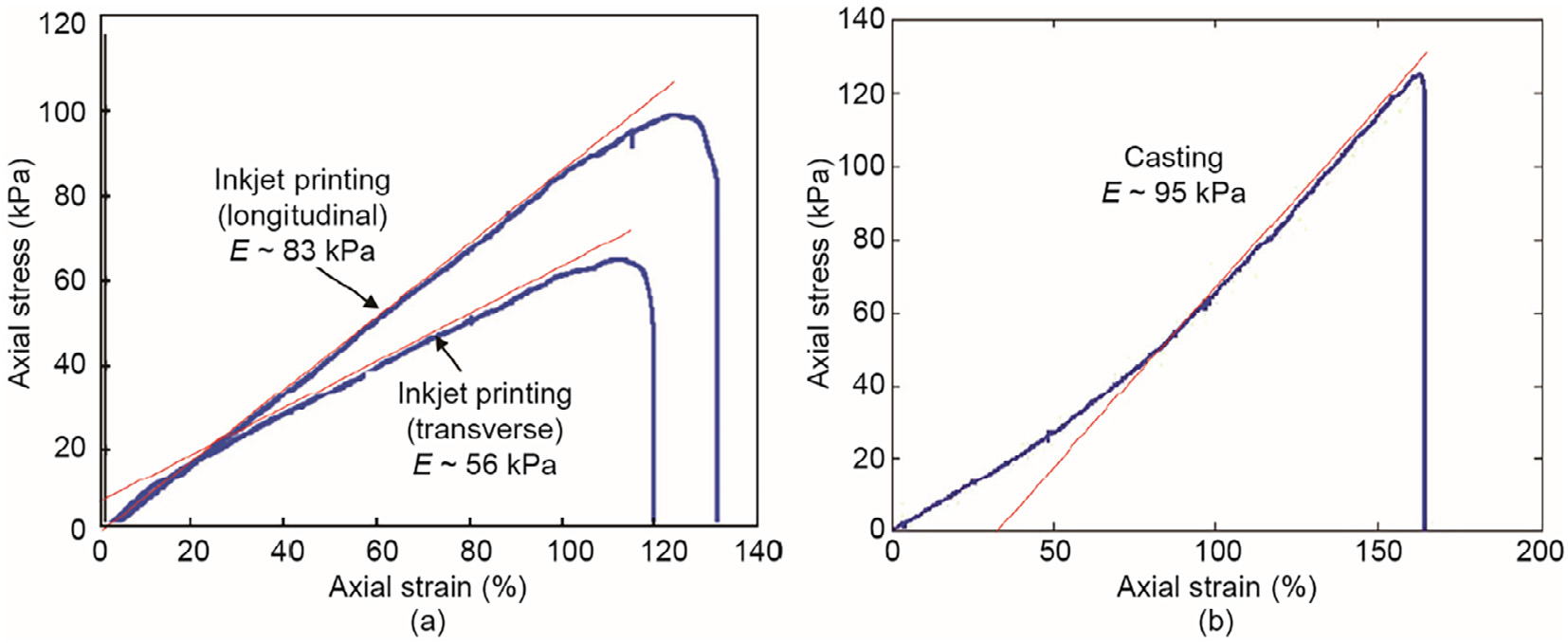
Fig. 2. Representative stress–strain curves for (a) inkjet-printed samples with longitudinal and transverse printing orientations and (b) a casting sample [17]
Conventional mechanical testing methods for AM, including quasi-static tensile testing, compression testing, and needle insertion (indentation), are still widely used to quantify mechanical behavior [17,18]. Digital image correlation (DIC) is also used as an optical method to quantify interfacial deformation. In order to eliminate interfacial features thoroughly, a novel printing-thensolidification AM approach has been developed, which benefits from the yield-stress property of a nano-clay suspension. With this approach, the liquid state and shape of hydrogel structures can be retained during inside-bath printing (with nano-clay as a support bath) [16] or in-air printing (with nano-clay as an internal scaffold) [19], and then solidified simultaneously. The printing efficiency and accuracy of this approach may be investigated further in future.
《4. Predictive models for process-induced surface integrity》4. Predictive models for process-induced surface integrity
An increasing number of research findings are revealing problems with conventional processing; for example, conventional flood cooling during processing may be prejudicial to surface integrity as well as to product life, operator health, and energy consumption. Therefore, sustainable processing is emerging as a relevant field. Sustainable processing of a range of aerospace, automotive, and biomedical alloys can achieve enhanced product quality, life performance, and sustainability, as well as improved process sustainability. Predictive modeling for process-induced surface integrity is of great significance to sustainable machining. The optimal processing parameters, which can be obtained by multiple operations and optimal processing of the model, can be used to realize sustainable machining. Several forward models, both analytic [20–22] and numerical [23,24], have been established in the past decade or more. Forward modeling does not solve the problem of near-infinite iterative experimentation, but merely replaces it with near-infinitive iterative computation. Modeling needs that have been proposed involve hybrid reverse modeling, from product performance to the prediction of process conditions. The desired functional performance would be input as the initial parameter in order to achieve a performance-based product and process prediction design, as shown in Fig. 3 [25]. Reverse modeling is a paradigm shift toward true surface engineering that would enable the production of novel products with unprecedented functional performance and sustainability.
《Fig.3》

Fig. 3. The predictive product design process [25]. PM, M, U, and PU refer to the pre-manufacturing, manufacturing, use, and post-use stages in life-cycle product, respectively.
Physics-based convergent (multidisciplinary) models for the optimization of manufacturing processes should ultimately be process agnostic. Regardless of the manufacturing process, the external thermal, mechanical, and chemical loads that occur during the process cause specific internal material loads such as temperature and stress fields (see Fig. 4, correlation 2 [26]), and thus lead to modification of the material. Based on this knowledge, process signatures have been proposed [27], which link internal material loads with the resulting material modifications, and determine the underlying mechanisms in order to solve the inverse problem and pre-determine the required machining parameters.
《Fig.4》
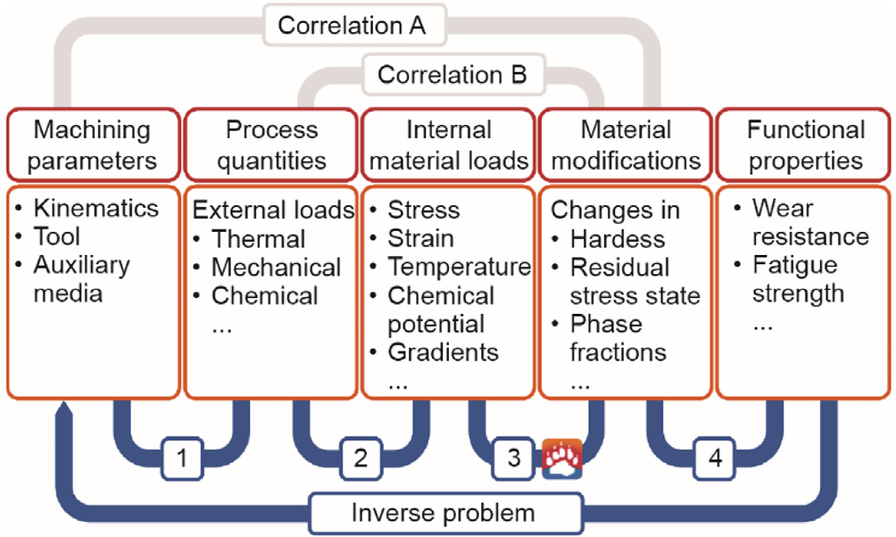
Fig. 4. The causal sequence of manufacturing processes [26].
Thus far, outstanding progress has been achieved in process signatures [27–31]. One prominent result is the uniform notation that has been developed for process signatures and their components. Fig. 5 [26] demonstrates that a process signature includes many Process Signature Components (PSCs) for different scale levels and different types of material modification. For each PSC box, one unified formula M = f(L) is used to embody the correlation between an internal material load (L) and a material modification (M) by involving numerical and analytical models as auxiliary means.
《Fig.5》

Fig. 5. Notation of a process signature with its single component [26].
Once the physics-based correlations are known, use of the knowledge-based approach to predict machining parameters under a desired functional property becomes feasible. In future, underlying mechanisms at the microstructural and polycrystalline level will become a highlight of process signatures. The impacts of the initial material state of a workpiece and of multi-stage processing and process chains are also beginning to attract attention [26].
In order to apply theoretical models or inverse models to guide actual industrial production, more complex situations should be considered in industrial applications. Industrial manufacturing processes cover diversified multiscale and multi-physics industrial problems that require modeling and analysis in order to be flexible. In recent years, applications of ultra-precision products are becoming increasingly extensive; these include various optical lenses and other ultra-precision machining components whose geometrical accuracy can be as precise as 100 nm. Moreover, human hand-held devices, which have a scale of centimeters, take up such a large market share that industry has put a great deal of effort into improving their efficiency while guaranteeing product quality. Therefore, the scale of industrial cases ranges widely, from a centimeter scale to micrometer and nanometer scales. A topdown modeling approach based on multiscale and multi-physics methods has been proposed in order to analyze this kind of industrial ultra-precision multiscale phenomenon [32,33].
To date, multiscale and multi-physics modeling and analysis have been shown to be feasible and have been used in simulations of an aerofoil components manufacturing system. The next level will involve work using digital twins combined with smart machining and intelligent analysis, along with advanced precision machining, which can be a powerful tool for process optimization [34]. Moreover, work with the simulation approach in digital smart machining has been verified by industrial cases and is believed to be capable of improving the ultra-precision machining process.
《5. Conclusions and outlook》
5. Conclusions and outlook
Through reverse modeling, it is possible to establish the relationship between machining parameters and functional performance in order to realize sustainable machining for better environmental friendliness, personnel health, and operational safety, and to achieve low machining cost and waste reduction. Given the current processing methods, the focus should be on controlling and optimizing the influencing factors with the greatest weights, and reflecting them in the model. In a specific machining process, particularly when machining hard and brittle materials, damage suppression for high-speed machining should be taken into account, because the surface roughness increases as the cutting speed of machining increases.
In general, surface integrity covers a wide range of research fields from modeling to metrology, and from manufacturing to process signatures; thus, it is a bridge that combines scientific research with specific applications. Surface integrity has come far beyond its initial concept—which originally focused on the five main areas of surface roughness, micro-hardness, microstructure, residual stress, and features—and is now much more comprehensive in concept than conventional surface metrology. However, no clear definition of surface integrity has been established as yet, so more details must be investigated in order to determine the essential commonalities within this field.
In future work in surface integrity, more attention should be paid to interdisciplinary intersection and the practical needs of industry. Deep integration of manufacturing, measurement, material science, mathematics, and fundamental physics in surface and subsurface research would yield many promising achievements. The use of various processing methods that complement each other, in addition to new technologies, will allow us to further develop surface-integrity-related parameters to meet functional demands.
《Acknowledgements》
Acknowledgements
The CIRP Conference on Surface Integrity (CSI) in 2018 was sponsored by the Chinese Academy of Engineering and the Tianjin Development Programme for International Academic Exchange Platform.


 京公网安备 11010502051620号


