
《1. Introduction 》
1. Introduction
A precise and fast distance-measurement method is necessary in mobile and large-scale dimensional metrology [1,2]. In traditional distance-measurement methods, such as the homodyne or heterodyne methods, a continuous wavelength (CW) laser is used to measure distance or length by accumulating the interferometric phase to achieve a high precision [3]; these methods have been applied in gravitational-wave strain [4]. However, the ambiguity range of this kind of single-wavelength interferometer is only half the wavelength of the used wavelength, and phase accumulation must be consecutive to avoid interruption during measurement. In contrast, light detection and ranging (LIDAR) allows interruption along the beam path and measures distance through pulsed or radio frequency (RF)-modulated waveforms. Although it has a large ambiguity range, the resolution is usually worse than tens of microns. The advent of the optical frequency comb (OFC) as a light source has led to revolutionary progress in ranging and other metrology applications [5–7]. A stable OFC provides narrowlinewidth spectral lines, which serve as a series of CW lasers spaced evenly in the frequency domain. In addition, a stable OFC can potentially accomplish fast measurements due to its repetition rate of hundreds of megahertz, or higher.
Numerous OFC-based ranging systems have been proposed, such as the time-of-flight (TOF) method, which is based on an optical cross-correlation technique [8]; synthetic-wavelength interferometry, which utilizes different optical modes to generate harmonics of an OFC’s repetition rate [9–11] or employs multiple wavelengths referenced to a fully stabilized comb [12,13]; and dispersive interferometry, which involves calculating the phasefrequency slope of the interference spectrum [14–16]. These single-comb-based methods realize absolute distance measurement with certain precision and a relatively simple setup. However, they have not fully leveraged all comb modes, as it is often difficult to distinguish adjacent comb lines with megahertz-togigahertz mode spacing. Therefore, these single-comb-based ranging methods do not combine the advantages of an OFC, which includes high spectral resolution, fast pulse rate, and large ambiguity range. The dual-comb-based ranging (DCR) system solves this problem by using two OFCs with slightly different repetition rates to realize multi-heterodyne spectroscopy and time-resolved interferograms (IGMs) on a comb tooth-by-tooth basis [17]. In other words, the DCR system utilizes about 104 narrow spectral lines to measure distance simultaneously. This dual-comb-based concept provides a unique combination of high precision, high speed, and a large ambiguity range, and has been widely used in absolute distance measurement [18–34]. Although this paper focuses on a dual-comb system applied to distance measurement, the same basic technique has been applied to spectroscopy [35–49], dispersion analysis in long fibers [50], ellipsometry [51], material characterization [52], hyperspectral imaging [53–55], microscopy [56,57], vibrometry [32], and strain sensors [58]. These applications highlight the versatility of the dual-comb system; they have the same underlying dual-comb architecture and confront similar technical challenges [46–49,59–64].
This review is organized as follows: Section 2 provides a basic introduction to TOF-based DCR, including the principles of the system and parameter optimization. To address higher precision, Section 3 introduces synthetic-wavelength interferometry (SWI) and carrier-wave interferometry (CWI) in a DCR system in the absence of phase noise and intensity noise. Actual DCR system must contend with finite linewidths, comb drift, and intensity fluctuations. Section 4 discusses these noise sources and corresponding methods to realize a low-noise DCR. Section 5 concludes by summarizing current progress and future challenges.
《2. TOF-based DCR 》
2. TOF-based DCR
《2.1. Interferograms in time and frequency domains 》
2.1. Interferograms in time and frequency domains
An OFC is a broadband coherent light source consisting of a series of discrete longitudinal optical modes. Each optical mode can be described in terms of repetition rate (fr) and offset frequency (fo) as f(n) = nfr + fo [5,6]. The dual-comb system uses a pair of combs with a slight repetition rate difference; this is also known as linear optical sampling in the time domain and multi-heterodyne spectroscopy in the frequency domain
Fig. 1 shows the DCR system. A pulse train from the signal laser (Comb 1, repetition rate fr1, repetition time Tr1) passes through a Michelson interferometer, generating two pulse trains separated by reflections from the measurement (M) and reference (R) mirrors. Next, the local oscillator (LO) laser (Comb 2, repetition rate fr2, repetition time Tr2), beats with the signal laser. The two combs have a slight repetition rate difference of ∆fr = fr1 - fr2. The light is filtered with an optical spectrum width of ∆υcomb. The detected signal is filtered via a low-pass electronic filter and then digitized and processed. The IGMs are depicted as periodic envelopes multiplied by a carrier wave signal, as illustrated in the time domain and frequency domain.
《Fig.1》

Fig. 1. Simplified image of a DCR system. The pulse train from a signal laser (Comb 1) passes through the Michelson interferometer and then combines with an LO laser (Comb 2). Depending on the configuration, a tunable bandpass filter is employed to satisfy the Nyquist condition. The sampling clock is usually equal to fr2. BS: beam splitter; OBPF: optical bandpass filter; PD: photoelectric detector; LPF: low-pass filter; Tupdate: update time; IR: reference interferograms; IM: measurement interferograms; ∆t: measured time delay; ADC: analog-to-digital converter.
The time-domain description of a DCR system is shown in Fig. 2. Two separate pulse trains with a time delay of ∆τ are sampled linearly by the pulse train from Comb 2 with an effective time step as follows:

《Fig.2》

Fig. 2. Time-domain description of the DCR system. The signal and LO emit pulse trains with different repetition rates; the relative timing between the signal and the LO pulse proceeds in increments of ∆T with each sequential pulse. As a result, the measured time delay ∆τ is scaled up to ∆t.
This generates IGMs (IR and IM) with a certain update time, Tupdate = m·Tr1 = 1/∆fr, where m = fr1/∆fr and denotes the number of measurement pulses in every Tupdate. The Nyquist sampling limitation requires the optical bandwidth of the combs to satisfy the relationship ∆υcomb < 1/(2∆T). As a result, the measured time delay is amplified as follows: ∆t = m·∆τ, where ∆t is determined by the peaks of the fitted envelopes [19,65]. The distance can be obtained from this TOF information (DTOF), expressed as follows:

where υ is the optical pulse velocity.
In the frequency domain, we can consider the DCR system as a multi-heterodyne spectrometer with massively parallel CW lasers; its output is simply an RF comb, as shown in Fig. 3. The intensity and phase of the detected RF comb teeth are proportional to the product of the electric fields of the two combs. To ensure a oneto-one mapping of the optical modes to the RF modes, it is necessary for ∆υcomb < mfr2/2, where m also denotes the number of modes of Comb 2 for every period in the frequency domain. Thus, the DCR system should strictly satisfy the following condition:

《Fig.3》

Fig. 3. Frequency-domain description of the DCR system. (a) The description of two OFCs; (b) the description of RF comb; (c) the phase information of the RF comb. In (a) and (b), the solid dashed curves indicate the OBPF and electronic LPF applied in the optical and RF domain, respectively. The straight dashed lines indicate the optical comb lines and RF comb lines before using the OBPF and electronic LPF, respectively. fopt: optical frequency; fRF is the radio frequency.
which is equivalent to the Nyquist sampling limitation in the timedomain description. The DCR system generates two RF combs, as depicted above, because the signal-pulse train is divided into two; the main difference between them is the phase spectrum (φR for IR and φM for IM). If we regard the DCR system as dispersive interferometry [14], then the TOF information can also be obtained from the phase-frequency slope as follows: ∆t = d∆φ/(2πdfRF), where ∆φ = φM - φR; fRF is the radio frequency. A detailed demonstration is presented in Section 3.
《2.2. Parameter optimization》
2.2. Parameter optimization
The parameters of the two combs exert a significant impact on the precision of the TOF-based DCR [19,22,24]. A basic condition is that the RF spectrum should be located between 0 and fr2/2, as displayed in Fig. 3. According to the Nyquist condition (Eq. (3)), a smaller ∆fr is preferred to avoid aliasing when fr1, fr2, and ∆υcomb are maintained. Meanwhile, a larger factor of m = fr1/∆fr benefits the low timing jitter (∆τ = ∆t/m); however, the uncertainty analysis of Eq. (2) leads to an opposite result. For simplicity, the DTOF is replaced by D in the relative uncertainty (UD/D) of TOF-based ranging results, expressed as follows:

First, we ignore the pulse velocity uncertainty caused by environmental disturbance; only three parts remain—the uncertainties of ∆t, ∆fr, and fr1 (denoted as u∆t, u∆fr , and ufr1 ). Clearly, a larger ∆fr will decrease the relative uncertainty. Therefore, an optimal ∆fr region should be chosen for TOF-based DCR, as has been demonstrated in experiments and simulations [19,22]. Moreover, the optimal region varies among DCR systems under different degrees of uncertainty.
Second, we prefer a high repetition rate to reduce ufr1 /fr1 and u∆fr /∆fr because we can choose a larger ∆fr if high-repetition-rate combs are available. Therefore, we can improve the ranging precision and measurement rate simultaneously. However, a tradeoff exists between precision, measurement rate, and an ambiguity range equals to υ/(2fr1). High-repetition-rate DCR systems realized by dissipative Kerr soliton (DKS) states in micro-resonator frequency combs [30,31] and electro-optic combs [32–34] usually provide an update rate in megahertz and sub-micron TOF precision with an ambiguity range in millimeters.
Third, a simple calculation method reduces the uncertainty of the time delay, ∆t [27]; the modified time delay can be expressed as follows:

where ∆tRR is the measured time delay between two successive reference IGMs. The common uncertainties of ∆t and ∆tRR are partially removed, thus returning a more stable result.
In summary, the TOF-based DCR can be optimized by adjusting the repetition rate difference, repetition rate, and time-delay calculation method. The precision of TOF results can generally be enhanced to several microns, although results are limited by the intensity noise, to be discussed in Section 4. Regardless of whether intensity noise exists, the precision can be further improved by the application of interferometry in DCR system; see Section 3 for details.
《3. Precision enhancement: Interferometry in DCR》
3. Precision enhancement: Interferometry in DCR
《3.1. Comb phase information 》
3.1. Comb phase information
Fig. 3 shows the frequency-domain principle of DCR, where the phase-frequency slope can be utilized to calculate time delay. In addition, it is possible to obtain a stable phase in all modes. The electric fields of Comb 1 (ER(M), including reference and measurement pulses) and Comb 2 (ELO, LO pulses) are expressed as follows:

where f1(n1) and f2(n2) represent the frequency modes of Combs 1 and 2, respectively; A(n1) and A(n2) are their amplitude, respectively; i is the imaginary symbol. Interference between two electric fields generates reference and measurement IGMs of the following:

where k represents the order of the RF comb mode generated from ER(M)(n1) and ELO (n2); fRF(k) = f1(n1) –f2(n2); * represents for the conjugate complex number. Next, we can calculate the phase difference ∆φ(n1) = φM(n1) - φR(n1) from the RF signal:

Other interferometry can also feasibly be applied, as described below.
《3.2. Synthetic-wavelength interferometry 》
3.2. Synthetic-wavelength interferometry
SWI is an effective bridge ranging approach to improve ranging precision. It has an adjustable ambiguity range and a relatively higher precision than the TOF method; thus, it has been widely applied in single-comb ranging methods [9–13]. Given that the DCR system is a mode-resolved interferometer, it is possible to utilize two modes to build a synthetic wavelength (λsyn), expressed as follows:

where λ1 and λ2 are the wavelengths of two modes with phase ∆φ1 and ∆φ2, respectively. The phase of the synthetic wavelength is φsyn = ∆φ2 - ∆φ1. To address the limited measured optical bandwidth, as shown in Eq. (3), two optical bandpass filters with a different center wavelength can be used to extend the range of the wavelength difference [18]. Thus, a more precise result (Dsyn) can be measured using the synthetic wavelength and its phase, expressed as follows:

where Nsyn is an integer determined by the TOF result DTOF, expressed as follows:

where INT represents the integer conversion identifier. The synthetic wavelength is usually dozens of microns, which can be directly linked with TOF-based results. The precision of the SWI-based ranging result reaches about 1 μm.
《3.3. Carrier-wave interferometry》
3.3. Carrier-wave interferometry
CWI, an extremely precise interferometry, is also applied to DCR system. The principle is the same as a single-wavelength light with a Michelson interferometer that measures distance or length. Instead of accumulating the interferometric phase, the SWI-based ranging result Dsyn is used to determine the multiple integers Nc of the half-carrier wavelength λc/2. In this process, the SWI results should be averaged until the precision is below λc/4. The multiple integer Nc can be expressed as follows:

Finally, an extremely precise result (Dc) can be calculated by the CWI method, as follows:

where φc is the interferometric phase of the carrier wavelength λc; either ∆φ1 and λ1 or ∆φ2 and λ2 can be used.
The process of applying interferometry in DCR system is shown in Fig. 4 [18]. If the measured distance is larger than the ambiguity range of the TOF method (υ/(2fr1)), other methods will be needed to determine an approximate distance value, such as building a synthetic ambiguity range υ/(2∆fr) that reaches about 10 km by changing the comb repetition rate [17,21].
《Fig.4》

Fig. 4. A combination of TOF, SWI, and CWI methods (three waveforms versus distance).
In summary, the DCR system is a powerful ranging tool for the application of a serial ranging method using a smaller hardware increment. The essential requirement for a DCR system is phase information availability, which is difficult to achieve. In the next section, we discuss phase noise and other noises in a DCR system and introduce a current solution for suppressing noise.
《4. Noise analysis and solutions》
4. Noise analysis and solutions
《4.1. Frequency noise, phase noise, and timing jitter》
4.1. Frequency noise, phase noise, and timing jitter
As noted above, a dual-comb interferometer essentially generates an RF comb from an optical comb; therefore, research on the noise of a mode-lock laser is applicable to a dual-comb system [66–69]. In this review paper, we focus on the appearance rather than on the physical essence of laser noise, which enriches our understanding of the tight-locking method and post-correction method.
The repetition rate of an OFC is determined by the equivalent cavity length using fr = υ/L, where L is the cavity length. For simplicity, real-time environmental disturbance induces a relative cavity length change of δL. The instantaneous noise of the repetition rate is δfr(t) = -fr(δL/L), where δL and δfr represent the noise of corresponding variables. The corresponding phase noise is

where τ is integral time; t represents the real time. In addition, the timing jitter of pulses is

In a DCR system, we assume that the phase noise of two combs is combined. As the repetition rate of the RF comb is ∆fr, the timing jitter of IGMs in the DCR system (Tjitter) is

We can measure the timing jitter directly in the time domain, for example by using a balanced optical cross-correlator method [66]. Given the complexity of this approach, an optical heterodyne method is more suitable for use with a dual-comb interferometer [60,70]. The relative phase noise between two comb lines can also be measured; this principle is illustrated in Fig. 5. A CW laser is used as an optical intermediary to obtain a relative beat, fb = f1 - f2. In this case, two combs are fully stabilized to an RF standard to avoid parameter drift, thus allowing for accurate noise measurement. In free-running case, two CW lasers with separated wavelength are needed to distinguish the noise of fo and fr [60,61]. Calculating the instantaneous frequency noise (δfb(t)) of the relative beat is simple. Similar to Eq. (14), the phase noise between two combs’ modes is δφb(t), from which δφr(t) = δφb(t)/n1 can be determined. Note that n1 ≈ n2 if the Dfr is not overly large. Finally, the frequency noise, phase noise, and timing jitter of the DCR system can be measured.
《Fig.5》
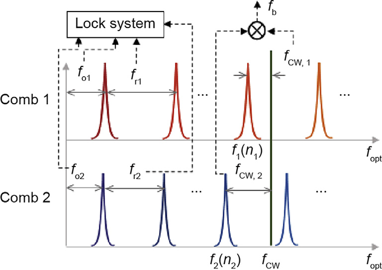
Fig. 5. The principle to generate relative phase noise between two comb lines. Two beat signals between the CW laser and two combs are fCW,1 = fCW - f1(n1), fCW,2 = fCW - f2(n2), and fb = f1(n1) - f2(n2).
Typically, the linewidth of the relative beat fb reaches about 100 kHz with an approximately 104 rad phase fluctuation, and leads to a timing jitter of about 100 ns for IGMs in a fiber-combbased DCR [60]. The linewidth is much wider than the spacing of the RF comb (∆fr), and the phase noise is much larger than 2π. Even for unconventional light-source-based DCR systems with inherent high mutual coherence, such as free-running mode-locked bidirectional dual-comb ring lasers [26,71,72] and electro-optic combs modulated from a single CW laser [32–34,73], a resolved phase has not been achieved. Therefore, noise-suppression methods are required to realize a precise DCR system, as described above.
《4.2. Tight-locking method》
4.2. Tight-locking method
The conventional approach employs two ultra-stable CW lasers as extremely accurate optical references to stabilize fo and fr [17,37,42]. When fo is phase locked by an f–2f interferometer, only one ultra-stable CW laser is enough [51]. Taking Comb 1 in Fig. 5 as an example, the fo1 and fCW,1 should be stabilized; a stable repetition rate will be obtained if the CW laser is referenced to an external ultra-stable cavity. Because high mutual coherence is required in a dual-comb interferometer, an electro-optic modulator-based synchronous locking approach is proposed as an alternative. Specifically, one can either lock fo1, fo2, fr1, fCW,1, and fCW,2 [46] or lock fo1, fo2, fr1, and fb [18,62]. A feedforward relative stabilization [63] is proposed under a similar principle based on an acousto-optic frequency shifter and piezoelectric transducer (PZT). These tight-locking approaches provide a mode-resolved and phase-stable spectrum; however, the high complexity and cost of tight-locking two combs result in extensive challenges for future applications.
《4.3. Post-correction method 》
4.3. Post-correction method
The other approach is called the post-correction method; it continuously monitors parameter fluctuations between the two combs and compensates for the noise of dual-comb IGMs instead of feeding back to the comb sources. Two effective post-correction methods, which are realized via analog signal processing [48,74] and digital signal correction [47,49,61], share the same principle: both use two free-running CW lasers with a separated wavelength as optical intermediaries and obtain two relative beat signals between two combs. These two relative beat signals are enough to characterize the noise of the relative offset frequency and relative repetition rate. It is possible to correct the RF comb’s offset frequency noise because all modes share the same offset frequency. In addition, the difference between two relative beat signals is irrelevant to the fo noise, which can be used to correct the ∆fr noise by reconstructing the IGMs’ time-domain sampling sequence. It would be much simpler if the post-correction were applied to a high-repetition-rate dual-comb system [59], because the two beat signals are obtained directly from the RF comb. Furthermore, even self-corrected spectroscopy can be realized when two combs initially possess high mutual coherence [75]. This suppresses the relative frequency noise between the two combs, which is sufficient to realize mode-resolved spectroscopy.
Stable phase information is also necessary in the DCR system, but has not yet been demonstrated in existing work. In our recent work, we proposed a digital correction method to realize a moderesolved and phase-stable dual-comb interferometer [60,64]. We focused on the phase noise of the carrier wave and timing jitter of the IGMs, where the carrier phase noise is computed from the relative beat fb (Fig. 5), expressed as δφc(t) = δφb(t) · (fc/fCW). The correction algorithm is realized in the time domain and divided into two steps:
First, we simply correct the carrier phase noise:

where I0 is the raw IGM; I1 is the phase-corrected IGM.
Then, we shift the IGMs to compensate for the timing jitter and obtain the phase-timing corrected IGM I2 as:

Finally, we obtain the sub-hertz relative linewidth, a relative timing jitter of about 1 ns, and a 0.2 rad precision in the carrier phase. The post-corrected dual-comb system avoids the experimental challenges associated with high-bandwidth active feedback or feedforward. Furthermore, the digital method economizes some of the RF electronics used in analog adaptive sampling. It is also more powerful, since it can manipulate the noise in digital form and take advantage of modern field-programmable gate arrays.
《4.4. Intensity noise》
4.4. Intensity noise
In addition to the noises introduced above, intensity noise may affect DCR performance. We demonstrate this phenomenon via a simulation that changes the signal-to-noise ratio (SNR) of an IGM in the time domain and estimates its timing jitter and carrier phase jitter. Fig. 6 shows the results when the SNR ranges from 10 to 103 . The carrier phase jitter δφc ∝ SNR caused by the intensity noise is negligible and can be ignored in most cases because the phase jitter is still about 0.1 rad even with a tight-locking [18] or post-correction method [60]. However, the SNR appears to exert a substantial effect on the timing jitter; the simulation revealed a ~1 ns timing jitter when SNR = 40, which concurred with our experimental results [62]. The simulation results also indicated that it is reasonable to maintain the SNR beyond 20. For low-SNR situations, coherent averaging can suppress intensity noise effi- ciently as SNR ∝ T1/2, where T is the coherent averaging time [37,76]. Moreover, when acquiring DCR data over times greater than a few seconds, coherent averaging solves the problem of data overload because it averages IGMs directly in the time domain. Two conditions should be satisfied here: First, the repetition rates of both combs and the difference between their fo frequencies should be integer multiples of ∆fr; second, the carrier phase should be sufficiently stable, which can be realized by the tight-locking method and post-correction method. We utilize the exact value of the carrier phase as determined by the measured distance; therefore, we cannot manually adjust the carrier phase to meet the coherent averaging condition.
《Fig.6》

Fig. 6. Relationship between timing jitter, phase jitter, and SNR, estimated by a simulation.
《5. Conclusion 》
5. Conclusion
In conclusion, an OFC is an ideal source of absolute distance measurement, as it provides fast pulses and a series of discrete optical modes with broad bands. The DCR system fully exploits these properties to measure distance with high precision, a fast rate, and a long ambiguity range. With the development of OFCs, the DCR system will become a flexible, compact tool with the potential to replace traditional ranging tools in laboratory and field applications. A common concern regarding the air refractive index [77] should be considered in DCR in future. In addition, the DCR system could be further combined with other applications that require both optical amplitude and phase information, such as three-dimensional imaging applications [53–57].
《Acknowledgements》
Acknowledgements
This work was supported by the National Natural Science Foundation of China (61575105, 61611140125), Beijing Natural Science Foundation (3182011), and Shenzhen Fundamental Research Funding (JCYJ20170412171535171).
《Compliance with ethics guidelines》
Compliance with ethics guidelines
Zebin Zhu and Guanhao Wu declare that they have no conflict of interest or financial conflicts to disclose.


 京公网安备 11010502051620号


