
《1. Introduction》
1. Introduction
The Hong Kong–Zhuhai–Macao Bridge (HZMB) is located at the Pearl River Estuary on the southeast coast of China; it is the longest as-build marine crossings made of island, tunnel, and bridge. It links Hong Kong in the east with Zhuhai–Macao in the west with a total length of 55 km. The link was built according to the highway standard of six lanes with three lanes going each way; it has a design speed of 100 km·h-1 and a design life of 120 years. The HZMB has improved traffic conditions on the east and west sides of the coast of the Pearl River Estuary and strengthened the communication, transportation, and economic integration of the three regions, thus accelerating the formation of the Guangdong–Hong Kong–Macao Greater Bay Area. This paper introduces the design and construction of the HZMB, with a focus on the new technologies involved in building the artificial islands and immersed tunnel.
《2. Project overview》
2. Project overview
The HZMB main part has a length of 29.6 km (Fig. 1); its regime is generally scoured on the east and sedimented on the west; on the west side bridge with a length of 22.9 km was built (Fig. 2(a)) while on the east side an immersed tunnel with a length of 6.7 km was built in order to reserve the main navigational channel for 3 × 10⁵ t oil tankers and remain within the height clearance limitation from the Hong Kong airport. In order to connect the bridges with both ends of the tunnel, two artificial islands each with a land area of 1 × 10⁵ m2 were built [1,2]. The construction of the HZMB received approval and began in January 2011; it was completed and handed over in February 2018 and opened to traffic in October 2018.
《Fig. 1》
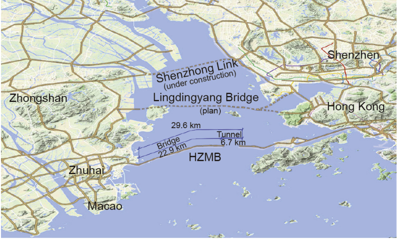
Fig. 1. Geographical and economic environment and overview of the HZMB.
《Fig. 2》
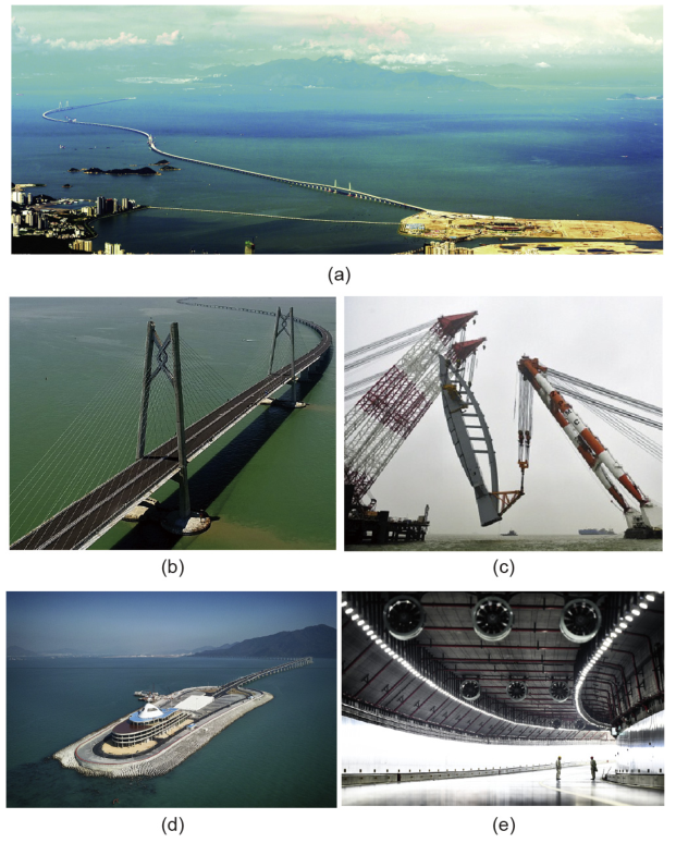
Fig. 2. The main part of the HZMB. (a) Overlook of the bridge section; (b) Qingzhou Bridge, symbolizing a Chinese knot; (c) installation of the dolphin tower on the Jianghai Bridge; (d) east artificial island connecting the tunnel and the bridge; (e) the inner look of the tunnel.
Several novel works were performed in the design and construction of this project, based on a philosophy of upsizing and integration, standardization, factorization, and prefabrication. The bridge and its construction have the following notable characteristics: ① 4 × 10⁵ t of steel was used for the superstructure, thereby breaking a world record; ② the anti-ship-collision ability of the bridge was improved using a steel tube composite structure in the pile foundation; ③ the piers of the non-navigational bridge were prefabricated in the factory and installed in one piece so as to ensure the schedule and safety and better manage the risk; and ④ the towers of the three navigable bridges were designed to symbolize a Chinese knot (Fig. 2(b)), a dolphin, and a wind sail, respectively. In particular, the dolphin tower rises to a height of around 100 m and weighs 2600 t; it was prefabricated and installed in one piece. In combination with the modern construction method, this unique symbol provides the bridge with a strong cultural atmosphere.
The artificial islands and tunnel have the following notable characteristics: ① The work scale was supremely large; and ② the tunnel’s alignment is 20 m below the seabed, and thus set a world record for the deepest buried immersed tunnel. Furthermore, the worksite was in a complex environment that included typhoons, strong convection, flooding in summer, and monsoons in winter; the passing by of over 4000 vessels per day; and the passage of the island tunnel site through the core conservation region for the Chinese white dolphin, which required a very high level of environmental protection. Under these conditions, the underwater foundation, prefabrication, and marine installation of the immersed tunnel, which was over 6 km long, were implemented smoothly. In the following discussion, we introduce the design and construction techniques that were used for the artificial islands and the tunnel.
《3. Rapid and reliable island construction technique》
3. Rapid and reliable island construction technique
To provide the necessary conditions for the connection of the first tunnel element, the artificial islands and the cut and cover section, which was cast in situ on the island, had to be completed first. However, the soft soil stratum under the artificial islands is over 30 m thick; thus, the island construction was projected to take three years, which would leave inadequate time for tunnel construction.
The soft soil in the foundation of the artificial islands had both advantages and disadvantages: On the negative side, it would lead to is a vast amount of work if the conventional island construction method was used—that is, if the soft soil was improved by fully or partially replacing it with sand or stone. On the positive side, the penetrability and impermeability of the soil were advantageous. Therefore, steel cylinders with a diameter of 22 m, height of 50 m, and wall thickness of 1.6 cm were inserted into the ground to a depth of around 30 m. An island ring was formed by inserting 60 cylinders in a contiguous pattern (Fig. 3). Auxiliary cells were used to connect the cylinders, and were inserted into the impermeable ground layer. The cylinders and auxiliary cells formed an impermeable wall, which enabled dewatering inside the ring.
《Fig. 3》
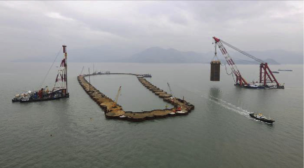
Fig. 3. The last cylinder to form the east island.
The method described above sped up the schedule greatly in the following ways: ① The construction of the temporary island wall was fast. The large size of the steel cylinders resulted in a lower installation time and a shorter time being required for marine work. The procedure governing the timeline became the prefabrication and transportation of the cylinders and auxiliary cells. ② The foundation work was fast. The impermeable walls that were formed by the cylinders permitted sand filling and the placement of vertical drains on the island, in order to achieve a surcharge pre-compression with a high over-consolidated ratio. Hence, a substantial amount of underwater foundation works were eliminated. ③ The cylinders were used as a fence structure for the construction of the tunnel’s cut and cover section, thus eliminating the need to excavate and support an 18 m deep trench on the islands.
By applying this method, we shortened the time required for island formation to seven months. The decreased marine operation reduced the impact on the Chinese white dolphin species and on ship navigation. It is worth mentioning that the cost of the island construction did not outstrip the budget, despite the development, research, and execution of this new method, because the schedule was shortened and the marine work was reduced.
《4. Immersed tunnel》
4. Immersed tunnel
The immersed tunnel consists of 33 tunnel elements and a closure joint. The typical element is 180 m long, 37.95 m wide, and 11.4 m high, and has a mass of 7.6 × 10⁴ t.
《4.1. Composite foundation and facilities development》
4.1. Composite foundation and facilities development
The initial foundation scheme required support piles to start from both ends of the tunnel and gradually change to settlementreducing piles and then to natural foundation in the midsection of the tunnel (Fig. 4(a)). However, in a test for the load performance of the pile cap and gravel bed, the settlement did not converge with the increased loading level. Therefore, the scheme that was implemented involved a composite foundation layer, underwater surcharge, and ground improvement (Fig. 4(b)). Most of the ground improvement was done using sand compaction piles. The composite foundation layer provides a hard base for the tunnel structure, the underwater surcharge provides even settlement along the space, and the ground improvement ensures adequate geological capacity.
《Fig. 4》

Fig. 4. (a) The original foundation scheme; (b) the implemented foundation scheme. PHC: prestressed high-strength concrete pipe pile; SCP: sand compaction pile.
To ensure the quality of the work, a series of special-purpose equipment was developed. A grab dredger was modified with a plane-dredging function in order to reduce the disturbance to the foundation soil and increase the accuracy to a vertical tolerance of ±50 cm on the trench bottom. A dredger was reformed into a ‘‘stamp-placing” type in order to clean the sediment at the trench bottom before the placement of the gravel bed. A stone-compacting and leveling vessel was developed to place the cobble layer as part of the composite foundation layer; this vessel placed and vibrated the cobble mass under the water by means of two falling pipes and one hydraulic hammer. In addition, a gravel-leveling platform was made for the placement of the gravel bed; it was equipped with a suction head to directly remove local sediment on the gravel bed, almost without disturbing the gravel that had been placed in position.
《4.2. Robust semi-rigid element》
4.2. Robust semi-rigid element
Eventually, over 20 m of thick sediment will cover the tunnel roof. In future, part of this sediment will be re-dredged in order to update the depth of the navigation channel. The longitudinal structure of the type of tunnel element that was considered, which includes a monolithic element and segmented element [3], cannot withstand such a high overload of sediment soil.
Two load-reduction solutions were proposed: The first was maintenance dredging to remove the sediment; the second involved pre-placing light material above the tunnel. Both solutions would require immense effort. Therefore, we opted not to change the environment, but rather to change the tunnel structure itself, as a semi-rigid element [4] could be used to increase the robustness of the longitudinal structure of the element. As an analogy, if a monolithic element is compared to a muscled person and a segmented element is compared to a flexible person, then a semi-rigid element would have both strength and flexibility. The implementation of this structure greatly reduced the marine works. The main change in the tunnel element structure involved keeping the temporary pre-stressing for permanent use, instead of releasing it after the installation was complete.
《4.3. Conscientious memory bearing》
4.3. Conscientious memory bearing
Although the use of a semi-rigid element secured the safety of the tunnel elements, the joints between the elements would be the tunnel’s weakness. The vertical locking of the joints was by post-assembled steel shear keys. Although delaying the locking time could reduce the stress on the shear key, over 20 m of sediment soil will gradually load up on the tunnel roof during the in-service period, causing high stress of the shear keys or their adjacent parts. In particular, this could lead to the cracking of the concrete on the external wall, resulting in corrosion issues. Therefore, memory bearing was developed to protect these joints [5]. For example, as shown in Fig. 5, the bearing ‘‘remembers” the capacity of the shear key in question; once the memorized value is about to be exceeded by the load, the bearing can divert the excess part of the load to the foundation below the sunken vessel (R1 in Fig. 5) rather than to the foundation of the adjacent structure via the shear key (R2 in Fig. 5). In this way, memory bearing can free the structure to enact its maximum utility without damaging itself. The tearing and fracture testing of special-purpose materials can be performed in order to obtain the character of the bearing.
《Fig. 5》

Fig. 5. The function of the memory bearing. δ: The compression of the bearing, is equal to the vertical offset of the two tunnel elements, provided there is no rotation; G: Submerged weight of the sunken ship; F: force conveyed by the memory bearing; h: height of the memory bearing.
Strengthening the structure usually compensates for the geological uncertainty. However, the size of an immersed tunnel often limits its structural capacity; therefore, the safety level of the element joint could be insufficient. Memory bearing compensates for this risk and shifts the risk to one of redundancy of the structural safety.
《4.4. Deployable closure joint》
4.4. Deployable closure joint
The closure joint is located between tunnel elements E29 and E30, where the bottom elevation is -27.9 m, and where the construction work is exposed to waves and current. The existing methods for the closure joint of an immersed tunnel are the cofferdam, panel, V-block, terminal block, and key element [6] methods. All of these methods use hydrostatic pressure or grouting for connection and waterstopping; in other words, these methods are passive. We developed a positive connection and waterstop technique for the closure joint [7]. The closure joint was constructed as an integral element. During towing and immersion, its dimensions were less than those of its final state. During connection, the joint stretched itself longitudinally until it came into contact with the adjacent elements. The application of this method shortened the marine work from more than six months to just three days.
《4.5. The factory system for tunnel element production》
4.5. The factory system for tunnel element production
Appropriate site selection for the tunnel element prefabrication yard was essential in order to save time and cost. We compared six locations around the site and finally chose an abandoned quarry yard on Guishan Island that was nearest to the tunnel site. The factory method [8] was used to produce the 33 tunnel elements. The factory occupied a land area of 5.6 × 10⁵ m2 and was divided into production (Fig. 6), management, and living zones. A staff of 1200 was involved.
《Fig. 6》

Fig. 6. The layout of the tunnel element prefabrication yard.
To align with the installation schedule, which required the production of one element per month depending on weather and marine conditions, we produced two elements every two months by means of two production lines. The critical path on the production line involved rebar assembly, formwork, and concrete casting; of these, rebar assembly was the governing procedure. Therefore, rebar assembly was further discretized into three parts in the production line—the assembly of the slab, the walls, and the roof—in order to achieve a smooth line.
The tunnel’s wall is 1.5 m thick. Each segment was cast in one pour with a volume of 3400 m3 . Zero cast cracking of nearly 1 × 10⁶ m3 concrete was realized using a natural and standard environment cracking-control scheme, including a full-section simultaneous casting method.
《4.6. Accurate installation of tunnel elements》
4.6. Accurate installation of tunnel elements
The tunnel elements were transported in a constraint channel [9]; however, if this were to go out of control, not only would the project suffer a significant loss, but also the stranded element would become an obstacle to the busy marine traffic. To reduce this risk, more than ten boats escorted the transportation. A total of 12 tugboats were employed to tow the tunnel elements (Fig. 7). Among these, four tugboats were connected to the element (two fore and two aft); the remaining eight tugboats sailed alongside in order to control the position of the element by pushing on the immersion rigs riding above the element when a large cross current was present. For towing safety, we developed a navigation piloting system and monitored the position of the element and all tugboats in real time. These data were displayed on the screen in the command room on the immersion rig as well as on all the tugboats. In this way, the chief captain in the command room was able to give explicit and real-time orders to the other tugboat captains. Nevertheless, it was a challenge for the chief captain, who had a considerable amount of offshore towing experience, to order 12 tugboats simultaneously in order to keep a 7.6 × 10⁴ t element on track. Hence, before the real towing occurred, we carried out barge-towing exercises four times.
《Fig. 7》

Fig. 7. Transportation of E30, the last element installed.
The tunnel trench was 30 m deep, and this depth caused two severe problems: ① The current velocity at the trench bottom was sometimes higher than that at the sea surface, which led to an unexpected transverse offset of 10 cm when installing element E10; and ② the sediment rate was fast, such that even a single day’s worth of sediment disabled the installation [10]. Two times, while element E15 was on its way to the site, unexpectedly thick sediment covers were observed halfway there, and the element had to turn back. It was not until the third time that we succeed in installing this element. The solution to the first problem was to develop a forecasting and alert system for the connection; the solution to the second problem was to develop a forecasting and alert system for the sedimentation and to enact specialized sediment-cleaning equipment.
《5. Closing remarks》
5. Closing remarks
After the invasion of the extremely severe Typhoon Haiyan in the South Pacific in 2013, we optimized the project’s hazard design and comprehensively increased the site’s hazard-prevention capability. The site withstood the trials of the strong typhoons Hato and Mangkhut.
We insisted on a methodology of testing and validation before work was carried out. The island tunnel contractor carried out more than 140 tests, including testing of the sediment-accommodating mechanism and capabilities of the gravel, testing of the frictional coefficient of the concrete and gravel, and testing of the fast towing [11]. Zero tunnel leakage was achieved from the installation of E1 in May 2013 until the time of writing this paper. A total of 33 elements underwent 35 installations with no major accidents.
In parallel with the HZMB, several mega-scaled bridges are under construction in the south-east of China, such as the Wufengshan and Lutongjiang Highway and Rail Bridges in Jiangsu Province, the Pingtan Strait Highway–Railway Bridge in Fujian Province, and the Second Humen Bridge and Shenzhong Link in the Pearl River Estuary. In future, more mega-projects will be undertaken, including the Qiongzhou Strait Crossing to Hainan Province, the Dalian–Yantai Link in the Bohai Strait, and the Taiwan Strait Tunnel. The construction of these projects will present increasingly difficult and complex engineering problems, and will thus open up a new era of bridge-tunnel engineering science and technology in China.
《Appendix A. Supplementary material》
Appendix A. Supplementary material
Supplementary data associated with this article can be found, in the online version, at http://dx.doi.org/10.1016/j.eng.2018.11.002.


 京公网安备 11010502051620号


