
《1. Introduction》
1. Introduction
Tungsten (W) has attracted a great deal of attention in the fields of industry, national defense, and the military due to its useful properties, which include its high melting point (3422 °C), low coefficient of thermal expansion, and excellent oxidation resistance [1]. Recently, W has been widely used in weapons and high-speed steel, such as rocket thruster nozzles and armorpiercing shells. The engineering field places higher requirements on the performance and structural complexity of pure W materials. However, pure W powders generally exhibit the problems of poor spreading ability and inherent embrittlement during traditional manufacturing processes, which impede their engineering applications. Microstructural factors are the primary causes for the embrittlement and low ductility of W material [2]. Therefore, homogenization of the grain structure and decrease of the grain size can considerably enhance the ductility [3]. The microstructure changes commonly when the heating temperature exceeds the recrystallization temperature, although this further weakens the strength and results in embrittlement [4]. However, the brittleness of W material can be decreased by adding ceramics [5]. At higher operating temperatures, the migration of the grain boundary and grain growth can be impeded when ceramic nanoparticles are uniformly distributed, resulting in a reduction of the brittleness [6].
Powder metallurgy (PM), such as sintering by hot-press and spark plasma, is a common way to fabricate W-based components. Their high melting temperatures and restricted densification ability cause W-based materials to form a residual porosity when the working temperatures of PM processes are limited. Moreover, pretreatments to fabricate the required shapes of certain special tools are imperative [7]. Owing to the large van der Waals attractive forces, the nanoscale particles of W-based components tend to agglomerate, resulting in heterogeneous microstructures and the coarsening of ultrafine nanostructures by PM processing. The differential stresses generate the spreading of interior cracks, which are caused by the microstructural inhomogeneity in PM-processed components. Hence, in order to obtain W alloys components with homogeneous microstructures and excellent performance, it is important to find new processing approaches.
Selective laser melting (SLM), a recently developed additive manufacturing approach using powdered materials, can produce components with complex geometries that are difficult to produce by means of conventional fabrication techniques [8–11]. Zhang et al. [12] produced biomedical beta titanium (Ti)-based parts such as the elaborate acetabular cup, thus demonstrating the capability of SLM to manufacture complex structures. On the outer surface of the cup, there is a complicated, refined scaffold structure for osseointegration modification. Zhang and Attar [13] reported several tools and devices that were produced by making use of the uniqueness of the SLM technique, including an accurate acetabular Ti-based cup. Song et al. [14] developed a manufacturing method for nanocomposite parts with a complex structure, and studied the effect of Cr3C2 particles on iron matrix composites in order to obtain better mechanical properties. SLM is a form of net-shape production, and it has many benefits, including processing flexibility and wide applicability. During SLM processes, a high power density and a superfast heating/cooling rate can be reached. Therefore, SLM is an effective way to manufacture high-meltingtemperature W-based components, as it can cause metal powders to melt completely and solidify quickly. However, W have many issues related to the high stresses that are induced by the shrinkage and subsequent severe cracks that occur during liquid–solid transformation. Control of the microstructure in SLM is a major problem. The incomplete melting and poor spreading ability that result from the high melting temperature of W powders make it difficult to obtain a continuous and regular scanning track and without balling. Furthermore, the component performance strongly depends on the properties of the scanning track. As a result, it is necessary to increase the energy input appropriately in order to ensure that the W powder is melted completely [15]. Yadroitsev et al. [16,17] analyzed the roles of scanning speed and energy density in the stability of the scanning track, and reported that a low scanning speed can result in an unstable track. In addition, scanning speed has an effect on the geometry of the molten pool (i.e., the track width, remelted depth, and contact angle), which is utilized to optimize the parameters and form regular scanning tracks. Aboulkhair et al. [18] researched the effect of scanning speed on the formation of single tracks, and examined keyhole mode control and the relationship between the hardness distributions across melt pools and the chemical composition. Shi et al. [19] developed regression models to predict the geometric characteristics of single tracks. However, the powder-to-laser absorptivity and underlying absorption behavior of pure W material have not been investigated.
Raising the absorptivity is an extraordinarily effective way to increase the laser energy input (when the power density is limited by the laser performance). The measurement of powder-to-laser absorptivity is the basis for research on the laser absorption of materials. Using experimental methods, studies have been carried out to measure absorptivity. Representative measurement methods include the integrating sphere method and calorimetry. Tolochko et al. [20] reported the absorptivity of single/twocomponent powders measured by a sphere integrator, and the numerical wave of metal powder absorptivity during laser processing. Use of the integrating sphere method to measure transmitted and reflected irradiation from powder layers and to estimate the attenuation coefficients has been proposed by McVey et al. [21]. Regarding calorimetry, Rubenchik et al. [22] designed a calorimetric model to measure the powder-to-laser absorptivity of different powder materials by changing the particle size distributions and thicknesses. However, direct experimental measurements are extremely time-consuming and limited. Similarly, it is difficult to obtain the spatial distribution of the absorbed radiation. These considerations have accelerated the development of the numerical investigation approach. Boley et al. [23] used a ray-tracing simulation to calculate the absorptivity of metal powder. The size distribution and geometry of the metal powder were found to be the decisive factors in determining the absorptivity, and the significance of multiple scattering has been emphasized. However, quantitative characterization in the absorptivity calculation of pure W powder, including the radiation distribution and mechanism, has not been analyzed.
To calculate the absorptivity of pure W material and to simulate laser radiation transfer in W powder layers, a laser absorption model was developed. To achieve a high laser absorptivity for pure W materials in order to reduce the energy input requirement, the absorptivity and distribution of the absorbed irradiance were studied. The influence of the diameter of W particles on the radiation absorption and deposited irradiance patterns was determined, with the aim of optimizing the irradiation behavior according to the laser absorption. In addition, through a scanning track experiment using W powder, the spreading ability and wettability of different particle sizes were studied. The accuracy of the simulation was verified by comparing experimental results with the results of the ray-tracking simulation.
《2. Modeling setup and governing equations》
2. Modeling setup and governing equations
《2.1. Theoretical basis of optics》
2.1. Theoretical basis of optics
When a laser beam strikes powder layers during SLM, it causes three physical phenomena: reflection (R), absorption (A), and transmission (T). Based on the mechanism of ray propagation, the relationship between the three values is as follows:

The relationship between the radiant intensities of the reflection ray  and the incident ray
  is as follows:

where  is the reflectivity.
Laser irradiation onto the powder layer generates the above three phenomena, causing the laser radiation to diminish progressively as it is absorbed. When a powder particle is assumed to be an ideal sphere, the absorptivity and particle packing determine the value of the energy input in regards to the powder layers; which is quantitatively expressed as the porosity  and particle diameter
  , respectively. The optical extinction coefficient
  is as follows [24]:

where  .The optical thickness
  [25] is given by the following:

where  is the height in the space consists of spherical particles.
Within the powder layer, attenuation of the laser intensity can be described as exponential decay named the Beer–Lambert Law [26]. The latter represents the intensity of the transmitted radiation as follows:
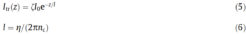
where  is the distance from the substrate surface;
  is the absorption rate;
  is the wavelength;
  is the absorption length; and nc is the real part of the complex refractive index. Tolochko et al. [20] showed that the absorption length is usually 10–1000 nm for the laser wavelengths of interest. The absorption length is negligible compared with the powder radius; thus, the value of the transmitted radiation
  can be regarded as zero—that is, the transmitted radiation is completely absorbed by the powder. Eq. (1) can be simplified to the following:

When a beam strikes the powder material at a certain angle  , the absorptivity of S polarization
  and P polarization
  are given by the Fresnel formulas [27]:

where n is the complex refractive index of the material. Under normal conditions, polarization refers to the combined action of S and P.
《2.2. Modeling》
2.2. Modeling
In order to calculate the energy absorptivity and study the irradiation distribution in a porous powder layer, a laser absorption model based on ray tracing was established. The decay of the reflected radiation is exponential in the ray-tracing calculation model, which can apply to pure W powder. The following hypotheses are indispensable in the simulation model: Each individual powder particle is a perfect sphere and the arrangement of a powder layer is a hexagonal close-packed structure.
In a collection of tens of thousands of rays, the polarization, power, and reflection/refraction of each ray must be tracked. To simulation ray tracing, a model was established using the unconventional optical software FRED. The simulation model (including the powder layer, laser beam, and substrate) and the laser propagation in the powder layers are shown in Fig. 1(a). Gusarov et al. [28] proposed a common laser absorption model; the laser radiation transfer in model is shown in Fig. 1(b). The powders, consisting of single-sized spheres, were placed on the substrate in a dense arrangement. The dimension of the substrate was a fixed value (400 μm × 200 μm × 50 μm). The diameters of powder particles was set to be a constant in one powder bed, then it changed according to the calculation requirements in different groups of powder beds. Under the actual conditions, the region of powder spreading was a square with the same area in different groups of powder beds. The 1/e2 radius of the Gaussian beam and the laser energy input were 35 μm and 1 W, respectively. Absorptivity calculations were performed for the substrate and powder layers.
《Fig. 1》

Fig. 1. (a) Physical model of the powder layer, laser beam, and substrate; (b) laser radiation transfer in a powder layer on a substrate.  : incident power density;
  : powder layer height;
  : radiation propagation angle;
  : radiation intensity.
《3. Experimental procedure》
3. Experimental procedure
《3.1. Powder preparation》
3.1. Powder preparation
The powder used in this experiment was W powder of 99.9% purity with spherical particles. The powder was divided into five groups according to the mean particle size. Different sieves were used to filter the powders, such that the particle size intervals were < 10 μm, 10–18 μm, 18–25 μm, 25–38 μm, and > 38 μm. Fig. 2(a) shows the powder morphology using a Quanta FEG 250 field emission scanning electron microscope (FE-SEM). The powder particle size distribution was measured using a laser diffraction particle size analyzer (BT-9300H). Five groups of the powdered material were respectively spread on five identical stainless steel substrates.
《Fig. 2》
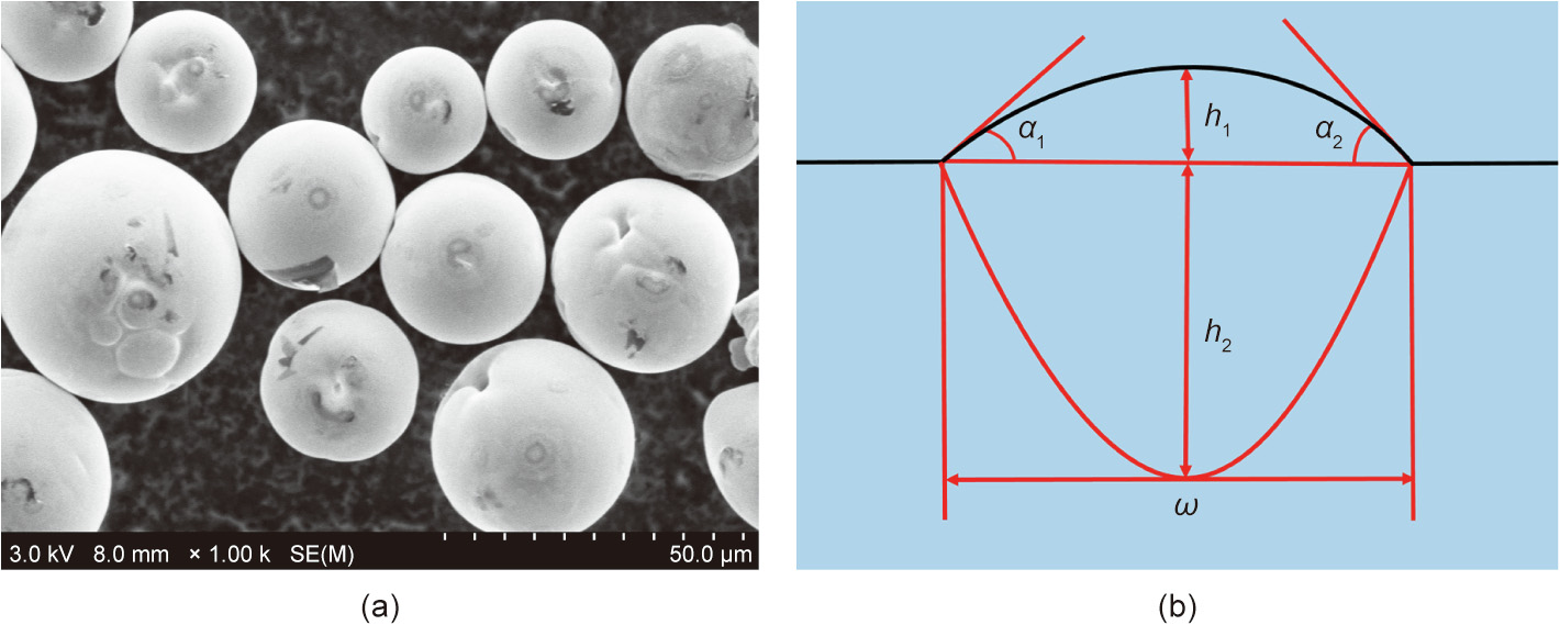
Fig. 2. (a) Characteristic morphologies of W powders in an FE-SEM image; (b) geometric characteristics of the SLM track cross-section.  : width of the tracks;
  : height of the tracks;
  : remelted depth.
《3.2. SLM processing》
3.2. SLM processing
The SLM apparatus was composed of a YLR-500 ytterbium fiber laser with a maximum power of 500 W, an automatic powderlayering device, a processing chamber, inner gas protection, and a computer system. Aside from the powder particle size, the processing parameters remained the same. The parameter optimization was designed to form a satisfactory scanning track. For the SLM of the W material, the laser power was set at 350 W and the scan speed was set at 200 mm·s-1 . The dimensions of the substrate used in this experiment were 15 × 15 cm2 . A micron-sized scale was used for the simulation, however, with the aim of reducing the number of powder particles on the substrate in order to lessen the burden of the calculation simulation.
《3.3. Characterization of scanning tracks》
3.3. Characterization of scanning tracks
FE-SEM was used to characterize the surface morphologies of the scanning tracks. After wire-electrode cutting, the scanning tracks were ground, polished, and etched with a solution composed of an HCl (30 mL)-to-HNO3 (10 mL) volume ratio of 3:1 for 15 s according to the metallographic procedures. For crosssectional geometric characteristic analysis, optical microscopy was used. Fig. 2(b) shows the geometric features of the SLM tracks, including the width of the tracks (), height of the tracks (), remelted depth (), and contact angle (α) obtained by (α1 + α2)/2. The data of the scanning tracks were recorded and placed in a chart.
《4. Results and discussion》
4. Results and discussion
《4.1. Absorptivity and multiple refraction》
4.1. Absorptivity and multiple refraction
To explain the effect of multiple refraction, the absorptivity was calculated for different particle sizes. Due to the function of the incident angle, the complex refractive index was n = 3.0629 + 3.78i at a wavelength of 1.064μlm. The laser beam provided perpendicular illumination and generated a complex interaction with powder layer, as shown in Fig. 3(a). A ray was tracked from one surface to another. In the calculation process, absorption and reflection occurred synchronously. Each ray had a definite power in each polarization state, and the direction of the laser ray varied with the physical absorption reaction. The energy of the laser ray changed according to the above mentioned phenomenon; that is, the radiant intensity of the reflection ray declined due to the Fresnel absorption. After the ray reacted with the system, the ray either struck a neighboring surface or left the model. In the former case, the energy of the refractive ray was absorbed by the powder or substrate, and this part of the energy was not tracked. As a result, the power of the ray decreased after every reflection. The system continued to propagate the ray until the radiation energy was lower than 0.1%. In the latter case, the ray was no longer followed and captured by the external analysis surface. In this situation, the ray entered into the gas environment in the SLM process and did not return to the system. In Fig. 3(b), the increase in the number of rays is related to the enhancement of multiple reflection among powders with a small particle size.
《Fig. 3》
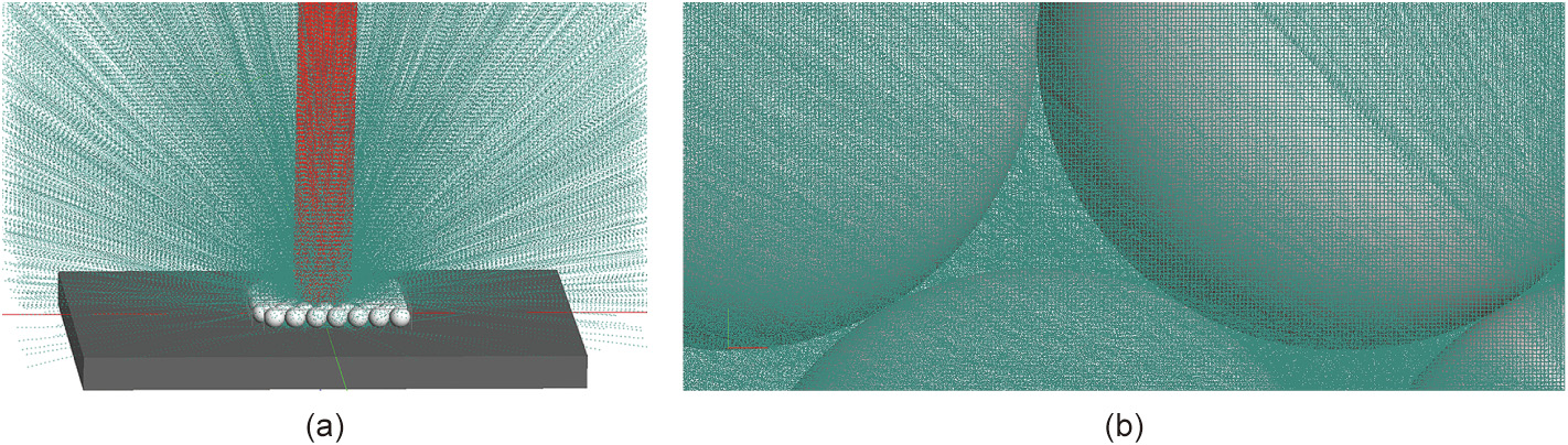
Fig. 3. (a) The laser beam is perpendicular to the powder layers and is scattered to the external environment (the red ray is incident light and the green ray is reflected light); (b) multiple scattering occurs from spherical surfaces. Detail of the ray trajectories is shown.
Fig. 4 shows the calculated laser energy absorptivity of the ray-tracing model with a particle diameter range of 5–45 μm. The curve shows that the powder layer absorptivity diminished as the particle size increased. For particles with a diameter of 5 μm, the absorptivity of the powder layer reached a maximum value of 0.6030. This value dropped slightly to 0.6028 for a particle diameter of 15 μm, indicating that the diameter of the particles has a slight effect on absorption when the particle size is less than 15 μm. With a further increase in particle size to 25 μm, the powder layer absorptivity diminished dramatically to 0.5615. The absorptivity of the powder layers diminished slightly to 0.4986 when the particle size was greater than 25μm. This decrease was mainly due to the weakening of multiple reflections—that is, more rays were reflected to the protective atmosphere while fewer rays penetrated to the powder layers. The absorptivity of all the isolated powder particles without substrate diminished successively from 0.53 for particles with a diameter of 5 lm to 0.45 for particles with a diameter of 45 μm; the absorptivity value of the combined absorption of the isolated powder particles was clearly lower than that of the powder layers for the same case. In addition, the calculated absorptivity of a flat surface was 0.4. These findings further verify that the absorption irradiance within the powder layer considerably exceeded the value of the combined absorption of the isolated powder particles or a flat material. This enhancement of the absorptivity of the powder layers is caused by multiple scattering, which produces additional absorption. In comparison with the case of a dense flat surface, most of the incident energy is trapped in the particle gap between the powder layers, strengthening the interaction of neighboring powder particles.
《Fig. 4》
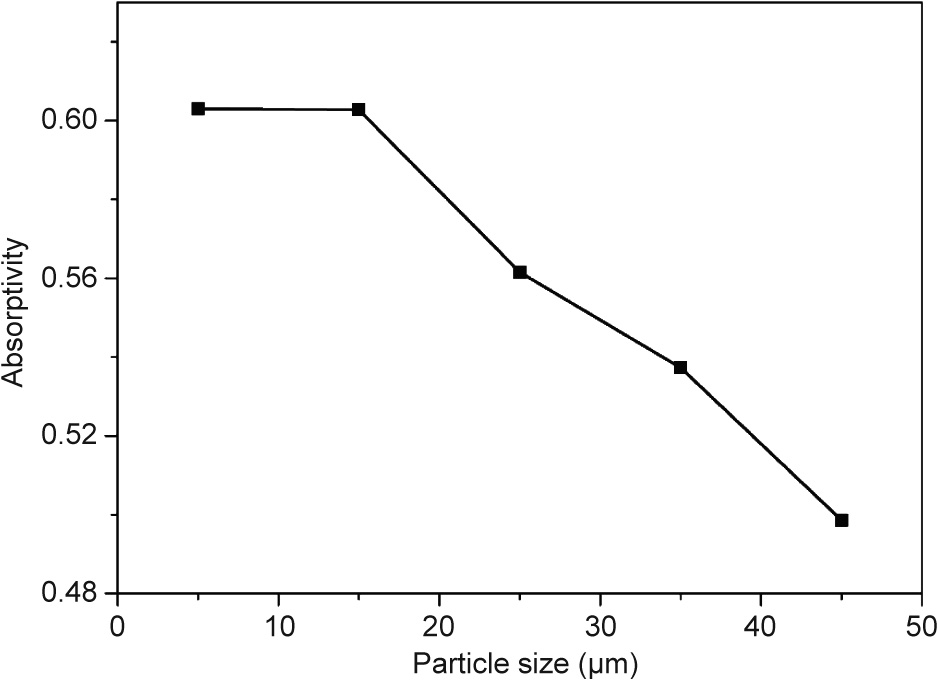
Fig. 4. Absorptivity of the powder layer for five different particle sizes from 5 to 45 μm.
《4.2. Influence of particle size on irradiated energy》
4.2. Influence of particle size on irradiated energy
In the simulation, both the absorptivity of the powder layer and the spatial distribution of the irradiated energy are disclosed. Fig. 5 shows the distribution of the absorbed energy irradiance within the powder layer from the vertical view, which indicates the variation of the absorbed irradiance from the center to the marginal area of the laser beam. The larger the particle size, the fewer powder particles can be irradiated by the laser beam. The irradiance intensity is inhomogeneously distributed on the powder particles, resulting in a decrease of the laser irradiance. Irradiance is a crucial physical quantity in evaluating the properties of laser radiation. It was found that the actual irradiation area decreased with increasing particle size, as shown in Figs. 5(a–e), which limited the absorbed irradiance obtained in the powder array. This result illustrates the rationality of the negative correlation between absorptivity and powder particle size. Moreover, in comparison with the area at the margins of the laser action, the absorbed irradiance in the central area seems to be higher. As the powder particles are arrayed outward, the irradiation appears to abate. Particles that are further from the central zone are seldom or never irradiated. However, this rule requires further quantitative data in order to be proven.
《Fig. 5》
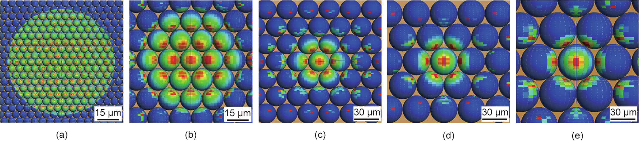
Fig. 5. Absorbed irradiance of powder layers with five different powder sizes: (a) 5 μm; (b) 15 μm; (c) 25 μm; (d) 35 μm; and (e) 45 μm.
《4.3. Distribution of absorbed irradiance》
4.3. Distribution of absorbed irradiance
In order to explain the mechanism of absorption irradiance in more detail, this simulation quantitatively examined the effect of radial distance and azimuthal angle on the absorption irradiance of the powders. A detector was set for each powder, and the irradiation flux on each powder surface was calculated in the simulation. Since the particles of the powder layer were set in an array, a powder particle was always present at the center of the array. This central powder particle was set as the starting point for the radial direction. Certain representative powder particles were selected in order to calculate the irradiance of the particle surface in the outward direction of the radius. In the calculation, the corresponding powder particles were named using the X value of the powder center; the Y and Z values of the coordinates of the selected powder particles remained the same.
First, we chose a particle size of 5 lm as the research object and set the coordinates of the powder center at X1 = 0 μm, X2 = 10 μm, X3 = 20 μm, and X4 = 30 μm to calculate the irradiance. The maximum irradiance value of the powder particle surface was 7.25 × 10⁻⁴, 5.63 × 10⁻⁴, 1.90 × 10⁻⁴, and 3.68 × 10⁻⁵ W·μm–2, respectively. The variation in the powder surface irradiance with the position and azimuthal angle is shown in Fig. 6. The irradiance was continuously distributed according to the azimuthal angle on the surface of each particle. At the position X1 = 0 μm, the absorption irradiation attained its maximum due to the combination of direct laser beam radiation and radiation from neighboring particles. As the radial distance increased, the effect of the direct laser beam weakened, while energy deposition mainly resulted from the multiple reflections, resulting in a decrease of the irradiance value. Furthermore, as the azimuthal angle changed from -180° to 180°, the irradiance first increased and then decreased. This finding means that the absorption irradiance was greater near the point that was directly illuminated by the laser beam. It is worth noting that there was a valley at specific angles, as shown in Fig. 6. This phenomenon was due to the presence of small, densely packed pores when the particle size was set at 5 μm. When the azimuth reached a certain angle, it was difficult for the laser beam to pass through the powder particles into the interspaces; thus, the majority of the first and second reflected rays left the system rather than undergoing multiple scattering, eventually leading to a regional decrease in irradiance. However, the overall irradiance of the 5 μm powder layer was still greater than that of the layers with larger particle sizes.
《Fig. 6》
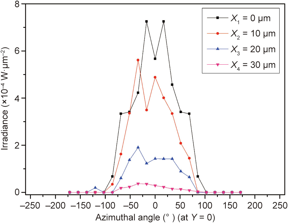
Fig. 6. Powder particle surface irradiance of W at different positions versus the azimuthal axis for a particle diameter of 5 μm. As the position changes, the variation in irradiance is represented by lines of different colors. The irradiance is smaller when the powder particle is further from the center.
Fig. 7 shows the irradiation distribution for four different powder sizes, and vividly demonstrates the variation in the irradiance contour. Depicting the irradiation contour and the intensity of powder particles in the irradiated area at different positions to be clearly seen. Regardless of the particle size, the irradiance decreased from the center to the margin in all cases, generating an even dispersion of the distorted contour (irradiation was not uniformly distributed on the powder surface). The surface irradiance distribution of the particles underwent an evolution from a symmetrical pattern with one peak (the center area), to an inconsistent pattern with the irradiance area obviously decreasing (middle area), to an unsymmetrical pattern with a dispersive irradiance area (marginal area). For the different particle sizes (15–45 μm), the effect of the radial distance and azimuthal angle on irradiation distribution remained generally the same as described above. The intensity of the irradiation distribution changed when the volume of a single pore increased with the increase of particle size. As the particle size increased, the general trend was that the irradiation from the powder layers decreased and the contour of the irradiation gradually contracted. The distribution of irradiation on the central powder particle was homogeneous when the particle size was set to 15 μm, as shown in Fig. 7(a). Due to the multiple reflections, there was energy deposition at various angles and an increase of irradiance. With an increase in particle size, the shrinkage in the area of the deposition of irradiation resulted in a minimum irradiance at a particle size of 45 μm, as shown in Fig. 7(d). Due to the weakness of the multiple reflections, the primary irradiation source of the powder layer was the incident laser rays. As the particle diameter increased, and the volume of the pores of the powder layers increased, there was less opportunity for the ray to interact with the powder particles in the hexagonal closepacked model; thus, a smaller density of ray intensity accumulated on the surface. The incident rays tended to run out of the interspaces into the surrounding environment through multiple scattering. Fig. 8 shows the maximum irradiance of the powder layer for particles with a diameter range of 5–45 μm. The maximum irradiance decreased from 1.117×10⁻³ to 8.5 ×10⁻⁴ W·μm–2 as the particle size increased from 5 to 45 μm. The change in maximum irradiance is consistent with the irradiance variation of the central powder particle for different particle size (5–45 μm), and this is because the maximum irradiance is achieved at the center.
《Fig. 7》
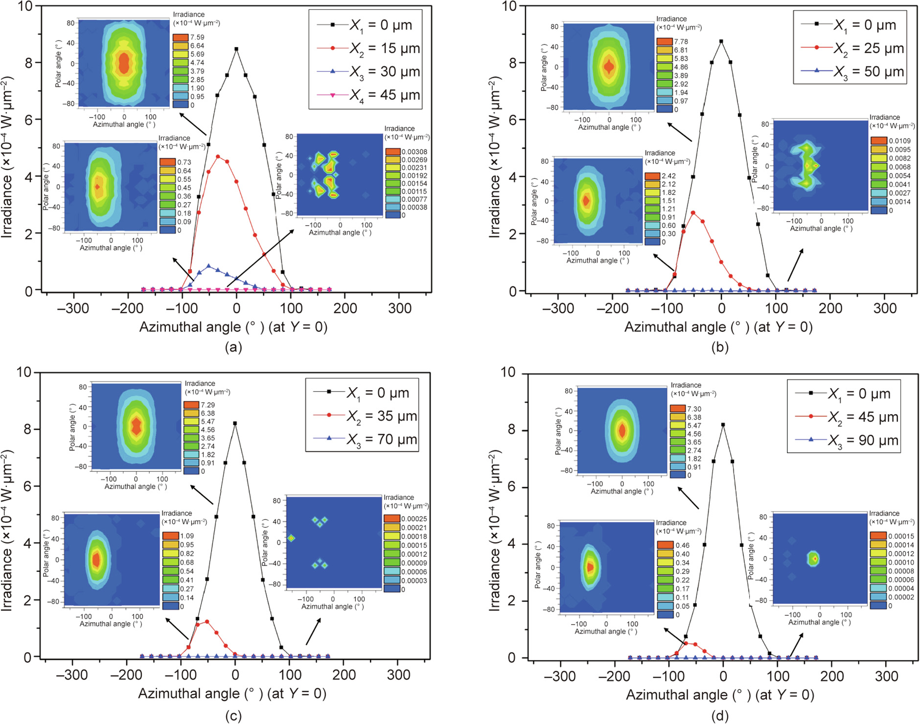
Fig. 7. Calculated surface irradiance of W powder bed versus the azimuthal angle. The effect of the radial distance on irradiation distribution and the contour of irradiation distribution can be observed for four different powder sizes: (a) 15 μm; (b) 25 μm; (c) 35 μm; and (d) 45 μm.
《Fig. 8》

Fig. 8. Maximum irradiance of the powder layer for five different particle sizes from 5 to 45 μm.
《4.4. Effect of particle size on the processing ability of the laser scanning track》
4.4. Effect of particle size on the processing ability of the laser scanning track
This simulation of pure W material obtained an optimized particle size for high absorptivity; this finding was useful for studying the scanning track in SLM. The performance of the SLM-fabricated components strongly depends on the processing ability of the scanning track. By examining the scanning track characteristics— namely, surface morphology and geometry—the contribution of the particle size of W powders to the SLM-fabricated scanning track can be determined. The diameter of the powder particles used in the real-life experiment was 5.7, 16.52, 22.47, 37.26, and 47.63 μm, respectively. Characterization of the scanning track was used to verify the role of the diameter of the W powder particles in the powder-to-laser absorptivity. Furthermore, the optimal particle size to obtain a continuous, stable, and regular scanning track was determined.
Due to the gradient of the surface tension and temperature in the transient melt pool, intense Marangoni flows are formed when the laser beam interacts with the powder layer [29]. Liu et al. [30] reported that a difference in the microstructure and element distribution of SLM-fabricated aluminum alloy resulted from the gradient of surface tension and temperature, which influenced the mechanical properties (i.e., causing a reduction in the micro-hardness and wear resistance from the top surface to the interior). In order to understand the relationship between the particle size distribution and scanning track characteristics, it is necessary to investigate the dynamic parameters of the molten pool behavior, such as surface tension and dynamic viscosity, during the SLM process.
The relationship between surface tension  and temperature can be written as follows [31]:

where T is the operating temperature and Tm is the melting point of W. When T exceeds Tm, the surface tension increases with a decrease of the operating temperature.
The dynamic viscosity  of the melt can be determined by the following equation [32]:

where  is the mass of the atom and
  represents the Boltzmann constant. Eq. (11) indicates that the viscosity of the liquid increases with a low flow velocity and a relatively high surface tension at a low operating temperature.
The convective Marangoni flow intensity can be described by the Marangoni number (Ma) [33]:

where  is the temperature gradient;
  is the linear size of the pool; and
  is the coefficient of thermal diffusion. A low temperature gradient generates a decreased surface tension gradient, hence leading to a decrease of the Marangoni flow intensity.
The surface morphology of the scanning track for different particle sizes is shown in Fig. 9. It is clear that the morphology of different melt tracks displays significant differences at various particle sizes. When the powder diameter is 5.7 μm, Fig. 9(a) shows that the scanning track is continuous and regular without balling or cracks. The continuous melt track surface is smooth, indicating its good liquidity. Based on the previous simulation, the maximum absorptivity of the powder layers can lead to the highest operating temperature and the lowest viscosity of the melt pool, which greatly contribute to the liquidity of the scanning track. As the internal porosity can be suppressed, a high densification of the SLM-fabricated parts can be obtained accordingly. As the particle size increased to 16.52 μm, the scanning track displayed almost no change. When the particle size increased to 22.47 μm at lower energy absorptivity, an irregular scanning track with cracks occurred, as shown in Fig. 9(b). The powder-to-laser absorptivity began to decrease, which is equivalent to the reduction in the operative T.
《Fig. 9》

Fig. 9. Morphology of the scanning track surface of W powder on a stainless steel substrate for different particle sizes: (a)  = 5.7 μm; (b) = 22.47 μm; (c) = 37.26 μm; and (d) = 47.63 μm. Partial magnified details are shown in the insets. refers to the particle size having a cumulative particle size distribution percentage of 50%.
Eq. (10) reveals that c can increase when the working temperature decreases notably. Furthermore, Eq. (11) indicates that a lower T and higher  can lead to an enhancement of the dynamic viscosity, thereby decreasing the Marangoni intensity (Eq. (12)). In this condition, the fluidity of the molten metal was diminished, impeding the penetration of the melt into the powder layers and eventually causing the formation of an irregular track. In addition, the lower absorption and temperature resulted in a decreasing size of the melt pool. Therefore, the conversion time of the metal from liquid to solid was relatively short. During the SLM process, crack formation is related to a high temperature gradient and to residual stresses. The release of residual stress can cause the formation of cracking. In addition, the metallurgical characteristics of the W— low-temperature brittleness and low fracture toughness—accelerate crack growth. As the particle size increased to 37.26 μm, discontinuous melt tracks occurred, as can be observed in Fig. 9(c). At the same time, there was a noticeable splashing around the track, which was caused by the eruption of gas bubbles arising from the molten metal. Fig. 9(d) shows that irregularities and discontinuities appeared when the particle size increased to 47.63 μm; balling also appeared, probably because of the low absorption. Balling is commonly reported as a surface defect; other surface defects include satellites, and there are conspicuous distinctions between balling and satellites [34]. In balling, the ball is not separate from the substrate surface but is rather a solidified modality of the surface; in satellite formation, the satellite results from powder remelting or spattering during the processes of solidification—that is, the temperature is not high enough to make the satellite return to the molten pool. The insets in Fig. 9 visually demonstrate that an increase in particle size promotes irregularity of the scanning track.
The measurements of the melt pool are shown in Fig. 10, which presents the track width, height, remelted depth, and contact angle of the SLM-processed scanning tracks for different particle sizes and indicates the negative relationship between the melt volume and particle size. In general, the track width decreased with an increase in particle size from 5.7 μm up to 47.63 μm, as shown in Fig. 10(a). The highest value of the scanning track width was observed to be 200 μm when the diameter was 5.7 μm, and the lowest value was 165 μm when the diameter was 47.63 μm. The height of the scanning track increased with the increase of particle size, whereas the remelted depth decreased with the increase of particle size, as shown in Figs. 10(b) and (c). On the one hand, the powder layer thickness determined the height of the SLM scanning track, which varies depending on the morphology characteristics of the powder, substrate roughness, and so on. The scanning track showed an average height of about 45 μm with a coefficient of variation of 3.26%. On the other hand, the remelting depth is a significant parameter in determining the processing character of the SLM components. Fig. 10(c) implies that a further increase in particle size might lead to poor bonding of the melting track with the substrate when the balling effect is present. The wetting angle reflects the ability of the scanning track to spread on the substrate and follows Tanner’s law, as discussed by de Gennes [35]. The contact angle of the powder particles increased from about 43° to 51° with the increase of particle size, as shown in Fig. 10(d). The augmentation in the curvature of the surface of the molten metal and the contact angle, which is derived from the thermocapillary phenomena, led to the Rayleigh–Plateau capillary instability. When the particle size was 5.7 μm, the experimental result demonstrated that powder layers with high absorption result in good wettability with no balling on the surface of the scanning track.
《Fig. 10》
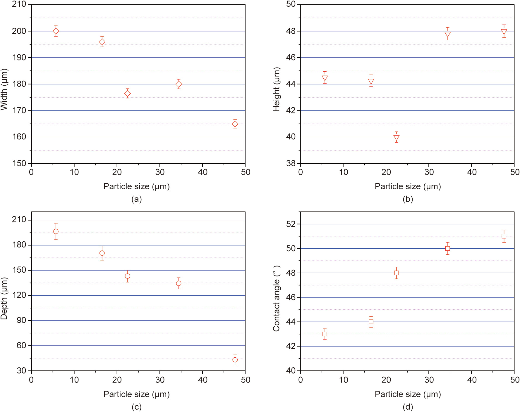
Fig. 10. Geometric characteristics of the scanning tracks versus five particle sizes: (a) track width; (b) track height; (c) remelted depth; and (d) contact angle.
《5. Conclusions》
5. Conclusions
A laser absorption model was presented here in order to study the coupled interaction between the laser beam and the powder particles. The effect of the powder particle size on the powderto-laser absorptivity and distribution of the absorbed irradiance was investigated using ray-tracing calculation. Scanning track experiments were applied to verify the effect of the powder particle size on the laser absorptivity. The main conclusions are summarized as follows:
(1) The powder layer absorptivity diminished with increasing particle size (i.e., the powder-to-laser absorptivity diminished from 0.6030 to 0.4986 when the particle diameter increased from 5 to 45 μm). The absorptivity of powder bed was considerably higher than that of isolated powder particles without a substrate, and higher than the absorptivity of a flat material. The presence of multiple reflections strengthened the interaction between the neighboring particles, and considerably promoted the absorption.
(2) With the increase in particle size, the lesser powder particles were irradiated, the more inhomogeneous the irradiance intensity distributed on the powders was, with the corresponding value of the intensity decreasing.
(3) The value of the absorbed irradiance from the center to the marginal area of the laser beam decreased with increasing particle size. The effect of the direct laser beam was weakened, while energy deposition only resulted from the multiple reflections. In addition, there was a maximum irradiance as the azimuthal angle changed from –180° to 180°.
(4) Characterization of SLM-fabricated scanning tracks was conducted to investigate the surface morphology and geometric characteristics of the fabricated W material. Different particle sizes led to variation in the melt pool size by influencing the Marangoni flow. The high absorption of powders with small particle sizes caused the scanning track to be more continuous and regular.
《Acknowledgements》
Acknowledgements
The authors gratefully acknowledge financial support from the Science Challenge Project (TZ2018006-0301-02 and TZ2018006- 0303-03).
《Compliance with ethics guidelines》
Compliance with ethics guidelines
Jiayao Zhang, Dongdong Gu, Ying Yang, Hongmei Zhang, Hongyu Chen, Donghuai Dai, and Kaijie Lin declare that they have no conflict of interest or financial conflicts to disclose.


 京公网安备 11010502051620号


