
《1. Introduction》
1. Introduction
Amorphous Sm–Co thin films with uniaxial in-plane anisotropy have great potential for application in information storage [1] and spintronics [2]. To be specific, the high coercivity of such thin films ensures high density storage, the lesser grain boundaries in the amorphous state ensure a high signal-to-noise ratio, and the smoothness of the film surface makes contact magnetic recording possible. Furthermore, the uniaxial in-plane anisotropy allows a good recording performance [1]. To date, the magnetic properties [1,3–6]—especially the anisotropy [2,7–11]—of amorphous Sm–Co thin films have been studied extensively. It has been found that various factors can affect the in-plane anisotropy, such as composition [9], film thickness [1], growth temperature [3,7], and pressure [10]; nevertheless, the most effective method to produce uniaxial in-plane anisotropy is to apply an in-plane magnetic field during deposition [2]. Nanoscale amorphous Sm–Co thin films are usually prepared through magnetron sputtering deposition [2,5,6,11] due to the advantages of this method, which include a high rate of film formation, easy control over conditions, and idealized film composition. During sputtering, the role of the magnetic field provided by the magnets behind the target is to control the moving path of the electrons; this magnetic field is approximately 400–800 Oe (1 Oe = 79.6 A·m-1 ) around the erosion track and decays to zero at a distance less than 60 mm. The magnetic field has no influence on the deposition of film, given that the distance from the substrate to the target (130 mm in this paper) is much greater than the scope of 60 mm. Thus, it is usually necessary to install an additional magnet next to the substrate [2] in order to realize uniaxial in-plane magnetic anisotropy in amorphous Sm–Co thin films. This method inevitably requires a more complex setup. Hence, finding a new way to obtain uniaxial in-plane anisotropy without an applied magnetic field remains as an important challenge.
It is notable that the amorphous Sm–Co thin films reported in the literature were mainly grown on amorphous [7] or polycrystal [8–10] substrates. There have also been a few cases involving the use of single-crystal substrates [2,5,6], but a buffer of amorphous layer was usually introduced to allow the amorphous growth of Sm–Co thin films. Accordingly, the growth environment provided by the substrate or buffer layer in previous studies was mainly isotropic. Here, we report the growth of amorphous Sm–Co thin films with uniaxial in-plane anisotropy on (011)-oriented single-crystal substrates. The anisotropic strain, which comes from the difference in lattice constants  along the two in-plane directions, leads to the possibly preferential seeding and growth of ferromagnetic (FM) domains and hence to in-plane magnetic anisotropy of the amorphous Sm–Co thin films. The anisotropy constant can be tunablewith variation of the lattice parameters of the substrates due to the possibly directional pair ordering caused by the local environment.
《2. Material and methods》
2. Material and methods
Amorphous Sm–Co thin films with a thickness of 50 nm were deposited by means of magnetron sputtering onto anisotropic (011)-oriented LaAlO3 (LAO), SrTiO3 (STO), and Pb(Mg1/3Nb2/3) O3–0.3PbTiO3 (PMN–PT) substrates, and onto isotropic (001)- oriented LAO and STO substrates ( = 3.792 Å,
  = 3.905 Å,
  = 4.017 Å) in an argon (Ar) atmosphere. The base pressure was less than 10-6 Pa, and the dimensions of the commercial substrate were 5 mm × 5 mm. A Sm–Co target with a samarium (Sm) concentration of 18 at% was used to obtain the film. In this context, the term anisotropic means that for (011)-oriented substrates, the lattice parameters along the two in-plane directions are different—that is,
 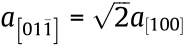 ; hence, an anisotropic growth environment can be provided. The term isotropic in this context indicates that the lattice parameters along the in-plane [100] and [010] directions are equivalent for (001)-oriented substrates. A 50 nm thick capping layer of chromium (Cr) was deposited to protect the amorphous Sm–Co layer from oxidation. The exact thickness of each layer was determined by the deposition rate and the growth time. The thickness of different materials at different sputtering powers and different sputtering pressures was measured by the step meter, and the deposition rate was calculated. The deposition times of the Sm–Co layer and Cr layer were 4 min 34 s and 9 min, respectively. During sputtering, the operated Ar pressures of the Sm–Co layer and Cr layer were 0.45 and 0.35 Pa, respectively. A direct current (DC) sputtering power of 100 and 70 W was used for the Sm–Co layer and the Cr layer, respectively. The substrate-to-target distance was fixed at about 130 mm. A commercial Cr target with a thickness of 6 mm and a SmCo5 target made in-house with a thickness of 5 mm were used in our experiment. Both targets were 60 mm in diameter. All of the films were fabricated at room temperature, and no magnetic field was applied during deposition. The structure of the films was identified by X-ray diffraction (XRD) and gracing-incidence Xray diffraction (GIXRD) using Cu-Kα radiation, and the magnetic properties were determined by the Quantum Design superconducting quantum interference devices (SQUID-VSM). The initial magnetization curves were measured after alternating current (AC) demagnetization. The composition of the films was analyzed by energy dispersive X-ray spectrometric microanalysis (EDX). The obtained Sm and cobalt (Co) concentrations in the Sm–Co film were about 23 at% and 77 at%, respectively. The small deviation of the compositions from the target was probably due to the different deposition rates of the Sm and Co elements.
《3. Results and discussion》
3. Results and discussion
《3.1. Analysis of structure》
3.1. Analysis of structure
Fig. 1 shows a sketch of the heterostructure and the representative directions of the x, y, and z axes in differently oriented substrates. As shown in the figure, there is no buffer layer between the substrate and the Sm–Co layer, which guarantees the direct transference of the strain from the substrate to the films. As a representative display, the XRD patterns of the films grown on STO(011) and LAO(011) are shown in Figs. 2(a) and (b), respectively. There are no stray peaks aside from the peaks from the substrates, which implies that the films are in an amorphous state with no impurity phases. GIXRD was also collected in order to confirm the amorphicity of the Sm–Co films; the results for the corresponding films are shown in Figs. 2(c) and (d), respectively. No peak is visible in the samples grown on the STO(011) and LAO(011) substrates. The absence of the crystal peak indicates the amorphicity of the Sm– Co films, and the lack of the typical broad peak is related to the Sm content. Previous research [2] has demonstrated that the broad peak increases in width with an increase of the Sm content, and will be invisible when the Sm content is high enough. It should be noted that the XRD patterns shown here were selected arbitrarily; all of the films demonstrated the amorphous nature to a similar degree.
《Fig. 1》
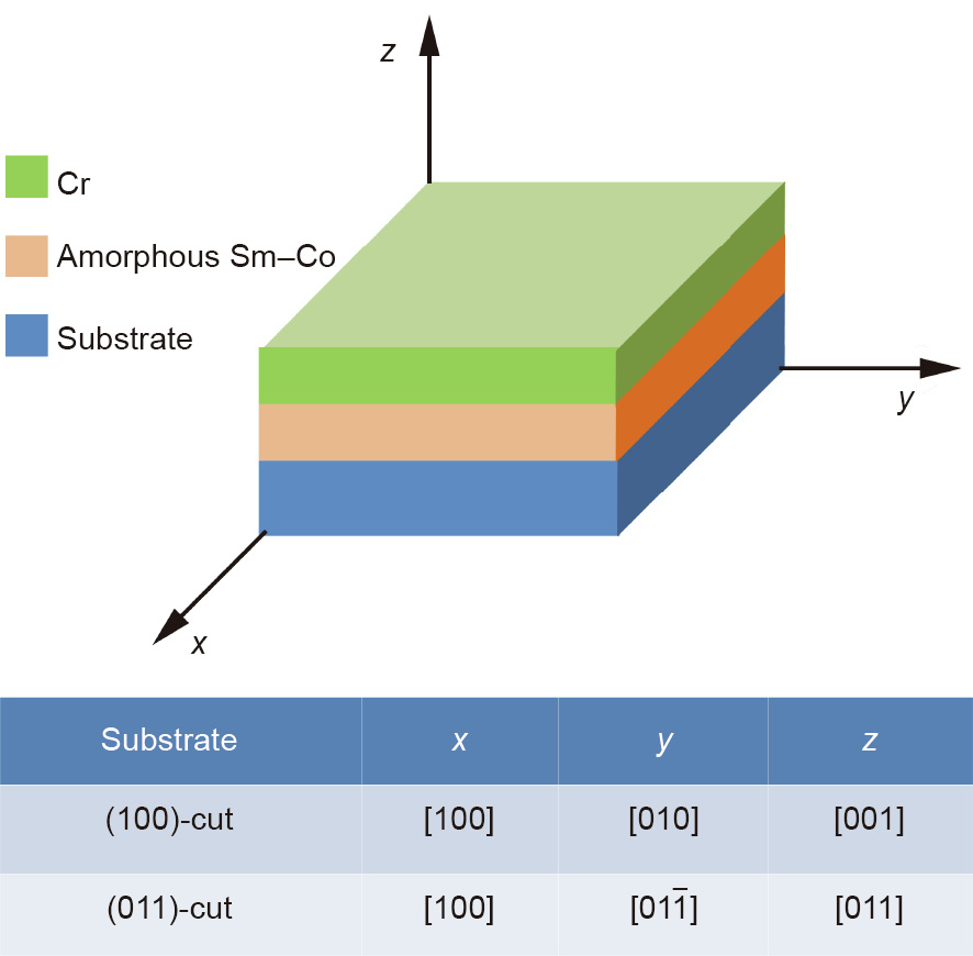
Fig. 1. Sketch of the Cr/amorphous Sm–Co/substrate heterostructure.
《Fig. 2》
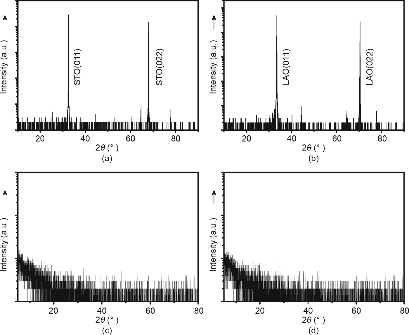
Fig. 2. XRD patterns of the films grown on (a) STO(011) and (b) LAO(011), and GIXRD patterns of the films grown on (c) STO(011) and (d) LAO(011), where a logarithmic scale was adopted for the y axis.
《3.2. Analysis of composition》
3.2. Analysis of composition
The sample has two layers, a Sm–Co layer and a Cr layer, each with a thickness of 50 nm. Cross-sectional scanning electron microscopy (SEM) images are shown in Fig. 3. The images in Figs. 3 (a) and (b) were taken from different areas of the same sample. Since the sample was not placed completely vertically, the surface can be seen in addition to the interface and the substrate. It is clear that the film surface is quite smooth, while the cross-section of the substrate is corrugated. The latter is due to the “breaking off” action during the preparation process. The thickness of the film is about 100 nm in total. The boundary between the two layers (i.e., the Sm–Co layer and Cr layer) cannot be clearly seen, probably due to the amorphous nature of both layers, given that they were both deposited at room temperature.
《Fig. 3》

Fig. 3. Cross-sectional SEM images of (a) one arbitrary point and (b) another arbitrary point of the same sample.
The exact chemical composition of the multilayer film was measured by EDX. Several points were randomly selected at positions close to the substrate in the cross-section of the film. The Sm and Co contents corresponding to different measuring points are listed in Table 1. It was found that the ratios of the Sm and Co elements did not change much among different points. The average Sm and Co concentrations in the film were about 23 at% and 77 at%, respectively, which roughly align with the nominal composition of the target SmCo5. The small deviation of the compositions from the target was probably due to the different deposition rate of Sm and Co elements.
《Table 1》
Table 1 Chemical composition of Sm–Co film measured at randomly selected points near the substrate by means of EDX.

《3.3. Analysis of anisotropy》
3.3. Analysis of anisotropy
Figs. 4(a–c) illustrate the hysteresis loops of the Cr(50 nm)/ amorphous Sm–Co(50 nm) films grown on (011)-oriented PMN– PT, STO, and LAO, respectively, measured with a magnetic field along the in-plane [100] and  directions (H//[100] and H// . It is notable that the squareness ratio of the hysteresis loops along the in-plane direction is much better and the corresponding coercive field is relatively lower than those along the in-plane [100] direction. Furthermore, the remanent magnetization along the direction is obviously higher than that along the [100] direction. In other words, the amorphous Sm–Co films grown on the (011)-cut substrates are obviously magnetic anisotropic. The easy axis of magnetization is along the direction, and the hard axis lies in the [100] direction. A similar phenomenon has also been observed in amorphous Co40Fe40B20 grown on PMN–PT(011) [12]. As mentioned above, for the (011)-oriented single-crystal substrates, the lattice constants along the two in-plane directions were different—namely,
  . For example,
  was approximately equal to 5.363 Å, while
  was approximately equal to 3.792 Å for the LAO(011) substrate. Thus, for the (011)-oriented substrates, anisotropic strain would be brought about by the difference in lattice constants along the two in-plane directions. It is reasonable to expect the anisotropic residual strain to lead to preferential seeding and growth of FM domains; hence, in-plane magnetic anisotropy appears in the amorphous Sm–Co films.
《Fig. 4》

Fig. 4. Hysteresis loops of the amorphous Sm–Co films grown on (a) PMN–PT(011), (b) STO(011), and (c) LAO(011), and initial M–H curves of the amorphous Sm–Co films grown on (d) PMN–PT(011), (e) STO(011), and (f) LAO(011). Emu: electromagnetic unit; M : magnetization; MS: saturation magnetization; H : magnetic field.
Previous studies have indicated that the strain environment provided by substrates can significantly affect the growth of FM domains [13–15]. Ward et al. [13] demonstrated that the ferromagnetic-metal (FMM) domains in La5/8-xPrxCa3/8MnO3 (x = 0.3) film grown on a NdGaO3(101) substrate tend to elongate along the direction with greater tensile strain. Hence, the easy magnetization axis lies in the relatively longer in-plane direction due to the static anisotropy strain field provided by the NdGaO3(101) substrate. Later on, Zhao et al. [14] found that the in-plane anisotropy strain field dynamically promoted by the electric field can enhance the in-plane magnetic anisotropy in (011)- Pr0.7Sr0.3MnO3/PMN–PT. For the (011)-cut PMN–PT substrate, the in-plane long axis is further elongated, while the short axis [100] is compressed as an electric field is applied along the outplane [011] direction. As a result, the in-plane magnetic anisotropy of Pr0.7Sr0.3MnO3 is promoted due to the further preferential growth of FM domains along the direction with tensile strain. Using magnetic force microscopy, Zhou et al. [15] directly observed the strip-shape preferential growth of the domains in La0.67Ca0.33MnO3/NdGaO3(001), where the high orthorhombicity of the substrate supplies in-plane anisotropic strain, and strongly favors the growth of FMM domains along the longer axis. Specifically, in our case, the lattice parameter along the direction of the (011)-oriented LAO, STO, and PMN–PT substrates is just the longer one. Hence, the FM domains preferentially seed and elongate along the direction, and the easy axis lies in this direction. This vital fact indicates that the effect of the anisotropic strain provided by the (011)-oriented single-crystal substrates is essential for the occurrence of uniaxial in-plane anisotropy in amorphous Sm–Co films.
On the basis of the initial M–H curves (i.e., magnetization M as a function of magnetic field H ) illustrated in Figs. 4(d–f), we obtained the anisotropy constants (kA) of the amorphous Sm–Co films deposited onto different substrates according to the following formula:

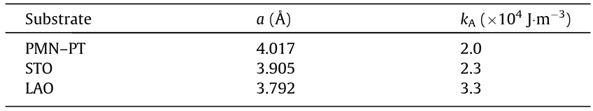
where MiH/MiE represents the initial magnetization along the inplane hard/easy axis, and H represents the in-plane magnetic field. This formula is normally used to calculate the kA of films [9]. The results are listed in Table 2. Every initial M–H curve was successfully measured after AC demagnetization to zero. As the lattice parameter of the substrate decreased, the kA of the corresponding films increased. In particular, the anisotropy constant of the amorphous Sm–Co film grown on the (011)-oriented LAO reached a value as high as kA≈ 3.3 × 10⁴ J·m-3 . Here, it should be noted that there are several routes to approach kA besides Eq. (1), such as the following [8,9]:
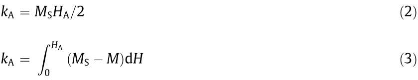
where MS represents the saturation magnetization and HA is the in-plane anisotropy field. In Eqs. (2) and (3), the acquisition of HA is necessary for the computation of kA. However, the HA value is determined by extrapolating from the origin to the saturation along the middle of the hard axis. This is applicable for cases in which the M–H curve has a fully square hysteresis loop along the easy axis, which is not the case in the present work. In Eq. (1), kA is determined from the area enclosed between the initial M–H curves of the easy and hard axes, which is appropriate for our case. Table 2 provides the kA results of the Sm–Co films, which vary on different substrates.
《Table 2》
Table 2 Lattice parameters of the substrates and the corresponding anisotropic constant of amorphous Sm–Co films grown on (011)-cut substrates.
The different kA can be understood by considering the Sm–Co, Co–Co directional pair ordering, which can also be the physical origin of the in-plane anisotropy of amorphous films, according to the literature [10,16,17]. Corb et al. [17] demonstrated that the structural short-range order in Co80Nb14B6 amorphous alloys can build clusters with different symmetries and anisotropies, such as near-trigonal symmetry with high local magnetic anisotropy, and near-octahedral symmetry with low local magnetic anisotropy, crucially depending on the growth environments and temperature. These factors affect atomic diffusion and nucleation. Moreover, Suran et al. [16] reported that the probability of the occurrence of specific clusters also depends on the growth pressures, and the kA value varies with the sputtering pressure. Specific to our samples, local anisotropy may be produced due to the formation of various clusters, where the structural short-range ordering—that is, the Sm–Co, Co–Co directional pair ordering—depends on the local environments provided by different substrates. Clusters with trigonal-like/octahedral-like symmetry (high/low local magnetic anisotropy) may be easy to form when the lattice parameter of the slab is relatively small/large, such as LAO/PMN–PT. Furthermore, the strain field provided by the substrate may also play a role in the orientation of clusters, thus ensuring that the total energy acting on the film reaches a minimum. It is also possible that the trigonal-like clusters in all the films are the main part, and the probability of the occurrence of trigonal-like clusters increases with the decrement of the lattice parameter of the substrate, given the different local environments provided by the slabs. Thus, this reasoning explains why the kA was enhanced as the lattice parameter of the substrate decreased. Here, the two theories of “the directional pair ordering” and “the preferential growth of FM domains” are not contradictory, but are instead complementary to each other. The preferential growth of FM domains can lead to in-plane anisotropy of the amorphous Sm–Co films, while the tunability of kA is closely related to the formation of specific clusters caused by directional pair ordering of the structure due to the different local environments provided by the slabs.
《3.4. Analysis of isotropy》
3.4. Analysis of isotropy
Figs. 5(a) and (b) illustrate the hysteresis loops of the Cr (50 nm)/amorphous Sm–Co(50 nm) films grown on STO(001) and LAO(001), respectively, measured with the magnetic field along the in-plane [100] and [010] directions. As shown in the figures, for the (001)-oriented substrates, there is no difference between the lattice parameters along the two in-plane directions. Hence, the growth environment provided by the (001)-cut substrate is isotropic, and the preferential growth of domains will not occur. It can be observed that the hysteresis loops along the two in-plane directions almost coincide with each other. The appearance of the small anomaly in the loops for the film on STO (Fig. 5(a)) might be caused by oxidation during film deposition [18]. This result proves that uniaxial in-plane anisotropy in amorphous Sm–Co films cannot be induced by an isotropic substrate. The flagrant contrast between Fig. 4(b)/Fig. 4(c) and Fig. 5(a)/Fig. 5(b) validates our point. The small difference in the hysteresis loops between the [100] and [010] directions for the film on either STO(001) or LAO(001) (Figs. 5(a) and (b)) may be relative to the shape anisotropy of the film, given that the film dimensions are 2.5 mm × 3.0 mm.
《Fig. 5》
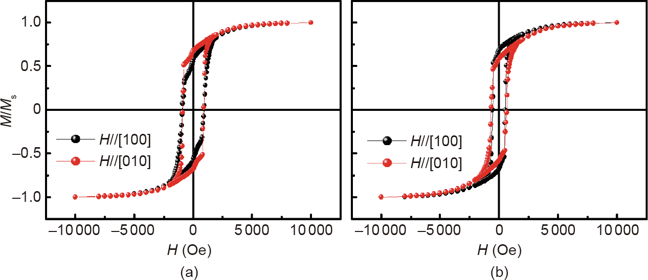
Fig. 5. Hysteresis loops of the Sm–Co films grown on (a) STO(001) and (b) LAO(001).
《4. Conclusions》
4. Conclusions
In summary, the structural properties associated with the magnetic anisotropy of amorphous Sm–Co films have been investigated. Tunable uniaxial in-plane magnetic anisotropy was produced by growing amorphous Sm–Co films onto (011)-cut single-crystal substrates in the absence of an external magnetic field. The in-plane anisotropic strain provided by the substrates strongly favors the growth of FM domains along the longer axis; hence, uniaxial in-plane anisotropy is produced. Variation of the lattice parameters of the substrates may affect the directional pair ordering, resulting in tunability of the anisotropy constant. The evaluated anisotropy constant, kA, was as high as about 3.3 × 10⁴ J·m-3 in the amorphous Sm–Co film grown on LAO(011). The present work provides a new way to obtain in-plane anisotropy in amorphous Sm–Co films. A more remarkable uniaxial anisotropy could be anticipated if a more significant anisotropy stress field was constructed by introducing a buffer or choosing a substrate with a lower in-plane structural symmetry.
《Acknowledgements》
Acknowledgements
This work was supported by the National Key Research and Development Program of China (2017YFB0702702, 2018YFA03 05704, 2016YFB700903, 2017YFA0303601, and 2017YFA020 6300), the National Natural Sciences Foundation of China (51531008, 51771223, 51590880, 11674378, 51971240, U1832 219, and 11934016), the Inner Mongolia Science and Technology Major Project of China 2016, and the Strategic Priority Research Program (B) and Key Program of the Chinese Academy of Sciences (CAS).
《Compliance with ethics guidelines》
Compliance with ethics guidelines
Wenhui Liang, Jiefu Xiong, Fengxia Hu, Jia Li, Jian Zhang, Jing Wang, Jirong Sun, and Baogen Shen declare that they have no conflict of interest or financial conflicts to disclose.


 京公网安备 11010502051620号


