

《1. Introduction》
1. Introduction
Over the past 20 years, laser machining technology has found its way into many industrial applications, such as welding [1–3], cutting [4,5], drilling [6,7], texturing [8–10], and micro-structures manufacturing [11–13]. With the development of laser machining technology and equipment, the application of this technology has gradually become popularized, from mass production to small batch customized production. It is essential to develop a laser machining technique that is more suitable for diversified products, and the advent of the galvanometer scanner greatly assists in this endeavor. A galvanometer scanner can quickly and accurately control the position of the laser spot. Compared with traditional processing methods, laser processing with a galvanometer scanner has many advantages, including high dynamic performance and processing speed, no wear on mechanical tools, contact-free processing, and exceptional flexibility without retooling [14–16].
The major challenge of three-dimensional (3D) laser machining is to continually keep the laser focus spot on a specific position in 3D space [17,18]. Noh et al. [19] proved that the microgrooves produced by an on-focus laser possess higher quality in terms of depth and uniformity compared with those produced by an off-focus laser. Cao et al. [17,20] used machine vision to compensate for a defocused laser and to continually keep the laser focused on the surface. Wang et al. [21] divided a large freeform surface into sub-areas, sub-layers, and sub-blocks to ensure that the laser was always focused. Based on the 3D surface of the workpiece, dynamic adjustment of the laser focus spot in the spatial position is the key to realizing non-planar laser machining. The 3D galvanometer scanner improves the laser beam by allowing it to change its focus position rapidly in 3D space; the 3D machining capability of the galvanometer scanner benefits from its dynamic focusing unit [22,23]. Xiao et al. [24] used a 3D galvanometer scanner to directly mark patterns on freeform curved surfaces. Diaci et al. [25] used a 3D galvanometer scanner to mark complete patterns on a curved surface and inclined surface, which could not be done using a general 2D galvanometer scanner.
Most current 3D galvanometer scanner machining systems are unable to perform 3D measurement; therefore, it is necessary to obtain the 3D information of the workpiece by means of 3D software modeling or special scanning equipment before laser machining, and the workpiece must be positioned by fixtures. However, when workpieces are produced in a small batch and are diversified, a great deal of time will be spent on preparation work, resulting in increased hardware and time costs. At the same time, multiple processes may introduce more errors. In-situ processing technology generally refers to direct in-situ measurement and processing on an object; this technology has been investigated in the fields of industry, bioengineering, and more [26–29]. When this technology is used in 3D laser machining, its main advantage lies in the integration of measurement and machining, which can simplify the traditional workflow—including individual modeling, clamping, adjustment, and alignment—and avoid the workload and errors caused by redundant processes. The galvanometer scanner can project line structured light for 3D measurement [30–32]. Diaci et al. [25] attempted to use a laser system for measurement and machining in order to complete rapid and flexible laser marking and engraving; however, they did not provide a specific implementation method for measurement or a detailed evaluation of the results.
Traditional 3D measurement using line structured light is mainly based on the direct projection of laser lines onto the surface of an object [33]. Zhou et al. [34] used line structured light to measure rails; they found that the errors in length, width, and thickness were about 0.3 mm. Liu et al. [35] measured the diameter of an axis (the diameter was about 30 mm) by means of line structured light. The diameter was obtained by fitting the measured points, and the error was found to be less than 20 μm. Li et al. [36] used line structured light to measure a cube with a height of 100 mm, and observed an error of about 1 mm. In fact, the absolute measurement accuracy is determined by factors such as the equipment, measurement distance, and algorithm. For example, a small camera field of view and a short measurement distance can result in relatively high measurement accuracy.
The current research on line structured light measurement method mainly includes measurement modeling, the optical center extraction method, and the calibration method. Measurement modeling is the basis of this technology, and is mainly based on geometric derivation. The measurement modeling using a galvanometer scanner is different from the typical method due to the use of the galvanometer scanner and different types of focusing lens. Optical center extraction is an important factor in measurement accuracy. The optical center extraction method with subpixel precision can achieve relatively high measurement accuracy, and there are mainly three types of typical subpixel methods including the Gaussian fitting method [37], gray centroid method [5], and Hessian matrix method [38]. Calibration mainly involves camera parameters calibration and light plane equation calibration. The calibration of the light plane equation is more difficult, and the problem of how to obtain high-precision control points to fit the light plane is a key issue in calibration.
In this study, a 3D in-situ laser machining system integrating laser measurement and machining was built using a 3D galvanometer scanner and an industrial camera. The main contribution of this paper is the realization of the integration of in-situ measurement and machining, including: ① the proposal of a line structured light measurement model based on a galvanometer scanner; ② the proposal of a height calibration method to ensure measurement accuracy; and ③ the development of in-situ machining software to realize time-saving and labor-saving 3D laser processing. The feasibility and practicability of this in-situ laser machining system were verified through specific cases. In comparison with the conventional line structured light measurement method, the proposed methods do not require light plane calibration, and do not require additional motion axes for 3D reconstruction. The proposed in-situ laser machining system realizes a simple operation process, which reduces labor and time costs.
《2. Methods》
2. Methods
《2.1. 3D measurement method》
2.1. 3D measurement method
Fig. 1(a) shows the 3D measurement model based on the line structured light projected by the galvanometer scanner. There are four coordinate systems in this model: the world coordinate system  , the galvanometer coordinate system
  , the camera coordinate system
  , and the image coordinate system
  . To simplify the model, the galvanometer coordinate system is coincident with the world coordinate system. In this research, a non-telecentric
  field lens was used. In Fig. 1(a), point
  is the center of the galvanometer scanner’s y -axis mirror, whose world coordinates are (0, 0, H ), where H is the height of point in the world coordinates. Points b and c are the two endpoints of the laser line projected by the galvanometer scanner. Their world coordinates can be precisely controlled by the galvanometer scanner, and are
  and
and  . To obtain the 3D coordinates of a point on the object, at least three constraints should be known. According to the typical pinhole camera model [39], Eq. (1) can be derived.

where  and
and  are the focal distance expressed in units of horizontal and vertical pixels; and
  and
and  are the principal point coordinates. Suppose that a space point d ,
  has the coordinates of d in the camera coordinate system, and
  are the coordinates in the pixel coordinate system. In order to uniquely determine the coordinate value of the point, at least one more constraint is required—that is, the light plane equation. The conventional line structured light measurement method requires calibration of the light plane to determine the light plane equation, but the light plane generated by the galvanometer scanner can be precisely controlled. The laser is focused by the field lens, which includes the non-telecentric
  field lens and the telecentric field lens. When using a non-telecentric field lens, the light plane in the world coordinate system passes through the three points
  (Fig. 1(a)); when using a telecentric field lens, the light plane is always perpendicular to the xy plane in the world coordinate system, and the world coordinates of the point
  in Fig. 1 are considered to be
  . Therefore, the three known noncollinear points (a, b, and c) in the world coordinate system can be converted to the camera coordinate system according to the camera’s external parameters, and the light plane equation in the camera coordinate system can be determined as follows:

where A, B, C, and D are the coefficients of the light plane equation. This is synchronized with Eq. (1) to obtain Eq. (3):
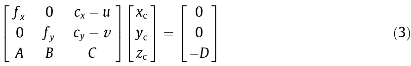
Thus, coordinates on the pixel coordinate system  can be converted to the camera coordinate system
 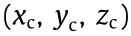 according to Eq. (3), and then to the world coordinate system
  according to Eq. (4), where R is the rotation matrix and T is the translation matrix in the camera’s external parameters.

《Fig. 1》

Fig. 1. Principle and equipment diagram of the 3D measurement subsystem. (a) Schematic diagram of the measurement method based on line structured light using the galvanometer scanner; (b) equipment diagram of the measurement and machining system.
《2.2. Height calibration method》
2.2. Height calibration method
On the basis of the methods described above, this study introduces the use of a height calibration method to ensure the measurement accuracy of the height direction. The principle of this method is to find the relationship among the actual height, the laser line offset distance, and the pixel distance; this relationship is shown in Eq. (5).

where Z is the actual height, x is the laser line offset distance, p is the pixel distance, and f represents the function of x and p . In this study, the laser line is parallel to the y -axis direction in the world coordinate system, and its offset direction is along the x -axis direction, as shown in Fig. 1(a). The three-axis motion platform can be controlled to move a certain distance in the z-axis direction and simultaneously take multiple laser line images for height calibration.
The center coordinate of the laser line in the pixel coordinate system is the optical center. The optical center with a height of 0 and a laser line offset distance of 0 is defined as the reference optical center, and the average pixel distance between any other optical center and the reference optical center is defined as P. In the plane with a height of 0, the average pixel distance between other optical centers and the reference optical center is defined as P1. When the laser line offset distance is the same and the height is different, the average pixel distance between optical centers at different heights and the optical center at a height of 0 is defined as P2. Therefore, Eq. (6) is obtained in the pixel coordinate system.

Fig. 2(a) shows the relationship between P1 and x (-30 to 30 mm, calibrated every 5 mm). Fig. 2(b) shows the relationship between P2 and Z (-15 to 15 mm, calibrated every 5 mm). It can be seen from the figures that P1 has a good linear relationship with x , and P2 has a good linear relationship with Z .
《Fig. 2》
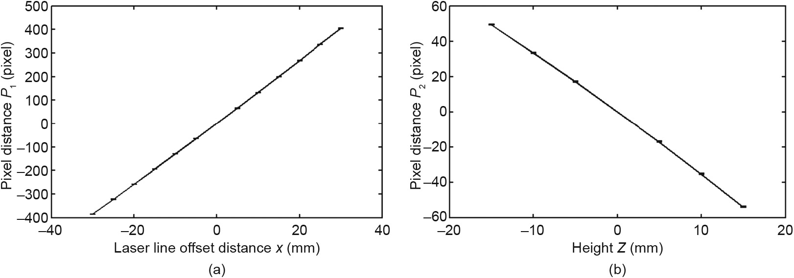
Fig. 2. (a) Relationship between the average pixel distance P1 and the laser line offset distance x in the height of 0; (b) relationship between the average pixel distance P2 and the height Z in the laser line offset distance of 0.
Fig. 3 plots the relationship among Z , P2, and x , which is almost fitted to a plane. Therefore, when calculating the actual height Z , P1 is first calculated by linear interpolation according to the value of x in Fig. 2(a); next, according to the calculated value of P, P2 can be obtained using Eq. (6). Finally, Z is obtained by interpolation using P2 and x , as shown in Fig. 3.
《Fig. 3》
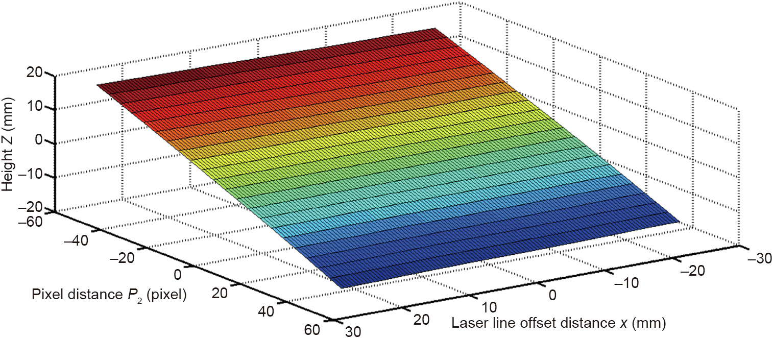
Fig. 3. 3D map of the relationship among the actual height Z , pixel distance P2 , and laser line offset distance x .
《2.3. Optical center extraction method》
2.3. Optical center extraction method
In this method, the laser line images are preprocessed by median filtering, and the gray centroid method is then used to extract the optical center. First, the point  with the highest light intensity in a column of pixels is found, and then a gray threshold
  is determined. Here, k is a scale factor, and the pixel coordinates of all points whose gray value is larger than K are set to
  ; and the corresponding gray values of these points are set to
 . Finally, the optical center U is obtained by Eq. (7):

During the extraction of the optical center by the gray centroid method, the thresholds of each column of pixels are different, so even if the gray distribution is not uniform, it will not bring great errors to the determination of the optical center position, thus improving the extraction accuracy.
《2.4. In-situ machining method》
2.4. In-situ machining method
After the extraction of the optical center, the 3D point cloud surface of the object can be obtained according to the methods described in Sections 2.1 and 2.2. The density of the point cloud is determined by the distance between the projected laser lines and the resolution of the industrial camera. The point cloud surface can reflect the actual 3D shape and pose of the object.
After obtaining the surface point cloud of the object, machining patterns or paths are projected to the corresponding position on the point cloud to generate the 3D galvanometer scanner processing instructions. In this study, the machining patterns were projected onto the 3D point cloud in the form of pixels. Each pixel in the machining pattern could find its adjacent points in the point cloud, and the average height value of these points was taken as the height value of the pixel. In order to realize in-situ machining, in-situ machining software was developed, which achieves the precise projection of patterns at any position of the workpiece by zooming, translating, and rotating the imported patterns.
《3. Experiments and evaluation》
3. Experiments and evaluation
《3.1. Equipment condition》
3.1. Equipment condition
The 3D galvanometer scanner used in this study was a SCANLAB intelliSCANse 14 equipped with a 255 mm focal length non telecentric  field lens. The industrial camera was a Vieworks VH-5MG 5-million-pixel black-and-white camera, equipped with a U-TRON FV1520 lens, and the camera was fixed on the side of the 3D galvanometer scanner. The field of view of the industrial camera was about 200 mm × 200 mm when the working distance was 350 mm. The laser source was a 1064 ns fiber laser (RFL-P30Q) with a 680 nm indicator light. The 3D galvanometer scanner was mounted on a three-axis motion platform, as shown in Fig. 1(b).
《3.2. 3D measurement accuracy evaluation》
3.2. 3D measurement accuracy evaluation
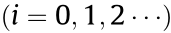
The measurement accuracy directly decides the laser focusing accuracy during in-situ processing. A standard-height step block was selected (Fig. 4(a)) with a length of 80 mm, a width of 20 mm, and four standard heights of 3, 5, 10, and 15 mm for the measurement accuracy test. The scanned laser line spacing was 0.5 mm, the scanning speed of the galvanometer scanner was 5000 mm·s-1 , and the exposure time of the industrial camera was 50 ms. 3D point clouds were generated using Method 1 (the method using the camera parameters and the light plane equation) and Method 2 (the method that includes height calibration). Fig. 4(b) shows the point cloud obtained by Method 2, which accurately reconstructs the height information of the standard-height step block. Fig. 5(a) indicates the average value of the measured height. Fig. 5(b) shows that the error of Method 1 varies with change in the y value. The error at both ends is large, and reaches a maximum at a height of 15 mm, where it exceeds 1 mm. In contrast, the error of Method 2 is stable in the height direction. It is always within the range of ±0.2 mm, and does not change significantly with change in the y value.
《Fig. 4》
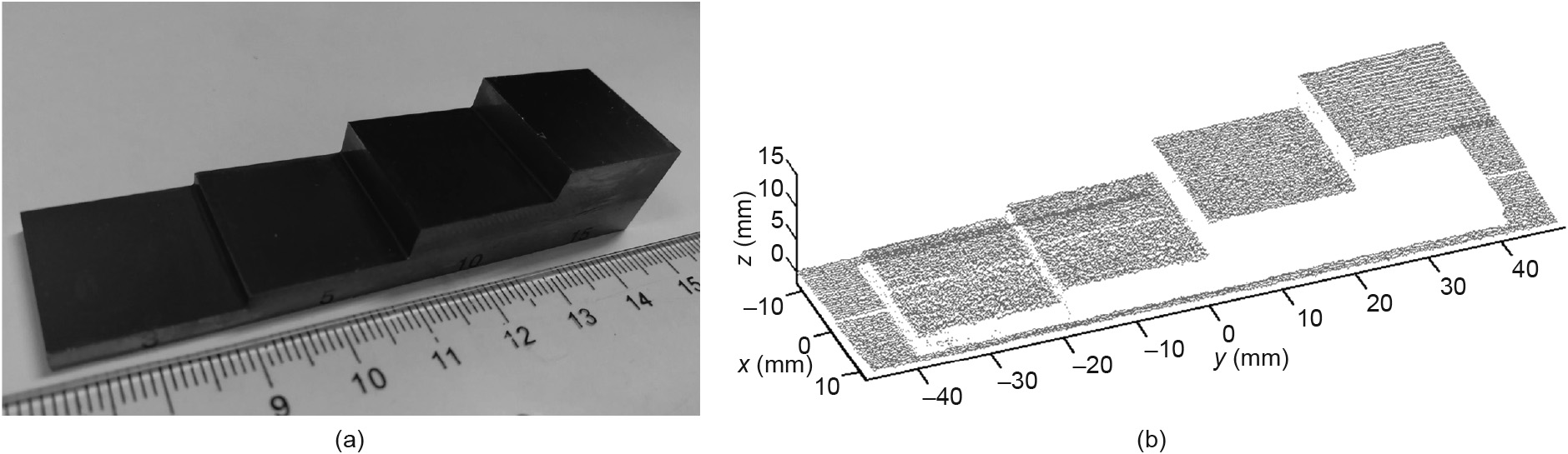
Fig. 4. (a) The standard-height step block with standard heights of 3, 5, 10, and 15 mm; (b) 3D point cloud of the standard-height step block obtained by Method 2.
《Fig. 5》
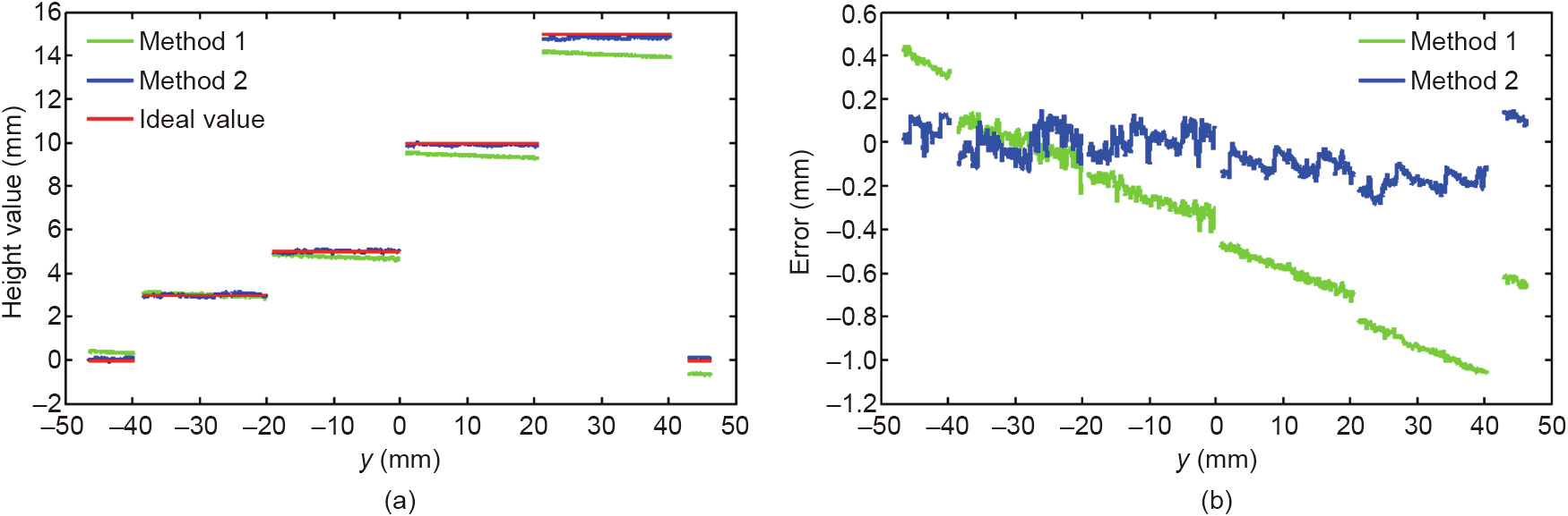
Fig. 5. (a) Average height values obtained by Method 1 and Method 2; (b) height error of Method 1 and Method 2.
The y value of the first and last points of the laser lines scanned onto the workpiece were extracted, and the length of the workpiece obtained by the scanning was calculated to be (79.900 ± 0.154) mm, which is consistent with the actual workpiece length of 80 mm.
《3.3. Implementation and examples》
3.3. Implementation and examples
3.3.1. Case 1: In-situ machining on a standard-height step block
In order to verify the function of the 3D in-situ laser machining system developed in this study, 3D measurement, pattern projection, and in-situ machining were carried out on a standard-height step block (Fig. 4(a)). This process included the following steps:
Step 1: Pre-calibration work. The Matlab camera calibration toolbox was used to perform camera calibration in order to obtain the camera’s internal and external parameters. When obtaining the external parameters, the x-axis and y-axis direction lines were projected to the chessboard to coincide the galvanometer coordinate system with the world coordinate system, as shown in Fig. 6(a). Height calibration was performed using the method described in Section 2.2.
Step 2: 3D in-situ measurement. The scanning speed of the galvanometer scanner was 5000 mm·s-1 , the exposure time of the camera was 50 ms, and the laser line was scanned every 0.5 mm to traverse the object. One of the laser line images is shown in Fig. 6(b). The optical center extracted by the gray center method is illustrated in Fig. 6(c). The 3D point cloud of the workpiece surface was generated according to the methods described in Sections 2.1 and 2.2.
《Fig. 6》
Fig. 6. Implementation process and results of Case 1. (a) The galvanometer coordinate system is coincided with the world coordinate system during camera calibration; (b) one of the laser line images during 3D measurement; (c) the optical center extracted from the laser line image, where the red line is the extracted optical center; (d) in-situ machining results on the thermal paper.
Step 3: Machining pattern projection. The generated 3D point cloud and the imported machining patterns were displayed by OpenGL. After a certain amount of zooming, translating, and rotating, the pattern was projected and displayed on the point cloud.
Step 4: 3D in-situ machining. In order to protect the standardheight step block, thermal paper was attached to it, and the laser was used to mark the patterns on the thermal paper. After in-situ machining, these patterns were consistent with the design patterns, as shown in Fig. 6(d).
In this study, the in-situ machining software (Fig. 7) was developed on a C# WinForm platform. The main functions of the software include scanning laser lines, importing the point cloud, importing machining patterns, translating and rotating the patterns, generating projection patterns, and controlling the galvanometer scanner and the three-axis motion platform.
《Fig. 7》
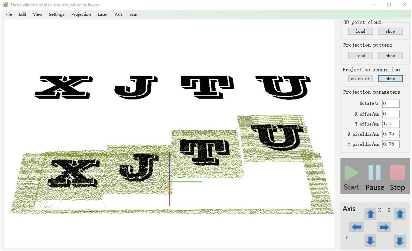
Fig. 7. The in-situ 3D machining software interface displays the 3D point cloud (brown dots) of the standard-height step block and of the machining patterns before and after projection.
3.3.2. Case 2: Local scanning and in-situ machining
When the workpiece is large, it is only necessary to scan the local part that needs to be processed in order to further reduce the unnecessary workload. In this case, a larger non-standard workpiece was selected, as shown in Fig. 8(a), the machining results were shown in Fig. 8(b). It is only necessary to ensure that the local part to be processed is within the processing range of the galvanometer scanner and the visual field of the camera. Figs. 8(c) and (d) show the measurement results of a local corner of the workpiece. Two quick response (QR) code patterns were projected on it, and the machining was directly processed after the projection. Designed patterns can be accurately marked at the corresponding position of the workpiece, which is very convenient. From the machining results, it can be seen that the processed patterns are complete and have no obvious flaws, whether on the slope or on the plane; the position and size of the in-situ machined QR code patterns are consistent with the design in the software.
《Fig. 8》
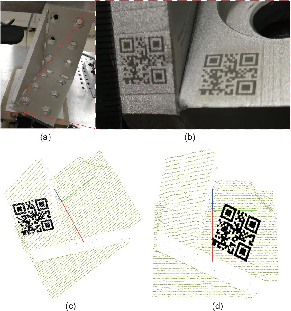
Fig. 8. Implementation process and results of Case 2. (a) A larger size non-standard workpiece on the machining platform; (b) in-situ machining results of two QR code patterns at the corner of the workpiece; (c) projection results on the slope; (d) projection results on the plane.
3.3.3. Case 3: Machining on a curved surface with different pixel distance
In order to verify the machining capacity on a curved surface, an aluminum alloy arc surface workpiece (40 mm × 40 mm × 11.5 mm) was selected as the processing object, and the pattern was projected after equal arc length transformation. The machining line spacing was artificially adjusted by the pixel distance in the in-situ machining software. The measurement and projection results are presented in Fig. 9(a). A machining line spacing of 40 and 120 μm was used, respectively. The machining results are shown in Figs. 9(b) and (c). When the machining line spacing was 40 lm, the machined pattern was filled (Fig. 9(b)); when it was changed to 120 lm, there was a gap between each machining line (Fig. 9(c)). Optical microscopy observation in the range of the red dotted box (Fig. 9) showed that the line width produced by the laser was (46.08 ± 1.22) μm, and the actual machining line spacing was (40.04 ± 0.72) and (120.11 ± 0.02) lm, respectively, which is consistent with the design values; this indicates that the system has high processing accuracy.
《Fig. 9》
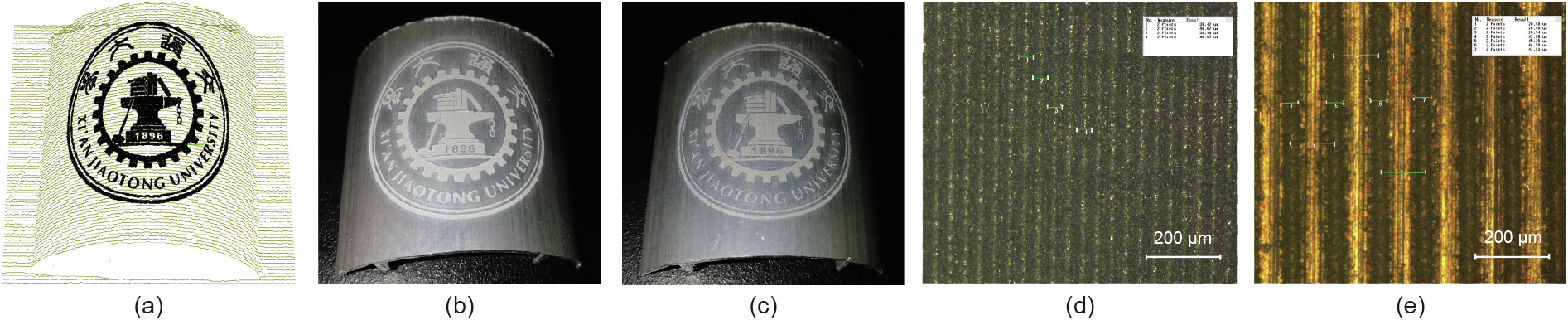
Fig. 9. Implementation process and results of Case 3. (a) Measurement and projection results of the aluminum alloy arc surface workpiece. In-situ machining results with (b) 40 lm machining line spacing and (c) 120 μm machining line spacing. Optical microscopy observation results with (d) 40 μm machining line spacing and (e) 120 μm machining line spacing.
3.3.4. Case 4: Tool in-situ measurement and micro-textures processing
Cutting tools with micro-textures can reduce friction and improve wear resistance and anti-adhesion. The proposed methods can achieve the online and in-situ measurement of a tool and fabricate micro-textures without the fixture. Fig. 10(a) shows a triangular turning tool with a particular rake angle. The scanned laser line spacing is 0.2 mm. The reconstruction results (Fig. 10(b)) clearly show the rake face and rake angle of the tool. The measured tool profile was extracted (Fig. 10(c)) and the length of the three sides and the diameter of the hole were measured using DigitalMicrograph software. When considering the tool nose radius, the actual side length  was
was  , where R is the tool nose radius, which is 0.2 mm, and Li is the side length without considering R, as shown in Fig. 10(c). The in-situ measured value considering the R and the Vernier caliper measured value are listed in Table 1. The measurement absolute error of thickness was 3 μm, and the absolute errors of the side length and hole diameter (D) were within 90 μm. The micro-textures were imported by in-situ machining software and projected on the rake face (Fig. 10(d)). The machining results of the micro-textures are shown in Fig. 10(e), and reflect an accurate processing position and uniform grooves. This method can satisfy the requirements for manufacturing different tool micro-textures by optimizing the micro-texture design and the laser processing parameters; thus, this case reflects the practical application value of the in-situ laser machining system.
《Fig. 10》
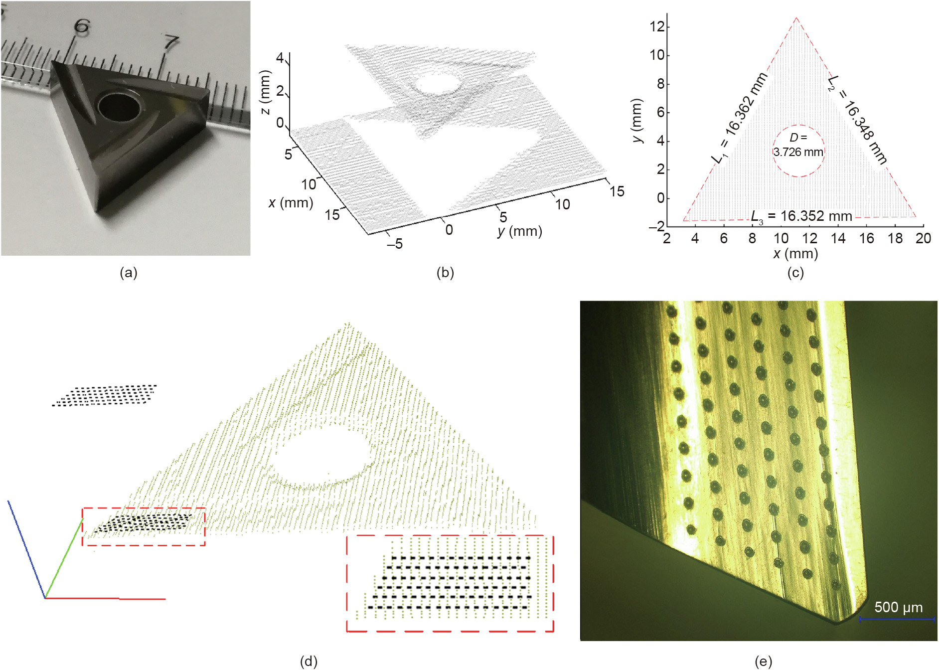
Fig. 10. Implementation process and results of Case 4. (a) Triangular turning tool with a particular rake angle; (b) reconstruction results of the tool; (c) top view of the tool profile (the dimensions in the figure are measured by DigitalMicrograph software); (d) in-situ machining software screenshot (bottom right corner is the top view of the projection of the micro-textures); (e) in-situ machining results of the micro-textures. L1, L2, L3: the side length without considering the tool nose radius.
《Table 1》
Table 1 The in-situ measured value and the Vernier caliper measured value of the tool.

D: hole diameter
《4. Discussion》
4. Discussion
Unlike the conventional line structured light measurement method, in which the laser line is directly generated by the line laser, the laser line in this study was generated by a galvanometer scanner. Because the position of the laser line in the common method cannot be accurately controlled, it is necessary to calibrate the light plane to obtain the light plane equation; a great deal of research has been conducted on this topic. For example, Liu et al. [40] used a ball target and nonlinear optimization to perform the light plane calibration, while Kiddee et al. [41] projected crossline structured light (CLSL) on the chessboard to calculate the light plane equation. These calibration methods are complicated and require accurate calibration targets. In this study, the position of the laser line can be precisely controlled by the galvanometer scanner, thus eliminating the need for light plane calibration, which greatly simplifies the process and reduces the workload. 3D reconstruction by means of the typical line structured light measurement method requires additional linear or rotary motion axes to achieve laser line scanning of the workpiece. However, the galvanometer scanner can realize self-scanning, thereby eliminating the need to add additional motion axes, and consequently saving hardware cost. Therefore, line structured light measurement method using a galvanometer scanner has technical and cost advantages.
Compared with a 2D galvanometer scanner, a 3D galvanometer scanner must acquire the 3D information of the workpiece in order to accurately focus the laser. However, most laser machining systems equipped with a 3D galvanometer scanner lack the 3D measurement capability, making it necessary to obtain the 3D information of the workpiece through other methods or equipment in advance; this is inconvenient and will increase the time cost and workload. The proposed methods add 3D measurement capability to the 3D laser machining system with just one industrial camera. The typical 3D laser machining process mainly includes 3D modeling, importing the models, and positioning the workpieces by the fixture. In comparison, the proposed methods do not require fixture positioning. In-situ measurement can obtain the 3D information of the workpiece and match the machining coordinate system, so that the laser can be focused on a certain position of the workpiece. The above method realizes a simple operation process for laser 3D machining, which greatly reduces time and labor costs.
When the workpiece size is large, the farther away a point on the workpiece surface is from the origin of the world coordinate system, the more obvious the measurement error will be. This error is due to inaccurate calibration of the camera parameters. If the measured height is inaccurate, the laser focus will be defocused during the 3D laser processing, which will directly affect the processing quality. In order to ensure measurement accuracy in the height direction, the height calibration method was proposed. This method ensures that the height error is always within a certain range, which is generally smaller than the laser Rayleigh length in the laser machining system, thereby ensuring that the laser is always focused. The error of the height calibration method mainly comes from the line structured light not being thin enough and the resolution of the camera not being high; however, the error is stable and within an acceptable range.
《5. Conclusion》
5. Conclusion
In this study, an a 3D in-situ laser machining system integrating laser measurement and machining was built by using a 3D galvanometer scanner equipped with a side-axis industrial camera. The line structured light was projected onto the workpiece surface by the galvanometer scanner, which increased the 3D measurement capability for the 3D laser machining system. A line structured light measurement model based on the galvanometer scanner was proposed. A method using camera parameters and the light plane equation was used to obtain the 3D surface information. A height calibration method was proposed to further ensure the measurement accuracy. The measurement error of these methods is stable and acceptable in the height direction. The feasibility and practicability of this in-situ laser machining system were verified using specific cases.
The advantages of the proposed methods are as follows: ① Compared with the conventional line structured light measurement method, the proposed methods do not require light plane calibration and additional motion axes to achieve 3D reconstruction, and thus provide technical and cost advantages; ② the in-situ laser machining system realizes a simple operation process by the integration of 3D in-situ measurement and laser machining, which greatly reduces labor and time costs.
For tasks that require high machining accuracy, the in-situ laser machining system can realize higher precision laser processing on a macro–micro scale by configuring a more precise coaxial vision device (such as SCANLAB’s camera adapter), which has great research value and application potential.
《Acknowledgements》
Acknowledgements
This work was supported by the National Key Research and Development Program of China (2017YFB1104602 and 2016YFB1102502) and the Program for Changjiang Scholars and Innovative Research Team in University (IRT_15R54).
《Compliance with ethics guidelines》
Compliance with ethics guidelines
Xiao Li, Bin Liu, Xuesong Mei, Wenjun Wang, Xiaodong Wang, and Xun Li declare that they have no conflict of interest or financial conflicts to disclose.


 京公网安备 11010502051620号


