
《1. A worldwide history of high-speed trains》
1. A worldwide history of high-speed trains
High-speed railway (HSR) is defined by the International Union of Railways (UIC) as new lines with design speeds above 250 km·h-1 and upgraded existing lines with speeds of up to 200 km·h-1 [1]. In China, HSR is defined as new passenger-dedicated lines designed for electric multiple unit (EMU) trains running at a speed of 250 km·h-1 or above (actual or reserved), with an initial operation speed not lower than 200 km·h-1 [2]. The worldwide development of HSRs and high-speed EMUs can be roughly divided into three stages: initial operation, line platform expansion, and rapid development.
《1.1. Initial operation (1960s to late 1970s)》
1.1. Initial operation (1960s to late 1970s)
On 1 October 1964, the world’s first HSR—the Tokaido Shinkansen (Tokyo–Shin–Osaka)—was inaugurated. The 0 Series highspeed EMUs, which consisted of six motor cars with a maximum operation speed of 210 km·h-1 , were put into service.
《1.2. Line platform expansion (early 1980s to late 20th century)》
1.2. Line platform expansion (early 1980s to late 20th century)
During this stage, HSR development expanded from Japan to Europe. France, Germany, and Italy, along with other countries, built and opened HSRs. They developed new EMU platforms with their own characteristics via different technical routes. EMU models were continually enriched and the technical performance was continually improved. The maximum operation speed was gradually raised to 300 km·h-1.
In 1983, France opened the LGV Southeast Line (Paris–Lyon), where the acronym LGV stands for ligne à grande vitesse, or high-speed line [3]. The opening of this line was a key milestone as HSR reached an operation speed of 300 km·h-1 , and marked the beginning of the expansion of HSR development from Japan to Europe. Later, France opened the LGV Atlantic Line (Paris–Le Mans/Tours) and other lines, using TGVs (trains à grande vitesse, or high-speed trains) with a maximum operation speed of 300 km·h-1 , developed by Alstom. In 1991, Germany opened the Hannover–Fulda–Wurzburg and Mannheim–Stuttgart HSRs with a maximum operation speed of 280 km·h-1 , using the ICE1, ICE2, and other models of power-concentrated high-speed EMUs developed by Siemens. In 1992, Italy opened the Rome– Florence HSR section by section with a maximum operation speed of 250 km·h-1 , using the ETR450, ETR460, and other models of power-distributed tilting trains, which were independently developed by Fabbrica Italiana Automobili di Torino (FIAT; now controlled by Alstom). In 1992, Spain opened the Madrid–Seville HSR using S100 concentrated-powered EMUs with a maximum operation speed of 300 km·h-1 . The technology introduced by Alstom was applied to these EMUs. In Japan, the Shinkansen technological system progressed further. Following the technical route of power distribution, various models of high-speed trains, such as the 100, 200, 300, 400, 500, and 700 Series and the E1, E2, and E3 Series, were developed and put into service. Among them, the 500 Series EMUs reached a maximum speed of 300 km·h-1 in 1997.
It can be concluded that the world’s high-speed EMU technology was relatively mature in this stage. Different technical routes for power concentration and power distribution were established, and tilting and non-tilting trains emerged. Train models were continually enriched and their speed continued to rise. Major manufacturers such as Siemens and Alstom began to establish themselves. HSRs had a huge effect on these countries as they delivered new vitality and vigor to economic and social development.
《1.3. Rapid development (since the 21st century)》
1.3. Rapid development (since the 21st century)
Since the beginning of the 21st century, the world has witnessed the rapid development of HSRs. Countries such as the United States, Russia, Korea, Poland, and China began to develop HSRs. In particular, the rapid rise of China’s HSRs greatly facilitated the development of HSR around the world. In the first decade of the 21st century, HSRs with a total length of nearly 15 000 km were built across the world—a length over three times greater than that of the HSRs built 30 years ago.
With the development of HSR lines, the performance of highspeed EMUs was continually optimized and the development of the platform-based EMU gained momentum. France developed and operated the TGV Paris–Ostfrankreich–Süddeutschland (POS) and TGV Réseau Duplex EMUs, as well as the TGV Duplex Dasye, TGV Duplex RGV2N2, and TGV Océane double-deck EMUs, with a maximum operation speed of 320 km·h-1 . Alstom changed its previous route of power concentration and successfully developed distributed-powered automotrice à grande vitesse (AGV) EMUs, which were put into the operation by Nuovo Trasporto Viaggiatori (NTV), an Italian private railway company. Germany also changed its previous technical route of power concentration, and developed and operated power-distributed ICE3 and new ICE3 EMUs with a maximum operation speed of 300 km·h-1 . In addition, Germany developed the ICE4 EMUs—the predecessor of EMUs with flexible formation. Several technical innovations were applied to this EMU model, which can run at a speed of up to 230 or 250 km·h-1 depends on 7-car or 12-car train configuration. Moreover, ICE T tilting EMUs (with a maximum speed of 230 km·h-1 ) and ICE TD tilting diesel multiple units (DMUs), with a maximum speed of 200 km·h-1 , were developed for existing lines with many curves. Italy operated the Red Arrow 1000 EMUs with a design speed of 400 km·h-1 and a planned operation speed of 360 km·h-1 . These EMUs are non-articulated and power distributed, and consist of eight cars and a single deck. Currently, their maximum operation speed is 300 km·h-1 . Japan operated the E5 and E6 Series EMUs on the Tohoku Shinkansen. The H5 Series EMUs served the Tohoku Shinkansen with a maximum operation speed of up to 320 km·h-1 and were adapted to operation in the cold and snowy climate of Hokkaido. During this stage, EMU manufacturers began to expand their overseas markets. For example, Siemens’ Velaro E Series EMU technology was introduced to Spain, Russia, and other countries, and Alstom’s TGV technology was introduced to Korea and the United States.
In general, over the three stages, EMUs were developed into modular series products around the world [4]. Germany’s ICE series EMUs include multiple models such as ICE1, ICE2, ICE3, ICE3M, and ICE4. France’s TGV high-speed trains experienced the development of four generations: the first generation of the TGV-PSE and post-high-speed trains; the second generation of the TGV-A, AVE, TGV-R, TGV-TMST (Euro-Star), and TGV-PBKA; the third generation of the TGV-2N, and so forth; and the fourth; generation of the AGV high-speed trains. Japan’s high-speed EMU trains include two series. The first comprises high-speed trains that are numbered by hundreds: the 0, 100, 200, 300, 400, 500, 700, and 800 Series and the N700 Series. The other comprises the E Series high-speed trains, including E1, E2, E3, E4, and E5. The platform-based and modular approach makes it easier to meet the needs of the market, including utilization modes, operation environments, and so forth, via various train formations and modular design. It also facilitates the upgrading of trains and shortens the appraisal time and access process.
《1.4. The development of China’s HSRs》
1.4. The development of China’s HSRs
The development of China’s high-speed EMU technology passed through three stages: independent exploration; introduction, assimilation, and re-innovation; and overall independent innovation. At present, China’s high-speed EMU products cover speeds of 250, 300, 350 km·h-1 , and above, and can be adapted to different lines, different environmental conditions, and different transportation requirements.
The independent exploration stage began at the end of the 20th century. In 1997, China launched its first large-scale speed-up campaign. In 1999, construction commenced on the Qinhuangdao– Shenyang Passenger-Dedicated Line with a design speed of 250 km·h-1 . During this stage, China independently developed the China Star and Pioneer EMUs. The introduction, assimilation, and re-innovation stage started in 2003. In 2004, the Chinese Government issued the Medium- and Long-term Railway Network Planning directive and proposed to plan and build an HSR network composed of four south–north lines and four west–east lines. The Beijing–Tianjin Line, Zhengzhou–Xi’an HSR Line, Shanghai–Nanjing Line, Beijing–Shanghai Line, and Harbin–Dalian Line were put into operation [5]. During this stage, China introduced four prototype EMUs from Bombardier, Kawasaki, Siemens, and Alstom, and built four China railway high-speed (CRH) EMU platforms: CRH1, CRH2, CRH3, and CRH5. Among these, the design speeds of CRH2C, CRH3C, and the 380 Series EMUs are 300 km·h-1 or above. The CRH2C formation is 6M2T (M: motor car; T: trailer car) and the CRH3C formation is 4M4T. Both EMUs were put into operation in 2008. The CRH380A formation is 6M2T and the CRH380AL formation is 14M2T. Both CRH380B and CRH380D are 8-car (4M4T) formations. CRH380BG was specially designed based on CRH380B for operation in cold and snowy areas. Both of the CRH380BL and CRH380CL EMUs are long trains with an 8M8T formation, and are specially designed for long major trunk lines such as the Beijing–Shanghai Line and the Beijing–Guangzhou Line. The maximum operation speed of the CRH Series is 300 km·h-1 .
China’s independent innovation stage started in 2013. During this stage, the China Railway Corporation organized the development of China standard EMUs with independent intellectual property rights. The Fuxing Series EMUs have two platforms, CR400AF and CR400BF, and are 8-car (4M4T) EMUs with a design speed of 350 km·h-1 and a current actual operation speed of 350 km·h-1 . In 2018, CR400AF-A, CR400BF-A, CR400AF-B, and CR400BF-B EMUs were launched to meet the transportation requirements of long major trunk lines such as the Beijing–Shanghai Line. Here, “-A” and “-B” stand for the 8M8T formation and the 8M9T formation, respectively.
As of October 2019, China has already owned 3480 EMUs (converted into 8-car formation) and more than ten billion trips had been made by these EMUs. At present, China has become a country that boasts HSRs with the highest operation speed, the largest scale, and the most diversified operation scenarios.
《2. Improved comprehensive technical performance》
2. Improved comprehensive technical performance
The HSR is a complex system. As mobile equipment, high-speed EMUs have a coupling relationship with fixed infrastructure including catenaries, tracks, and the surrounding air. In a sense, this relationship is even more complicated than those of other transportation systems such as road vehicles, aircraft, or ships. In order to further improve the comprehensive performance of high-speed EMUs, it is necessary to properly deal with these coupling relationships. In addition, it is necessary to address the traction and brake-control technology, improve the traction and braking performance, and further improve the running safety monitoring level.
《2.1. Improving the wheel–rail relationship to ensure good dynamic performance》
2.1. Improving the wheel–rail relationship to ensure good dynamic performance
Among various coupling relationships, the wheel–rail relationship is the most basic and decisive constraint relationship. Highspeed EMUs rely on wheel–rail adhesion to generate traction force and braking force, and rely on the wheel–rail contact force to secure vertical positioning (support) and horizontal positioning (lateral guidance). Restricted by the wheel–rail relationship, the bogies of high-speed EMUs undergo inherent hunting instability when the speed reaches a certain value. The theoretical maximum ultimate speed of EMUs is largely limited by the critical speed of hunting. Therefore, high-speed EMUs at the maximum operation speed not only need a sufficient safety margin, but also require an adequate critical speed margin. According to Ref. [6], during testing and certification, high-speed trains must pass a dynamic performance test at a speed that is 10% higher than the maximum operation speed, so as to verify their dynamic performance including the running stability, lateral stability, running quality, and running smoothness.
Many factors affect the stability of EMU operation. In terms of the EMUs themselves, the bogie structure and suspension are the main factors. Studies are being carried out in various countries all over the world on improving train dynamic performance; these studies are led by the development of bogies and are based on the study of the wheel–rail relationship.
CR400AF/BF Fuxing EMUs adopt a new bogie construction, suspension connection, and traction way to achieve an overall lightweight design, reduce the bogie unsuspended mass, and optimize the suspension parameters between the bogie and the car body. They are characterized by safety and comfort, good adaptability to lines, high reliability, and easy maintenance. The following main factors were considered in the design of the bogies:
(1) Adaptability to lines: As HSR lines in China are long with large span-of-operation sections, bogies must be fully adapted to different natural environment conditions, line conditions, and operation conditions.
(2) Operation safety: The bogie technology involves wheel–rail dynamics, static strength, and fatigue strength design theory. Matching of the wheel–rail relationship with the bogie structure and suspension should be considered to ensure a sufficient margin for the safety, lateral stability, and structural strength.
(3) Comfort: Bogies should be designed in a way that ensures excellent riding comfort. In order to keep trains running smoothly at a high speed, two-stage suspension was adopted for the bogie structure in order to isolate the unspring vibration and suppress the vehicle vibration [7]. The vibration acceleration in cars should be less than 2.5 m·s-2 . Based on simulation calculations, laboratory bench tests, and line tests, a dynamic performance analysis was performed, the suspension system scheme was determined, and the suspension parameters were optimized.
(4) Reliability: Bolster-less bogies equipped with high-flexibility air springs and high-damping anti-yaw damper have replaced the outdated passenger car bogies—which have a complicated structure that involves many parts and components, with bolsters or even swing-bolsters and friction-type side bearings. This change significantly simplified the structure and improved the operation reliability.
(5) Light weight: By optimizing the structure and using new high-strength lightweight materials, the frame mass and unspring mass were reduced. Through finite-element analysis, an evaluation and a modal calculation were performed on the static strength and fatigue strength of the bogie frame, the bogie structure was optimized, and lightweight high-strength materials were appropriately used for some parts and components.
(6) Easy maintenance: A modular design was adopted to facilitate the disassembly and maintenance of the main parts and components of the bogies. Based on the wheel–rail contact relationship, the wheelset positioning mode, and the parameters of the bogies, the wheel profile was optimized and a thin-flange re-profiling technology was used to prolong the wheel re-profiling cycle and the service life of the wheels.
(7) Running safety monitoring: Bogie lateral instability monitoring, axle-locking monitoring, and wheelset bearing temperature monitoring devices have been equipped. In addition, safety thresholds are set for warnings or alarms to ensure the running safety of the bogie.
The Fuxing EMUs have two platforms: CR400AF and CR400BF. The bogies of each platform are classified as motor bogies or trailer bogies. Both types of bogies have a two-axle bolster-less lightweight structure. The trailer bogie is composed of the frame, wheelset, journal box guidance, primary suspension, secondary suspension, brake rigging, and bogie auxiliary devices. The motor bogie is additionally equipped with a gear box and motor drive device. The motor bogie and trailer bogie of the CR400AF EMU are respectively shown in Figs. 1 and 2. The design index of the bogie bearing capacity is 17 t of axle load. The results of laboratory rolling and vibrating testing proved that the critical speed of the EMU bogies exceeds 550 km·h-1 . The results of line testing indicate that the running stability of Fuxing EMUs is clearly better than that of CRH EMUs. When a Fuxing EMU train runs on the Beijing– Shanghai Line at 350 km·h-1 , the average lateral stability value of the cars decreases by about 21% and the average vertical stability value of the cars decreases by 11%.
《Fig. 1》

Fig. 1. Motor bogie of the CR400AF EMU.
《Fig. 2》

Fig. 2. Trailer bogie of the CR400AF EMU.
《2.2. Resolving the pantograph–catenary relationship to ensure good current collection performance under high-speed operation》
2.2. Resolving the pantograph–catenary relationship to ensure good current collection performance under high-speed operation
The pantograph–catenary relationship is another important coupling relationship of the HSR system. Pantographs moving at a high speed on EMUs must be in close contact with the fixed catenary wire to achieve good current collection. Friction occurs between the pantograph and catenary, among which the electric power is transmitted.
For HSRs of above 300 km·h-1 , the pantograph–catenary current-collection performance has a direct influence on the operation speed and safety of trains. Indexes such as the pantograph–catenary contact force, the arc, and the vertical acceleration of the pantograph pan are very important. As the EMU speed increases, the vibration amplitude of the pantograph head and catenary wire also increases, resulting in sharp fluctuation of the pantograph– catenary contact force and impairment of the current-collection quality. If the pantograph–catenary contact force drops to zero due to severe vibration of the pantograph and catenary, the pantograph and catenary will separate from each other, and an electric arc will be generated. This electric arc will burn the pantograph and catenary wire, and may even cause interruption of power transmission and affect the safety of the train operation. If the contact force is too large, the lift of the catenary wire will exceed the allowable value, causing pantograph–catenary wear loss and even a pantograph–catenary accident.
For CR400AF/BF EMUs, the following technical measures are necessary in order to optimize the pantograph–catenary relationship:
(1) Rational matching of pantograph–catenary parameters: Perform calculations and simulation analysis on the dynamic current-collection performance of the pantograph–catenary system during high-speed operation, and select rationally matched pantograph–catenary parameters to achieve good current-collection performance.
(2) Use of active-control pantograph: Carry out active control over the pantograph and improve the following performance of the pantograph in order to keep the pantograph–catenary contact force within a reasonable range, reduce the wear between the catenary wire and pantograph pan, prolong the service life, and strengthen the EMU’s adaptability to operation on different lines. The geometry of the pantograph of high-speed EMUs must be compatible with the catenary, so as to achieve good contact between the pantograph and catenary wire. Friction and wear between the pantograph and catenary are inevitable, but excessive wear of the catenary wire and pantograph pan should be avoided.
(3) Optimized dynamic performance: Improve the pantograph–catenary relationship and current-collection quality by improving the dynamic and aerodynamic performances of the pantograph, as well as the pantograph–catenary dynamic performance. Reduce the occurrence of electric arcs and contact current-collection loss by stabilizing the current-collection technology, so as to reduce excessive pressure on the catenary wire and reduce the wear on the pantograph–catenary contact area.
(4) Strength analysis: Carry out a strength calculation for the whole pantograph and check the strength of specific pantograph parts and components to ensure a large safety margin for the static strength of the whole pantograph and of each component.
(5) Rapid pantograph-dropping protection: Use an emergency pantograph-lowering system that is not electrically controlled to ensure that the pantograph head will drop by more than 200 mm within 1 s in the case of a pantograph–catenary accident, and thus ensure the safety of the train and the power-supply system.
The HSR pantograph–catenary relationship is one of the main directions of HSR technological research in all countries with HSRs. European railway companies are studying the application of multivoltage-compatible pantograph technology in order to reduce the number of pantographs. Fewer pantographs will reduce the train weight, air drag, contact noise, and costs of operation and maintenance. Only one pantograph per train is ideal, in this case, the current capacity must be considered in the design of the pantograph and in the installation of a spare pantograph. A single multivoltage-compatible pantograph is required for a multi-system EMU.
《2.3. Improving the traction power performance to optimize motor control and adhesion control strategies》
2.3. Improving the traction power performance to optimize motor control and adhesion control strategies
The development of alternating current (AC) drive technology depends on the improvement of power semiconductor and converter technology, as well as on the improvement of control methods and devices. The latter could allow the whole converter–motor system to have excellent control performance to meet the requirements of different applications. Performance requirements include: smooth startup, suppression of wheel slip and slide, regenerative braking, and a broad range of speed regulation.
In order to meet the overall EMU technical requirements [8], the traction capacity of CR400AF/BF EMUs must meet the following requirements in seating capacity load on straights: ① The average acceleration must not be less than 0.4 m·s-2 when the operation speed is 0–200 km·h-1 ; ② the residual acceleration must not be less than 0.05 m·s-2 when the operation speed is 350 km·h-1.
Characteristic traction/regenerative braking curves for the CR400AF and CR400BF EMUs are shown in Figs. 3 and 4.
《Fig. 3》

Fig. 3. Characteristic traction/regenerative braking curve of the CR400AF EMU.
《Fig. 4》
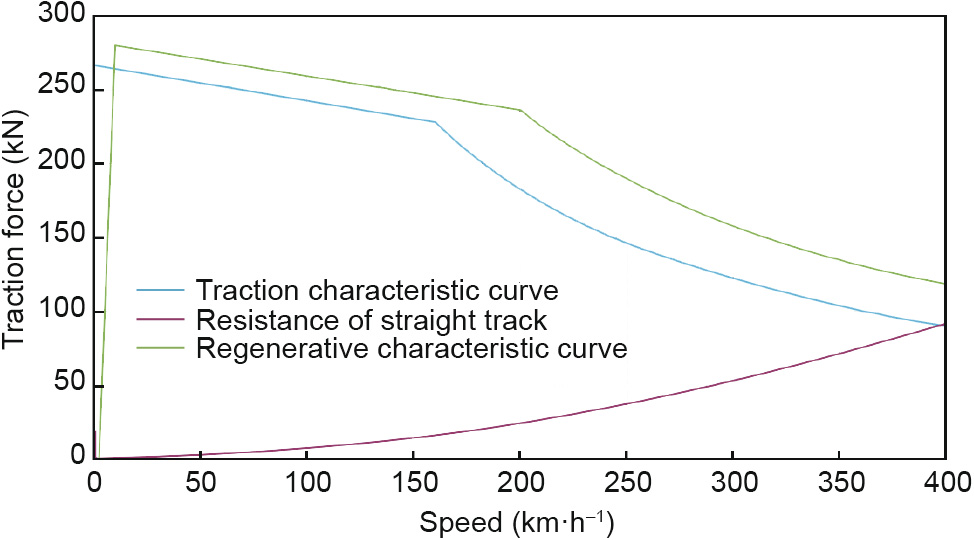
Fig. 4. Characteristic traction/regenerative braking curve of the CR400BF EMU.
Traction system design, equipment development, and optimization of matching parameters for the CR400AF/BF EMUs were carried out for aspects such as system efficiency, voltage and current, electrical parameters, mechanical interface, and weight. Through simulation analyses and testing, excellent performance of the traction system was finally achieved.
(1) Given the lightweight design of the traction system, the power-to-weight ratio of the complete vehicle is about 20.7 kW·t-1 and the efficiency of the traction system is above 0.85. The power density of the main components of the traction system is significantly higher than that of the CRH EMUs at the same speed class: ① The power density of the traction/auxiliary converter is up to 0.82 kVA·kg-1 , while that of the CRH380A is 0.43 kVA·kg-1 and that of the CRH380B is 0.63 kVA·kg-1 . ② The power density of the traction transformer is 0.99 kVA·kg-1 , which is higher than the value of 0.91 kVA·kg-1 for the CRH3C. ③ The power density of the traction motor is 0.909 kVA·kg-1 , which is higher than the value of 0.78 kVA·kg-1 for the CRH380B.
(2) For the cooling capacity design of the EMU traction cooling system, the operation environment of China’s HSRs was fully considered and a 15% margin was set for full-load operation. Even during China’s unique spring season, when catkins fly everywhere, the traction system can still work reliably. Therefore the cleaning cycles of the filter of the traction converter box reduced and the converter over temperature fault issues also reduced. The availability of the EMUs has been improved.
(3) Regarding the control of the traction system, the control strategy for the traction drive system of high-speed EMUs has been optimized to realize high-performance control and perfect fault diagnosis of equipment such as traction transformers, traction converters, and traction motors, so as to meet the requirements of high-speed EMU startup and continuous operation at a high speed. The traction-control system exhibits the technical characteristics of high efficiency, energy conservation, safety, and reliability. The two steps required to achieve this result are described below:
Step 1: Implement a strategy of two-phase duplex four-quadrant rectifier control to improve the system stability and dynamic response speed. Use phase-shifting technology to effectively control the harmonics and ensure the recovery quality of regenerated energy. Implement the strategy of hybrid pulse-width modulation (PWM) for the traction inverter based on the current harmonic optimization in order to effectively improve the grid-side harmonic distribution and mitigate the power supply grid pollution.
Step 2: Implement the strategy of high-performance traction motor control to effectively suppress the torque ripple of the traction motor in order to enable the high-power traction inverter to achieve good output waveform and control performance in the full speed range [9]. Fig. 5 shows the PWM waveforms at each switching time of the carrier ratio.
《Fig. 5》

Fig. 5. PWM waveforms at each switching time of the carrier ratio. (a) 11 pulse to nine pulse switching; (b) nine pulse to seven pulse switching; (c) seven pulse to five pulse switching; (d) five pulse to three pulse switching.
(4) Develop and use new semiconductor switching components. The 6500V/750A insulated gate bipolar transistor (IGBT) with high turnoff voltage, high conducting current, and high switching frequency was used on the CR400 EMU; it effectively reduces switching loss, improves the working stability of the traction converter system, and ensures the continuous high-speed operation capability of the EMU.
(5) Design an emergency traction function. Even if the EMU network communication system is paralyzed, the traction force can still be exerted according to commands via wired signals, so that the train can still be operated downgrade and avoid dangerous sections.
(6) Realize neutral-section passing control without powersupply interruption and self-power generation during no-power returning operations/rescue. Loads for auxiliary systems, such as air conditioners and air compressors, can still work normally during neutral-section passing and no-power returning operations. Thus, the availability, comfortability and service quality of the EMUs are improved.
The traction system and its control technology are always decisive factors when updating EMU products. The control (speed-regulation) technology of the AC asynchronous motor is more complicated than that of the direct current (DC) series excited motor. Slip characteristic control was used for earlier AC-driven high-speed EMUs, such as Japan’s 300 Series. Since the 1980s, vector transformation control has been widely used for three-phase AC-driven locomotives and for EMUs in other countries. Typical representatives are the ICE Series high-speed EMUs (including ICE1–ICE3) of Siemens (Germany). In 1985, Germany and Japan invented an advanced control technology, namely, direct torque control (DTC), which achieved a drive performance comparable to vector control but had a simpler structure. Today, both the technologies mentioned above are widely used to control the traction motors of high-speed EMUs in China and other countries. In China, DTC is used for the CR400AF EMUs and vector control is used for the CR400BF EMUs.
《2.4. Adopting a combination of multiple braking modes and optimizing the brake control and anti-slide strategy》
2.4. Adopting a combination of multiple braking modes and optimizing the brake control and anti-slide strategy
The following key technologies are used for the brake system control of the CR400AF/BF Fuxing EMUs:
(1) The system strengthens the performance and reliability of the microcomputer-based straight electro-pneumatic brake system, makes full use of regenerative braking, and can conveniently adjust the braking force. The composite braking mode is adopted. In general, priority is given to the electric brake in the service braking condition. In this way, the wear between the brake lining and the brake disc is reduced, and energy conservation and environmental friendliness are ensured. For emergency braking, an electropneumatic combined emergency brake is applied. The pure pneumatic emergency brake is still used as the ultimate safeguard.
(2) All the management, calculations, and distribution of the train braking force are performed by the brake system, and unified deceleration curve control is adopted to achieve satisfactory brakecontrol performance.
(3) With an increase of speed, the wheel–rail adhesion coefficient becomes lower and lower [10], and the possibility of sliding during train braking becomes correspondingly greater. To this end, the strategy of braking force distribution and brake-control anti-sliding during braking at a high speed has been optimized.
(4) The kinetic energy of the train braking is in direct proportion to the square of the speed. When a high-speed train is braked, a huge thermal load will be generated. A brake disc that can absorb the thermal load and a brake lining with good thermal cracking resistance and thermal fading resistance have been developed.
(5) The system diagnosis and fault-oriented safety control have been improved. EMU braking safety mainly involves the braking capability, reliability, and fault-oriented safety design of the brake system.
(6) For reliability and maintainability, the system is endowed with the technical characteristics of modularization and standardization.
The brake system of the CR400AF/BF Fuxing EMUs is composed of the brake-control system, air-supply system, and foundation brake rigging. The system composition is shown in Fig. 6.
《Fig. 6》

Fig. 6. Composition of the CR400AF/BF Fuxing EMU brake system. BP: Braking pipe.
The CR400AF/BF brake-control system receives braking commands from the driver, the Train Control and Monitoring System (TCMS) or the train’s automatic-speed-control system (ATP), manages and distributes the pneumatic and regenerative electric braking force, and either generates braking pressure to drive the foundation brake rigging to act and generate braking force or sends a regenerative braking force command to make the traction system exert an electric braking force. The air-source system mainly consists of the main air compressor unit, drying device, auxiliary air compressor, air cylinder, and main air pipe passing through the whole train. The foundation brake rigging consists of the brake disc, braking clamp, and brake lining. It is installed on the bogie. A pneumatic disc type of foundation brake rigging is used for both the motor cars and trailer cars. The trailer cars use an axlemounted brake disc and the motor cars use a wheel-mounted brake disc.
Electro-pneumatic composite brakes are widely used for highspeed EMUs in various countries. However, pneumatic braking is still the most basic braking mode for high-speed EMUs. For example, in France, except for the first-generation TGV EMUs, which used automatic electro-pneumatic brakes, all other TGV EMUs use the updated microcomputer-controlled electrically commanded straight electro-pneumatic brakes. As for foundation brake rigging, the third- and fourth-generation TGV EMUs mostly use disc brakes. The electric brakes used for high-speed EMUs in various countries mainly include resistive brakes and regenerative brakes. Resistive brakes enable EMUs to generate braking force in case of a power grid failure, and are safe. However, if they are used, it is impossible to conserve energy. Regenerative brakes have advantages and disadvantages that are opposite to those of resistive brakes, as they can improve the power factor of the catenary power supply system and thus save energy. In Japan, EMUs use regenerative brakes—except for the early high-speed EMUs, which used resistive brakes. In Germany, all of the ICE Series EMUs have used regenerative brakes from the beginning.
《2.5. Solving the problems of aerodynamic drag reduction and a lightweight carbody》
2.5. Solving the problems of aerodynamic drag reduction and a lightweight carbody
Aerodynamic drag is an important component of vehicle operation resistance. Therefore, reducing aerodynamic drag is important for reducing the resistance of high-speed trains. For the CR400AF/ BF Fuxing EMUs, many studies and tests have been conducted on the head shape design, carbody cross-section and profile, carbody weight, bogie area, and pantograph area, which affect the train operation resistance and energy consumption. Measures to reduce the operation resistance of the CR400BF Fuxing EMU are shown in Fig. 7.
《Fig. 7》

Fig. 7. Reduction of the CR400BF Fuxing EMU operation resistance.
(1) Optimization of the head shape: A streamlined head was designed by adopting fluid–solid coupling technology and analyzing the coupling relationship of performance indexes such as resistance, lift, operation safety and stability, aerodynamic noise and other performance indicators. The comprehensive aerodynamic performance was improved by increasing the slenderness ratio and adopt other measures.
(2) Surface smoothing: Smoothing was performed for the roof air conditioning units; the windshield connection between cars was optimized; and the aerodynamic shape of the bogie area was optimized and improved.
(3) Flow control: By using flow-control technologies such as spoilers and grooves, the surface flow field of the EMUs was corrected and optimized to reduce aerodynamic drag, mitigate the impact of the pantograph flow field on the pantograph dynamic performance, and reduce air drag.
(4) Equal strength concept design: In order to prevent the light weight of the carbody from affecting the vehicle performance (e.g., in terms of structural strength, rigidity, and air-tightness strength), an optimization design was conducted for the carbody structure based on the design concept of equal strength. The load rate of each component was balanced based on simulation calculations.
(5) Simulation analysis and model testing: To establish typical high-speed EMU models and environmental models of tracks, tunnels, and so forth, a simulation analysis was performed on the distribution laws of the air flow field of the EMUs under conditions such as operation on an open line, meeting on an open line, and passing through a tunnel for different speed classes. The aerodynamics and aerodynamic noise performance of EMUs with different shapes were systematically studied by simulation analysis, wind tunnel testing, and dynamic model testing.
(6) Lightweight carbody design: The carbody weight was reduced, mainly by innovating in materials and optimizing the structure. Under the precondition of ensuring the strength and rigidity of the carbody, the production process of the Fuxing EMUs was optimized and improved. Ultrathin long hollow aluminum alloy extruded profiles were used for the entirety of each car. The profiles were welded step by step to form a thin-wall drum that served as the bearing structure. In this way, the residual stress and welding deformation were effectively reduced and the welding efficiency was improved. The structures of the train head and the carbody are shown in Figs. 8 and 9.
《Fig. 8》

Fig. 8. Head car structure of the Fuxing EMU.
《Fig. 9》
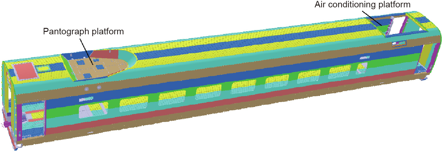
Fig. 9. Structure of the middle car of the Fuxing EMU with the pantograph.
Through aerodynamic drag reduction and a lightweight carbody design, the operation resistance of CR400 EMUs has been significantly reduced. The total resistance of the CR400AF at 350 km·h-1 is 12.3% lower than that of the CRH380A, and the total resistance of the CR400BF is 7.5% lower than that of the CRH380B.
Other countries have focused their efforts on strengthening the train aerodynamic design and on research for HSRs. In Japan, during the head shape design for high-speed EMUs, in-depth research was conducted on the air drag, aerodynamic noise, tunnel micro-pressure wave, and so forth. The heads of the highspeed EMUs from the 0 Series to the 500 Series were gradually lengthened. In order to mitigate the micro-pressure wave, unique head car shapes were developed for the 700 Series and E4 Series. Japan has adopted a bionic shape design concept in its aerodynamic shape design for high-speed trains since the development of the N700 Series. N700A and N700S have a ‘‘double-wing dorsal-fin streamlined head” optimized by three-dimensional (3D) simulation, which can reduce the aerodynamic noise when the train enters a tunnel [11]. The smoothed carbody and optimized shape can reduce the operation resistance. This experience has become mature through the design of the N700, E5, E6, and E7 Series.
In order to improve the operation speed of trains, all countries with HSRs attach great importance to a lightweight design for high-speed trains. A double-shell structure and a modular and integrated structural design have been adopted, and new structural materials have been used to reduce the carbody weight. At present, the main carbody structure is a double-shell large hollow extruded aluminum structure, which has been widely used for Japan’s main models such as the 700, N700, and E6 Series. In Germany, the double-shell structure is also used for new ICE trains. In Italy, many light alloy materials are used for the car shell and interior of the ETR 1000 high-speed trains. In this way, the carbody weight can be reduced and resources can be reclaimed and reused.
《2.6. Adopting comprehensive monitoring and diagnosis to ensure safe EMU operation》
2.6. Adopting comprehensive monitoring and diagnosis to ensure safe EMU operation
As the operation speed of EMUs continues to increase, severe problems arise in the system equipment status and operation safety of EMUs. In case of hot axle failure, sliding failure of locking axle, lateral instability, and other faults of EMUs, there are high safety risks.
In order to monitor the equipment status and operation safety of EMUs, various sensors are installed on EMUs. The sensors connect the control equipment of most systems, and the status is collected by the control equipment. The train communication network (TCN) system shares the information of each system and thus implements the control monitoring and diagnosis of the entire EMU. Equipment connected to the TCN includes traction equipment, braking and anti-slide devices, train auxiliary equipment (e.g., air conditioning, heating, ventilation, and lighting), communication and signaling equipment, a bogie-instability detection device, a journal box temperature-detection device, a fire and smoke alarm device, a passenger information system, and a diagnosis system.
More than 2500 monitoring points are set on each CR400AF/BF EMU train. The sensors at these points collect more than 1500 items of vehicle status information, diagnose the operation faults of the EMU in real time, and carry out automatic warnings or alarms in case of abnormality. For example, EMUs are equipped with devices that monitor the wheelset and gearbox bearing temperature and the bogie lateral stability. When there is a warning or an alarm, these devices promptly provide emergency treatment and maintenance suggestions, and automatically control the speed limit or train stopping according to the safety strategy, so as to ensure the operation safety of the EMU.
In all countries with a HSR, various sensors are installed at key parts of high-speed EMUs to monitor all the parameters in real time and prevent the occurrence of accidents. For example, France’s AGV EMUs are equipped with speed-monitoring devices, tripod cardan shaft imbalance and fracture-monitoring devices, and car bearing temperature monitoring devices. The ETR1000 high-speed trains provided by Bombardier for the Italian railway system (the ferrovie dello stato (FS)) are equipped with a remote diagnosis system based on the TCN system.
《3. Improved comfort and reduced life-cycle cost》
3. Improved comfort and reduced life-cycle cost
In order to improve comfort, China and many other countries take measures that include reducing noise and vibration, using tilting devices, enlarging the passenger compartment space, adjusting seat spacing, introducing barrier-free facilities, and fine-tuning the temperature control in cars.
《3.1. Optimizing the passenger compartment space》
3.1. Optimizing the passenger compartment space
The passenger interface design for the CR400AF/BF Fuxing EMUs adheres to the people-oriented principle. Based on ergonomics, the passengers’ seating space, occupied space, passing space, and boarding and alighting space have been reasonable designed. The vehicle gauge was fully used for the EMUs. A width of 3360 mm and a height of 4050 mm were set for all the carbody cross-sections. The cross-section area of the CR400AF/BF is 7% more than that of the CRH380A, and is 10.5% more than that of the CRH380B. The carbody cross-section of the Fuxing EMU is shown in Fig. 10.
《Fig. 10》

Fig. 10. Carbody cross-section of the Fuxing EMU.
The CR400AF/BF Fuxing EMUs are equipped with a Wi-Fi system for access to internet resource and the signal coverage. The EMUs provide passengers with access to the Internet or the train local area network via their personal terminals for services such as audio and video entertainment, game interaction, application downloads, social contact/chat, and electronic reading. In addition, the EMUs are equipped with a seat information-display system that is connected to the 12 306 ticketing platform via the Internet to collect ticketing information on the EMUs. The display system can realize electronic seat number indication and real-time seat ticketing status display.
A low floor design is adopted for France’s AGV trains, and the floor level is kept constant throughout the trains so that passengers can conveniently get on and off the trains. In addition, many new high-speed trains have been improved by adopting an optimized interior structure design; by setting up well-equipped toilets, drinking water devices, and facilities for the disabled; by optimizing the passenger service information system; by providing access to the wireless network; and by strengthening the interior air conditioning performance.
《3.2. Vibration and noise reduction》
3.2. Vibration and noise reduction
EMU interior noise control is a systematic work, which is related to the carbody lightweight design, air-tightness design, layout of equipment underneath the cars, optimization of the vibration-reduction structure, and selection of sound-absorption/-insulation materials. In order to improve the riding comfort of CR400 EMUs, the carbody cross-section was increased; however, this resulted in higher aerodynamic noise. In order to reduce the operation resistance, equipment such as air conditioners and pantographs are installed in a sunken manner; however, this also has a great impact on the sound insulation in that area. Therefore, in order to reduce the noise level in passenger compartments, the car-vibration and noise-reduction system was analyzed in terms of sound source, vibration source, and transmission path, and comprehensive treatment was carried out. For example:
(1) The noise-transmission path was analyzed, sound insulation and absorption methods were comprehensively used, and a multilayer composite sound insulation and absorption structure was designed and applied.
(2) A streamlined design was adopted to reduce the aerodynamic noise on the car surface.
(3) It is difficult to reduce the low-frequency structural noise arising from vibration by taking traditional noise-reduction measures based on sound insulation and absorption. Therefore, sound-vibration decoupling was done to reduce the structural noise. The carbody’s local structure, stiffness, and damping were optimized, so as to minimize its local flutter and noise.
Since these vibration- and noise-reduction measures have been taken, the interior noise indexes of the CR400AF/BF Fuxing EMUs are all better than those of the CRH EMUs. When the Fuxing EMUs are running on the Beijing–Shanghai HSR at 350 km·h-1 , the noise in the cab and passenger compartments is about 1–3 dB lower and the noise at the end of the passenger compartments with the pantograph is about 6–7 dB lower than in the CRH EMUs.
In China and in other countries, various new technologies have been integrated and applied to railways to reduce train noise. The following measures were taken: The pantograph and sound insulation board were developed with a new low-noise structure, new sound-absorption materials were used for the carbody side-wall skirt baffles and floors, and overlapping metal shields were set up between the cars. For example, the new type of single-arm multi-segment low-noise pantograph that is used for Japan’s E5, E6, and E7 EMUs, together with other noise-reduction measures, maintains the environmental noise at the 275 km·h-1 level when the train is running at 320 km·h-1 . In addition, low-noise pantographs and sound-insulation materials with excellent performance are used in the E5 EMUs, and the window-glass interlayer is thickened; sound-insulation materials with good performance are used for the carbody side; the bogies are equipped with enclosure to isolate the noise in the rotating area under the car; the change in carbody height throughout the whole train is kept small, the contour is smooth, and there is no gap between cars; and the sound-absorption material for the carbody can effectively absorb the reflected noise between the rail and the carbody.
《3.3. Energy conservation and environmental friendliness》
3.3. Energy conservation and environmental friendliness
Energy conservation and environmental friendliness are some of the most important development directions for high-speed EMUs, both in China and internationally, due to the requirement for sustainable development of the global environment. The manufacturer of the CR400AF/BF Fuxing EMUs, like domestic and foreign rolling stock manufacturers, has taken many measures in this regard:
(1) The efficiency of the traction system has been improved, including the use of a new power-conversion device and traction motor, and the adoption of an optimal control strategy.
(2) The weight of the trains has been reduced, so as to fulfill the goal of an overall light weight, by optimizing the design of individual components.
(3) The operation resistance has been reduced and the streamlined-shape structural design has been improved for high-speed trains in terms of high-speed train aerodynamics, so as to reduce resistance and increase energy conservation.
(4) Automatic/assisted driving technology has been adopted to achieve optimal operation control, improve energy efficiency, and reduce energy consumption.
(5) Low-energy-consumption equipment and technology have been adopted, such as light-emitting diode (LED) lighting technology, and high-efficiency intelligent air conditioners have been used to utilize waste heat.
(6) Degradable, pollution-free, and highly flame-retardant synthetic ester oil is used as the transformer-cooling oil.
Low energy consumption can not only help to reduce train operation cost, but also further enhance the advantage of HSRs as an environmentally friendly transportation mode. In the ICE 3 and ICE4 train design, priority was given to further reducing the energy consumption. In the N700 and N700A high-speed trains, the car lighting is improved and the energy-consumption performance and environmental friendliness are strengthened based on the 700 Series. For example, LED lighting technology is applied to the toilets; the seats are made of 100% recyclable new polyester material; stainless steel, instead of fiberboard, is used for the bogie side plates; and the running air cooling system is used to realize a fan-free converter.
《3.4. Life-cycle cost is reduced》
3.4. Life-cycle cost is reduced
Cost-reduction considerations include design cost, manufacturing cost, operation cost, and maintenance cost. A modular design is adopted to reduce the manufacturing cycle and cost. At the same time, in order to reduce costs, some enterprises use double-deck EMU trains to reduce the unit seating cost and increase revenue. France’s TGV Duplex trains are an exemplar of this aspect. Japan’s E4 EMUs also adopt a double-deck train design. In addition, the traditional maintenance mode, which is based on periodic maintenance, results in a certain degree of over- and undermaintenance. Transmitting onboard conditions and fault information to the vehicle maintenance depot via the train-to-ground wireless communication and replacing traditional scheduled maintenance with maintenance based on the current condition is a method that is widely used by various countries to improve maintenance efficiency and reduce maintenance cost.
The service life of Fuxing EMUs is 30 years. In consideration of operation and maintenance costs, a design based on interoperability and a unified type has been adopted in order to realize mutual multiple operation, rescue, and hot standby for the EMUs, improve their utilization, and reduce the operation cost. A standard modular series product design has been applied to the EMUs, reducing the types and quantity of spare parts and cutting down on operation, maintenance, and repair costs. The EMU control network adopts the wired train bus (WTB) for the train level and the multifunction vehicle bus (MVB) for the car level. The maintenance network adopts Ethernet, and the train-to-ground communication adopts 4G mobile communication technology, as shown in Fig. 11. The EMUs are equipped with wireless transmission devices, which perform storage of fault data and wireless transmission of remote data. The ground expert system receives the wireless transmission data and imports it into the database. The application platform fulfills the functions of EMU operation status monitoring, fault warning, safety evaluation, auxiliary maintenance, operation and maintenance decision support, and so forth. By establishing a prognostic and health management (PHM) model, the maintenance procedure and system for the Fuxing EMU components have been further optimized based on intelligent management.
《Fig. 11》

Fig. 11. The TCN + Ethernet + 4G mobile communication technology architecture adopted for the network control communication system. GPRS: general packet radio service (base on GSM); WLAN: wireless local area network; ECNN: Ethernet consist network node; EGWM: gateway module with Ethernet interface; EVCM: vehicle control module with Ethernet interface; EDRM: Ethernet data record module; WTD: wireless transmitting device; AP: access point; GSM-R: global system for mobile communications for railway; CARS: China Academy of Railway Sciences Co., Ltd.; EOAS: EMU engineer operation analysis system; PTU: portable unit (laptop).
In the future, based on intelligent technology, expert system fault-diagnosis models, big data analysis, data mining, and other functions, the fault-prediction and health-evaluation functions will be further enhanced for the EMUs. ‘‘Predictive” maintenance will be implemented in advance to ensure safe and reliable EMU operation and to further reduce the life-cycle cost.
《4. Conclusion》
4. Conclusion
In general, in order to realize the high speed and safe operation of HSR EMUs, technical problems such as the wheel–rail relationship, pantograph–catenary relationship, resistance and noise reduction must be overcome. Continued exploration of new technical solutions and advanced technical applications should be conducted to improve the comprehensive technical performance of EMUs. In order to attract more passengers, improving the comfort of trains is also an important consideration in many countries. In order to achieve sustainable development of the global environment, increasing attention is being paid to energy conservation and environmental friendliness. Railway operators and EMU manufacturers attach a great deal of importance to the life-cycle cost when purchasing/developing EMUs, and take the economic benefits of EMU trains into overall consideration. Thus, to sum up, the technical platform, comprehensive technical performance improvement, energy conservation, environmental friendliness, comfort, and cost effectiveness are the main technological characteristics and development trends of the current EMUs.
In the future, against the background of a new round of scientific and technological revolution, technologies such as cloud computing, big data, the Internet of Things, artificial intelligence, and broadband communication will develop rapidly. With scientific and technological innovations as the driving force, the application and transformation of new technologies, new materials, and new processes will be accelerated. The HSR industry is in need of significant technological innovations, and holds development opportunities. More rapidly addressing the scientific and technological problems of intelligent HSRs, applying new technologies such as the Internet of Things and big data in various HSR fields, and building a safer, more reliable, cost-effective, comfortable, convenient, fast, energy-efficient, and environmentally friendly intelligent HSR system will become the future trend of HSR development in China and in the world at large.


 京公网安备 11010502051620号


