
《1. Introduction》
1. Introduction
Prostheses and orthoses are common assistive devices that help people with disabilities meet their biomechanical needs. Prostheses are used to replace missing body parts of either the lower limb or upper limb [1]. The prosthetic socket is a cup-like structure that fits around the residual limb of amputees and transfers mechanical loading from the body to the prosthesis. Orthoses, colloquially known as braces, support and modify the structural and functional characteristics of the human musculoskeletal system. Depending on the affected portion of the body, orthoses are categorized into upper-limb orthoses, spinal orthoses, and lower-limb orthoses. They can be named based on the joints involved, such as wristhand orthoses, lumbar orthoses, and ankle-foot orthoses.
Prefabricated prosthetic and orthotic products are readily available and less expensive than custom products; however, customized products that take individual characteristics into consideration have a better fit to the patient’s body, which is the most important factor in user satisfaction [2,3]. The traditional and most widely adopted manufacturing method for custom orthoses and prosthetic sockets typically involves plaster casting, and is a highly customized patient-centered process.
In contrast to traditional subtractive manufacturing technologies, additive manufacturing (AM)—colloquially known as three-dimensional (3D) printing—is a technique that creates objects from 3D data, usually in a layer-by-layer manner, using digitally controlled and operated material laying tools [4]. Compared with conventional manufacturing, AM greatly reduces material waste, shortens the fabrication period, and eliminates the need for most skill-based manual operations [5].
Despite the multitude of potential benefits of this technology and the great opportunities it brings, the adoption of AM for prostheses and orthoses is slow [6], and uncertainties remain about its future development [7]. This condition is due to several factors. First, few scientific studies evaluate the functional outcome of the products. Second, there is a lack of quantitative and qualitative metrics [6] for comparing AM with more standard manufacturing approaches. Third, a systematic framework and specific software with integrated functions from design to fabrication and functional evaluation are not available. Finally, regulations on the design or customization of personal products have not been established yet [8].
Efforts are needed to fill the gap between the hype and the realities of AM in prosthetic and orthotic clinics. A systematic framework on the integration of processes—from the beginning of the collection of patient information to the final product—should be established and tested for efficiency and logistics. This review aims to specify the progress and identify the gaps in the application of AM technologies in manufacturing prostheses and orthoses, indicate the potential of computational analysis in optimal product design, and propose a systematic framework for the AM procedure.
《2. Traditional fabrication and additive manufacturing》
2. Traditional fabrication and additive manufacturing
In the technological process of traditional fabrication, a patient requiring a prosthesis or orthosis comes to a prosthetist or orthotist to take relevant anthropometric measurements. A cast mold is obtained by wrapping plaster bandages around the affected part of the body. A positive mold is then made by pouring plaster into the negative cast mold. Next, the prosthesis or orthosis is made by heating and vacuum-forming sheets of thermoplastic (commonly polypropylene or polyethylene) onto the positive plaster mold, which are left to cool down and are then trimmed into the correct shape. Depending on the loading on sensitive and bearing areas of the human body, modification of the plaster mold might be conducted, or an additional component might be added. Accessories and straps are then added to finalize the production. It is necessary for the patient to have a fitting visit. Further adjustments are required in most cases to ensure the comfort and functionality of the product. This procedure results in the waste of materials and has high time and labor costs. The quality of products is extremely dependent on the skill and experience of the prosthetist or orthotist [6]; thus, it is impractical to produce repeatable results.
With AM, it is possible to manufacture complex structures while saving time and labor costs. AM has flexibility that permits customization for special applications or consideration of individual characteristics [9]. It provides new opportunities for freedom of design, avoidance of material surplus and waste, and cost efficiency in one-of-a-kind manufacturing. AM permits precise replications of existing products [6,10] and makes it possible to increase functional performance with less weight. Furthermore, the integration of functions in AM can reduce the need for assembly procedures [11]. Thus, AM is called a disruptive technology [12], as it will potentially replace many conventional manufacturing processes—especially those that are time and labor consuming and require individual characteristics.
The aforementioned advantages of AM procedures are due to specific technologies. Finite-element analysis has been used in AM processes to predict and optimize mechanical characteristics and functional performance. Optimizing the material distribution while maintaining the design stiffness can be done through a topology approach, which is impossible in traditional procedures [13]. With their obvious practicality and efficiency, multimaterial technologies advance the AM process by making it possible to produce components with multiple materials and complex geometries while adding functionality [14,15]. Multi-material components are expected to improve product performance in terms of stiffness, functionality, and environmental adaption, which are impossible to achieve through traditional or singlematerial AM processes. The major constraint of this technology is the combination of dissimilar materials, due to differences in thermal expansion/contraction and mismatch in heat release, which would not be a problem in traditional fabrication [15].
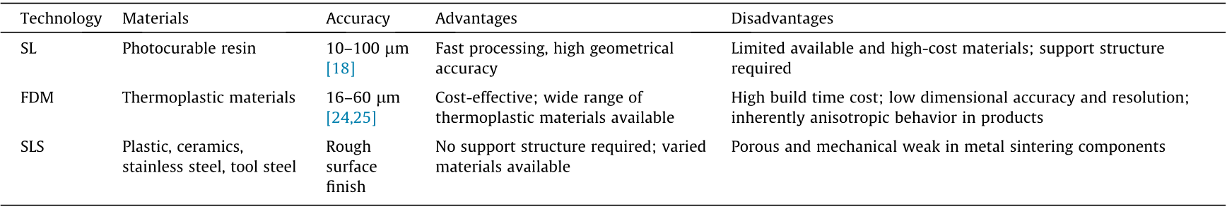
Additive fabrication technologies include stereolithography (SL), fused deposition modeling (FDM), selective laser sintering (SLS), laminated object manufacturing, laser engineered net shaping, Sanders rapid prototyping machines, rapid freeze prototyping, and multi-materials laser-assisted densification [16]. The three most primary technologies are SL, FDM, and SLS. SL, as the oldest AM technique, was the first entry into the rapid prototyping field during the 1980s. It has become one of the most popular and widespread technologies [17]. The minimum feature size ranges from 10 to 100 lm, which is roughly 10 times smaller than that of extrusion based FDM [18]. SL works by using a high-powered laser to convert photosensitive liquid into 3D solid plastic layer by layer. The second most prominent commercial AM technique is FDM, which creates a 3D object by extruding a melted thermoplastic filament and depositing it layer by layer [19]. The two most common materials used in FDM are acrylonitrile butadiene styrene and polylactic acid [20]. FDM has the advantages of a short cycle time, high dimensional accuracy, ease of use, and easy integration with different types of computer-aided design (CAD) software. SLS is a technology that creates 3D objects by fusing or sintering successive powdered materials using thermal energy supplied by a laser beam. SLS is the third most common method used by manufacturers following after SL and FDM [21]. A wide variety of materials with the characteristics of strength, durability, and functionality are available for SLS [22]. Polyamide 12 is the most commonly adopted material, with a market share above 90% [23]. Table 1 provides a comparison of SL, FDM, and SLS [18,24,25].
《Table 1》
Table 1 Comparison of printing features among SL, FDM, and SLS technologies.
《3. Additive manufacturing in orthoses manufacturing》
3. Additive manufacturing in orthoses manufacturing
Researchers have been interested in computer-aided prosthetic socket design since the early 1960s. Steps for the use of AM technologies in the fabrication of prostheses and orthoses have been proposed [26,27]. With advances in materials and decreased cost, the feasibility of AM technologies has been widely tested in recent studies. Studies [28–31] have outlined novel prosthesis and orthosis manufacturing methods utilizing body scanning, CAD, and AM technologies. SLS and FDM techniques have been used for ankle-foot orthoses production. Both methods required scanning of the foot and utilizing an ankle-foot orthosis model simulation [28,29]. Thus far, there has been limited feedback regarding post-clinical outcomes from patients; however, investigations from laboratory testing and questionnaires have provided some estimation of outcomes.
Various types of customized foot orthoses have been fabricated using AM technologies, and have been compared with traditional fabricated products through gait observation and subjective evaluation of fit and comfort [32–34]. Foot functional insoles for runners were designed to be glove-fit; they were then manufactured using SLS technology and compared with commercially available insoles in terms of comfort and biomechanical parameters [33]. The threemonth test showed that the AM-made insoles had better outcomes in both comfort and injury prevention. In another study, the stiffness of SLS orthoses made for passive-dynamic patients was made to match that of traditional ones through computational simulation and the use of destructive tests to guarantee reliability; the performance was then tested in patients walking. The outcome showed no difference from traditional orthoses [28]. In a function comparison of arch support cushions made using 3D printing, traditional fabricated orthosis, and running shoes without cushions, the arch height index was measured [35] and analyzed. The 3D-printed arch support cushion was found to increase the arch height index compared with un-cushioned shoes, but the result was still lower than the arch height index obtained with tradition fabricated orthosis.
AM-fabricated ankle-foot orthoses have been commercialized [36,37] and have been clinically applied for clubfoot [38] and rheumatoid arthritis [39], and to relieve peak pressure under metatarsals [40]. SLS-fabricated passive-dynamic ankle-foot orthoses made of Nylon 12, glass-filled Nylon 12, and Nylon 11 were tested in terms of energy dissipation characteristics and compared with a commercially available carbon-fiber ankle-foot orthosis [30]. Mechanical damping and destructive testing showed that Nylon 11 exhibited the least amount of energy dissipation, and was the only material with adequate stiffness. Following were Nylon 12 and glass-filled Nylon 12. An evaluation of SLS-made orthoses for rheumatoid arthritis patients showed similar outcomes in walking with traditional orthoses, and patients felt no difference in comfort and fit [39]. Foot orthoses with an adjustable element to relieve plantar pressure and an ankle-foot orthosis with adjustable stiffness were designed and fabricated using AM technology, and tested with a healthcare participant [40]. The results demonstrated that both AM-fabricated orthoses were able to satisfy the functional requirement. This study indicated the availability of AM for novel personalized orthotic device fabrication. The spatial temporal gait parameters and ankle kinematic parameters of anklefoot orthoses fabricated using SLS technology were compared with those of clinically accepted thermoplastic polypropylene orthoses [41] in eight subjects with unilateral drop foot. The results showed that both types of orthosis improved the gait performance in comparison with going barefoot, and no significant difference was found between the AM-fabricated and traditionally fabricated orthoses. These studies confirm the feasibility of the AM approach in foot/ankle-foot orthoses customization and indicate significant clinical potential.
《4. Additive manufacturing in prostheses manufacturing》
4. Additive manufacturing in prostheses manufacturing
A prosthetic socket, which acts as a coupling between the body and the prosthesis, should be designed to appropriately transfer and bear loadings. It should control stability during mobility without hurting the tissues of the residual limb, and satisfy the requirements of both function and comfort. The socket shape is not an exact replica of the residual limb. Soft tissues around the residual limb are not well-suited for load bearing. Improper load distribution during walking or other activities may cause discomfort or skin damage. Modification of the shape, considering the variations in regional load tolerances, is intended to distribute the loads effectively between the prosthesis and the residual limb.
In traditional manufacturing, a positive mold of the residual limb is necessary in the socket design process. Shape modifications are realized in both the shape wrapping and shape rectification of the positive mold. The process of shape modification uses a subjective trial-and-error approach that is extremely dependent on the experience of the designer. The quality of the design can be only assessed after fabrication. Further modifications are needed in most cases during the fitting process, until a successful fit is achieved. It is impractical to assess the performance of the design before fabrication in the traditional manufacturing approach.
In the early stages, the cost of a 3D-printed prosthetic socket exceeded the cost using traditional methods [42] and could not satisfy the requirements of strength and durability [43]. AM was thus not suitable for extended use until recent years. The socket of a transtibial prosthesis was fabricated using CAD and SLS technologies and was identical to the subject’s definitive socket [44]. The socket was assembled using the same foot as the definitive prosthesis, and showed improved comfort, greater step symmetry, and similar lower extremity joint function compared with the definitive prosthesis. A transtibial socket composed of an inner layer and outer layer coated with resin was designed using CAD systems and produced using FDM technology [45]. The prosthesis satisfied the amputee and prosthetist in terms of safe walking. The interface pressure between the stump and the socket was also found to fit the amputee. CAD and AM were used to fabricate a transtibial socket that was integrated with compliant features to reduce interface peak pressures over bony protuberances [46,47]. Measurement in a bilateral transtibial male amputee showed a reduction in contact interface pressure during the stance phase of the gait in comparison with a conventional socket. These studies indicate the feasibility of FDM in the design and manufacture of transtibial sockets.
《5. Finite-element analysis of prostheses and orthoses design and assessment》
5. Finite-element analysis of prostheses and orthoses design and assessment
In AM fabrication, a design is expected to be well fitted to the patient without further modification of the design. An assessment system that can predict and design an appropriate fit in advance of fabrication is necessary. Computational analysis provides a feasible tool for this purpose. Finite-element analysis was introduced to prosthetic socket and orthosis design in the late 1980s [48]. It is capable of providing stress distribution in the tissues of the human body and in components of the prosthesis or orthosis, determining the load transfer mechanism, and identifying biomechanical behaviors on the contact interface between the body and the prosthesis or orthosis. Topology optimization of the design based on finite-element predictions is a powerful approach to obtain the desired function performance [49].
A study proposed testing the breaking resistance of an AMfabricated ankle-foot orthosis under frequency and temperature loads using finite-element analysis [50]. In a study on the AM fabrication of passive-dynamic ankle-foot orthoses, finiteelement models of the orthoses were used to determine the cross-sectional strut dimensions [30]. To determine the optimized approach among different manufacturing methods, a comparison was conducted of the processes, materials, and material thicknesses while balancing cost, production time, and patient performance for various ankle-foot orthoses [6]. A function of multi-objective optimization algorithms was used for this comparison, which took three sizes of the ankle-foot orthoses as input. The performance was represented using metabolic rate, which was directly affected by the bending stiffness of the ankle-foot orthosis [51,52]. Finite-element analysis was used to identify the effects of material properties, thickness, and size on the stiffness of the device. The size-dependent variables were determined through regression functions based on finite-element analysis. Among traditional plaster casting, SLS, and FDM, FDM was found to be the optimal process. FDM was the fastest process—although it incurred a small increase in cost in comparison with the plaster casting method—and maintained a comparable performance. AM was used to design an ankle-foot orthosis to improve the condition of excessive heating and sweating. An evaluation of the performance of the orthosis with extra space for air circulation was conducted based on finite-element analysis [53].
An article [54] reviewed research on socket biomechanics including socket pressure measurement, friction-related phenomena and associated properties, computational modeling, and tissue responses to external loads on the interface. It stated in summary that biomechanical understanding has advanced the science of socket fitting, but has not led to sufficient alteration in clinical practice. A donning procedure was simulated using explicit finite-element models of the residual limb and the prosthetic socket in order to investigate the pressure and shear stresses in the longitudinal and circumferential directions on the interface [55]. A finite-element model of a prosthetic socket was developed with simplifications, and was used to estimate the safety factor [47]. To evaluate the comfort and fit of a transfemoral prosthetic socket, finite-element analysis was conducted with models of the residual limbs and sockets. Interface pressure in two standing loading conditions was analyzed [56] and demonstrated similar pressure distribution between different types of sockets. The predicted pressure was highly correlated to that in the experiment. In another study, the friction conditions, stresses in soft tissues, and shear stresses on the interface were simulated [57]. To identify the risk of deep tissue injury, finite-element analysis was conducted to simulate the loading-bearing conditions of a transtibial patient wearing a prosthesis [58,59]. Internal strains, strain energy density, and stresses in muscle flaps were analyzed, which indicated that the patient-specific modeling method was feasible for understanding the etiology of deep tissue injury. In finiteelement investigations on prostheses and residual limbs, the effects of the interaction between the bone and soft tissue on the stress-strain state of the residual limb were analyzed [60]. The study concluded that friction between the bone and soft tissue has a significant impact on the stress-strain predictions. An important problem of a prosthetic socket is that it is difficult to release heat; thus, heat release should be optimized during socket design. Finite-element analysis was conducted for thermal analysis in a transtibial residual and prosthesis. The impact of the thermal conductivity of the liners on the heat dissipation ability of the prosthesis was evaluated, and it was found that thermal conductivity affected the temperature of the skin of the residual limb [61]. In addition to prosthetic socket design and evaluation, computational analysis has been used to evaluate the performance of a carbonfiber ankle-foot prosthesis [62].
We have conducted biomechanical measurements and simulations in the design of prostheses and orthoses, including foot orthoses for flatfoot, transtibial prostheses, and face orthoses for burn rehabilitation. To explore the transtibial prosthesis interface biomechanics during gait, finite-element models of a residual limb and a transtibial prosthetic socket were developed from a reconstruction of the magnetic resonance images of a transtibial amputee patient and the socket (Fig. 1). The models allowed slip on the contact interface between the residual limb and the socket, which was considered to be pre-stress after the donning procedure and the effects of material inertia. With the application of boundary and loading conditions obtained from gait analysis, a gait cycle was simulated. Contact pressure and shear stress on the interface were analyzed and compared with and without material inertia effects. Fig. 2 shows the interface contact pressure distribution at 20% of the gait cycle and the peak pressure during the entire gait cycle in the areas of the middle patella tendon, the lateral tibia, and the medial tibia. Fig. 3 shows the shear stress distribution in the longitudinal and circumferential directions at 20% of the gait cycle and the resultant shear stress in the middle patella tendon, the lateral tibia, and the medial tibia areas.
《Fig. 1》

Fig. 1. Finite-element model of the residual limb and transtibial prosthetic socket.
《Fig. 2》
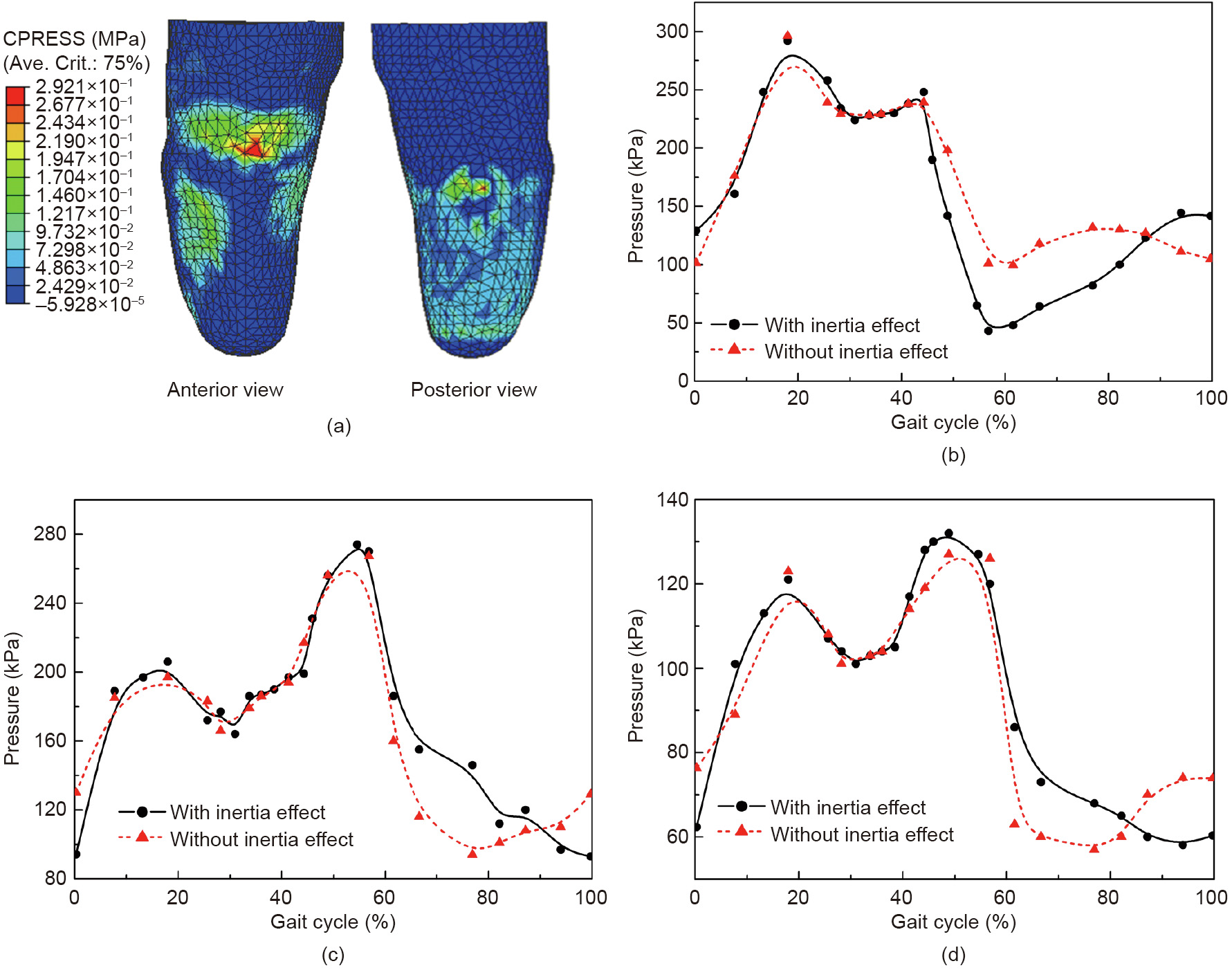
Fig. 2. Contact pressure in the residual limb. (a) Pressure distribution at 20% of the gait cycle; (b) peak pressure in the middle patella tendon area; (c) peak pressure in the lateral tibia area; (d) peak pressure in the medial tibia area. CPRESS: contact pressure. Ave. Crit. means the results are averaged from elements that values differ within 25% from surrounding elements.
《Fig. 3》
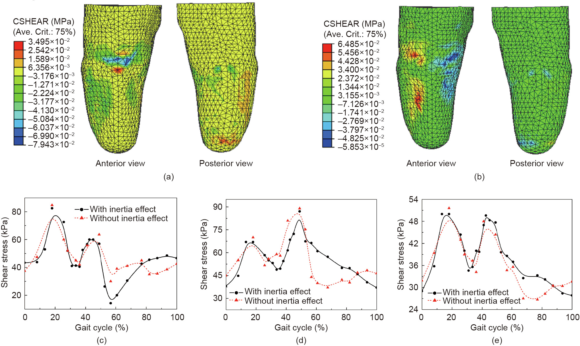
Fig. 3. Shear stress on the contact interface of the residual limb. (a) Longitudinal and (b) circumferential shear stress at 20% of the gait cycle; (c) reluctant shear stress in the middle patella tendon area; (d) reluctant shear stress in the lateral tibia area; (e) reluctant shear stress in the medial tibia area. CSHEAR: frictional shear stress.
The curves of the contact pressure and shear stress show a similar double-peaked shape during the stance phase. The average differences in the interface shear stress in cases with versus without consideration of material inertia are 8.4% and 20.1%, respectively, in the stance and swing phases, which indicates that it is preferable to consider the material inertia effect in dynamic finite-element analysis.
In the modeling stage before finite-element analysis, a 3D scanner and CAD software were used to obtain a digital model of the relative part of the human body. A manual process and finite-element analysis are performed on the digital model to produce a printable 3D model. The time consumption of the manual process depends on the prescription of the orthotist or prosthetist and the experience of the technician. The model structures and simulation conditions determine the complexity of the iteration of the simulation and the consumption of computational resources and time, which can vary widely from case to case. Limited data are available regarding the time and human resource costs of this design procedure, and regarding the entire procedure of AM manufacturing [13].
《6. A systematic framework of the additive manufacturing process》
6. A systematic framework of the additive manufacturing process
These finite-element models provided valuable information on the prediction of the performance of prostheses and orthoses. However, these advanced modeling technologies have not yet altered the clinical and commercial state. There is a lack of a mature systematic framework of the entire AM procedure, including the computational analysis process. Researchers has proposed a framework that included the scale and alignment of orthoses [63]. Although this framework demonstrated the dimensional accuracy of AM technology, biomechanical optimization of the design was not included. A novel virtual functional prototyping process, consisting of digital model parameterization and finiteelement analysis, was developed to quantitatively tune and predict the functional characteristics of a passive-dynamic ankle-foot orthosis [64]. The design was then fabricated via FDM technology using medical-grade polycarbonate, and the performance was tested. The bending stiffness, dimensional accuracy, and manufacturing precision were found to be satisfying. However, this process was a combination of technologies rather than a systematic framework.
We propose a framework, shown in Fig. 4, to manage the AM procedure from the initial conception to the final adaptable products. Any type of scanning or imaging of the surface shape should be compatible with the imaging and scanning package. Data with detailed internal structures such as computed tomography, magnetic resonance imaging, and ultrasound, and point-cloud surface data such as photogrammetry, laser scanning, and millimeter wave would be acceptable for reconstruction into geometries [65]. The 3D geometry of the affected body part is reconstructed from the scanning and imaging data, based on which the physical model of an initial design of the prosthesis or orthosis is produced. Digital manipulation based on the experience of prosthetists or orthotists and basic design principles is conducted to obtain the initial design model. Models of the body part and the initial design of the prosthesis or orthosis are further developed into finite-element models and assembled to simulate wearing and motion activities. A physical model of the initial design of the prosthesis or orthosis is used for a fitting to the patient and for measurement experiments. Measurements of the biomechanical parameters on the contact interface, including contact pressure, shear force, temperature, and humidity, would be an essential part of the experiments. Motion analysis with patients wearing the prosthesis or orthosis is conducted to evaluate the kinetic and kinematic behaviors, which would provide boundary and loading conditions for the computational simulation. The measurements on the contact interface are compared with the results from the computational analysis to validate the finite-element models.
《Fig. 4》

Fig. 4. A systematic framework for the AM procedure.
Besides the boundary, loading, and validation conditions provided from experiments, tissue and material properties are necessary input for the computational analysis. The material properties of the products are determined when the material for the design is confirmed. Tissue properties, especially those of soft tissues, are a current challenge in the biomechanical field. An ultrasound indentation appliance provided an easy and quick way for in vivo measurement of the biomechanical properties of soft tissues [66]. Computational simulation can provide insight into the inner body, contact behavior on the contact interface, and biomechanical information of the prosthesis or orthosis. These values, combined with the parameters measured during the experiments, would be analyzed and compared in order to determine unreasonable performance, such as stress concentration, excessive loading in a loading-sensitive area, or limited deformation during motion. If the finite-element analysis predicted overall unreasonable performance, structural or material modification would be done on the model of the initial design of the prosthesis or orthosis. The subsequent finite-element model would be re-meshed and reassembled with the model of the human body part, and the same steps would be repeated until the parameters showed a reasonable and satisfying overall performance. If the finite-element analysis results indicated only local unreasonable behavior, such as stress concentration in a local area, digital manipulation would be done to the specific area, followed by re-meshing, re-assembly, and motion simulation. Finite-element analysis can respond rapidly to such model modifications. The optimization cycle would be repeated until the computational prediction showed reasonability in all investigated parameters and was consistent with the experimental measurements. Topology optimization would be performed to redistribute materials in order to lighten the products, while satisfying the desired strength.
Anisotropic behavior induced by weak bonding between layers and structured porosity [67], which are imposed by the building direction [68], is of particular concern in the design stage [69]. The relationship between the microstructure and the orthotropic behavior of a 3D-printed sample was analyzed based on finiteelement analysis. The results revealed differences in mechanical behavior between different printing orientations [69] and microstructures [70]. The optimized model of the prosthesis or orthosis would be transferred to a printable digital model, usually in .STL format. In the design of a printable digital model, the printing orientation should be chosen to satisfy the strength, time cost, and accuracy requirement of the product. In some cases, a contour design for the printable digital model is needed to create strong but lightweight parts. Post-processing is necessary in most cases, both before and during the fitting procedure.
At the very beginning of the product design, the optimization procedure might continue for several cycles, during which abundant data would be accumulated. General regulations could be extracted from the data, which could make the initial design closer to reasonability, and the structure or material modification more efficient and specific. Various technologies for product fabrication are available. The key factor in the application of these technologies is that the products must satisfy the requirements of functionality, comfort, and aesthetics, while keeping the cost competitive.
The framework for the AM industry is to streamline the production processes, permitting faster production and consistent qualities for customization. Although AM manufacturing is superior to the traditional approach in the procedure of "manufacturing,” it has not been widely commercialized and applied in prosthetic and orthotic clinics because of existing limitations in the stages of a mature systematic framework. One notable problem is that, in comparison with traditional procedures, the implementation of pre-manufacturing analysis and simulation requires extra skills from experienced prosthetists [71]. Additional computational resources such as professional software and equipment are necessary [27,53]. The establishment of a database for AM design procedures requires long-term accumulation; during this period, the time cost of the product model design cannot be strictly evaluated. Most studies on the application of AM technologies have not practically determined the time consumption and extra cost of the entire procedure; however, making one specific design using current engineering software and technologies has a significantly higher cost than traditional fabrication [13]. Moreover, the evaluation of AM products is insufficient. Post-clinical outcomes, reliability, and durability have mostly been evaluated through laboratory testing, rather than from patient feedback. The evaluations have not been comprehensive enough to cover all aspects, such as compensation from muscle activities and patient perceptions. Undetected effects and long-term feedback from patients are still limited for ensuring the performance of AM orthoses and prostheses.
《7. Closing remarks》
7. Closing remarks
In this work, we have attempted to cover a broad spectrum of the development and influencing factors of AM in the field of prostheses and orthoses, including fabrication technologies, methodologies of design, materials feasibility and application, functional evaluation, and current challenges regarding these aspects. Based on the literature review, one of the key challenges in the expansion of AM application for prostheses and orthoses is the lack of a framework of the AM procedure that covers the process from the initial conception to the final adaptable products. Another key factor is the need to satisfy the requirements of function and comfort, which depend on accurate biomechanical prediction and optimization of the design before printing. We have proposed a systematic framework that covers the process from the scanning of the affected body part to the 3D printing of the final product design. An optimization cycle based on computational analysis is included in the framework.
Intellectual property rights could be a key issue requiring future change since AM allows products to be easily replicated based on digital representations. Thus, AM manufacturing could be more difficult to defend than conventional methods. Novel forms of intellectual property such as Creative Commons licenses, sharing licenses, or the open source concept applied to hardware could become promising alternatives [7,9]. In addition, confidential and ethical measures, such as digital models of patients’ body parts or individually characterized products, should be discussed and strictly protected, especially for cases that allow public downloads [72].
A great deal of time and effort may be needed in the current stage of applying AM technologies in the orthoses and prostheses industry, considering the extra requirements on resources and human resource costs in comparison with traditional procedures. With the explosion and maturity of AM technology, consumers can not only modify existing designs, but also create or co-design depending on their own demands. A low-cost printer and advanced AM technologies could drastically change the product design pattern.
《Acknowledgements》
Acknowledgements
This study is supported by National Key R&D Program granted by the Ministry of Science and Technology of China (2018YFB1107000), the NFSC projects granted by the National Natural Science Foundation of China (11732015 and 11972315), and the General Research Fund granted by the Hong Kong Research Grant Council (PolyU152065/17E).
《Compliance with ethics guidelines》
Compliance with ethics guidelines
Yan Wang, Qitao Tan, Fang Pu, David Boone, and Ming Zhang declare that they have no conflict of interest or financial conflicts to disclose.


 京公网安备 11010502051620号


