
《1. Introduction》
1. Introduction
Craniomaxillofacial reconstruction is a common surgical operation that has been extensively used in tumor removal and trauma care. Surgical implants are conventionally massproduced in standard forms that need to be manually bended to match the individual patient’s bone anatomy during surgery. Bending these plate-shaped implants is time-consuming and error-prone, especially for inexperienced surgeons [1]. In addition, in order to achieve the desired shape, repetitive bending is often necessary, which induces internal stress concentration. It has been shown that the stressed implants may suffer from fatigue under in vivo masticatory loading, resulting in various complications such as plate fracture, corrosion, screw loosening, and bone resorption [2,3].
In recent years, the use of three-dimensional (3D)-printed patient-specific craniomaxillofacial reconstruction implants has been increasingly reported. For example, Li et al. [4] reported 18 cases of jaw reconstruction (ten maxillary reconstruction and eight mandibular reconstruction) using personalized 3D-printed titanium plates. Singare et al. [5] reported a method for the design and fabrication of a 3D-printed titanium implant for repairing mandible bones. The implant was designed based on a 3D model from computed tomography (CT) scanning data with manual modification. Li et al. [6] reported a study on the use of 3Dprinted personalized titanium implants for maxilla in orthognathic surgery, in which eight patients with different degrees of maxillofacial deformities participated. Different materials and microstructures have also been studied. For example, Zhang et al. [7] made a ceramic mandible with a macro- and micro-porous surface structure using inkjet 3D printing. Diao et al. [8] studied the effect of smaller pore sizes (below 400 lm) in 3D-printed bioceramic scaffolds on bone regeneration and biomechanical behavior. Rotaru et al. [9] investigated whether a calvaria reconstruction could be achieved using 3D-printed implants and examined the possible complications that might result. Three years later, they described a zygomatic reconstruction case utilizing a 3D-printed implant [10]. In Ref. [11], 3D printing was used to fabricate a personalized prosthesis to successfully treat left unilateral temporomandibular joint ankylosis in a 12-year-old female. A total replacement surgery was performed. In Ref. [12], a Korean team demonstrated the efficacy of custom-made 3D-printed titanium implants for reconstructing skull defects. They reported a total of 21 cases (11 females and 10 males, aged 8–62 years with a mean age of 28.6 years). In Ref. [13], patient-specific functional implants were utilized in combination with a fibula free flap for several mandible reconstruction cases.
Comparisons between 3D-printed implants and traditional manufacturing implants have been documented in a number of studies. For example, Wilde et al. [14] compared 3D-printed reconstruction plates with conventional hand-bended plates in regard to their biomechanical characteristics. They concluded that the former offer higher stability and rigidity than the latter. Since 3D-printed implants and traditional manufacturing implants use the same material (e.g., pure titanium), their biocompatibility is the same, although surface treatment can make a difference, as discussed in the next section. The most significant advantage of a 3D-printed implant is the time of surgery and clinical outcome. Ref. [15] provides a rather detailed review of 3D-printed implants. First, the duration of preoperative complications between the onset of a cranial defect and the cranial plate insertion is a significant complaint among patients. The traditional cranioplasty manufacturing process takes up to four weeks, and plates are typically ordered, manufactured, and sterilized before the surgery is scheduled [16]. In comparison, it takes only a few days to make an implant using 3D printing. In addition, 3D printing shifts the manufacture of cranial plates to a later stage in the application process chain. A digital model of the cranial plate can be produced within hours by an experienced prosthetist, and can then be viewed by surgeons and other clinicians on the same day. Once a surgical date is confirmed, the 3D printing can start, and a plate can be completed and delivered for sterilization within one or two weeks [17]. By shifting the manufacturing to post-surgical scheduling, the likelihood of a plate no longer being required is reduced, cutting waste. Most importantly, plates that are manufactured using both fully and semiautomated digital workflows show superior accuracy over conventional hand-manufactured plates, reducing the need for adaption during surgery [18]. Greater surgical duration has been associated with poorer patient outcome [19] and, while it is difficult to unpick the association among operative time, complications during surgery, and postoperative complications, minimizing surgical time and related anesthesia duration is well recognized as an important consideration in many surgical fields [20,21].
Nevertheless, it is notable that the existing research mainly focuses on the fitting of the individual patient’s bone contour. While this facilitates the surgical procedure by reducing surgery time and improving surgical accuracy, many other issues have not yet been addressed, such as implant quality.
We believe that a 3D-printed patient-specific craniomaxillofacial reconstruction implant should be made and used in a systematic manner. Therefore, we propose a systematic approach, shown in Fig. 1. This approach consists of three parts: design, fabrication, and clinical application. It should be noted that the surgeon and design engineer will work collaboratively in various steps, in order to ensure the quality of the implant. Moreover, a patient-specific record file will be generated and stored in the cloud, and can be assessed by authorized persons whenever needed.
The rest of the paper is organized as follows: Section 2 describes the design procedure, and Section 3 describes the fabrication procedure. Section 4 presents the clinical study and discussions. Finally, Section 5 contains conclusions.
《2. The design procedure》
2. The design procedure
As shown in Fig. 1, the design consists of three parts: ① the implant design; ② the computer simulation, based on which the design can be optimized; and ③ the auxiliary tool design.
《Fig. 1》

Fig. 1. The proposed systematic approach for making 3D-printed patient-specific implants for craniomaxillofacial reconstruction.
《2.1. Implant design》
2.1. Implant design
The design of a patient-specific craniomaxillofacial reconstruction implant starts with the CT scan data. At present, commercial CT systems have the capability to build a 3D model with accurate dimensions. However, surgeons are not trained to use computeraided design (CAD) software (Autodesk Inc., USA) to design 3D implants. Therefore, it is desirable to develop a simple software module so that surgeons can design an implant by means of simple point-and-pick operations. Fig. 2 shows the interface of our design module, which was developed on Solidworks® (Dassault Systemes Global Services Pvt. Ltd., France). It has the following functions:
• Read the 3D CT model (Fig. 2(b));
• Specify the cross-sections of the implant (Fig. 2(c));
• Specify the key points on the 3D CT model, including the center of the crew holes, the turning points, the twisting points, the branching points, etc. (Fig. 2(d)); and
• Generate a record on the cloud (Fig. 2(e)).
With the proper inputs, an implant design will be automatically generated. It should be noted that the design only gives a rough shape of the implant. The surgeon can contact the corresponding engineer to add on engineering design features, such as a fillet, chamfer, and other details. It is well known that human anatomy is complex, and the patient’s condition could change over time. As a result, it is often necessary to have several meetings to sort out detailed design issues. With our design module, these meetings can be held online, saving a great deal of time and effort. For each design, a unique record will be generated on the cloud that documents not only the design, but also the fabrication and the surgery. This record will follow the patient for life and will be accessible to authorized persons.
《Fig. 2》

Fig. 2. Our design module, which was developed on Solidworks®, will help surgeons to design the patient-specific implant. (a) The interface of our design module; (b) read a 3D CT model; (c) specify the cross-section of the implant; (d) use point-and-pick key points to generate the implant design; (e) generate a patient-specific implant record.
As an example, Fig. 3 shows several implant designs. In practice, it is sometimes necessary to use fibula to assist the craniomaxillofacial reconstruction. In this case, as shown in Fig. 4, the design of the implant should follow a more elaborate procedure including establishing build volume placement, adding support material, slicing, and creating a build path. It should be pointed out that, at present, the design of a 3D-printed patient-specific implant largely depends on the experience of the surgeon. Our design module helps surgeons and engineers to work collaboratively. In addition, the designed implant can be conveniently simulated, as described in the subsequent section. The advantages of this method are visualization and accuracy.
《Fig. 3》
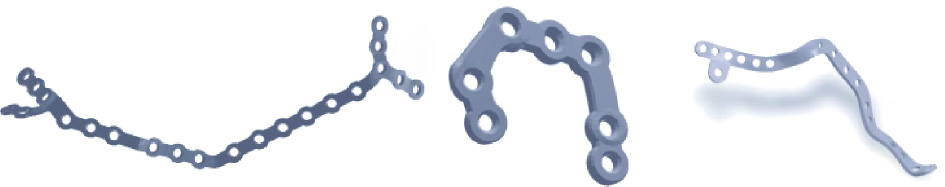
Fig. 3. Some samples of patient-specific craniomaxillofacial implant designs.
《Fig. 4》

Fig. 4. A sample of craniomaxillofacial reconstruction with fibula insertion. (i) A 3D CT model of the mandible; (ii) the fibula bone flap is harvested in one or multiple segments, which are aligned in the necessary positions to restore the mandibular contour; (iii) computer simulation of the mandible osteotomy and fibula insertion; (iv) the implant path is first delineated by drawing a curve on the outer surface of the reconstructed mandible; (v) discrete screw holes are placed along the implant; (vi) the patientspecific surgical implant is generated.
《2.2. Computer simulation》
2.2. Computer simulation
After the initial design, finite-element modeling (FEM) is carried out to evaluate and improve the design. Fig. 5 shows an example. First, we designed a "V”-shaped implant to be used to repair the broken mandibular (Fig. 5(a)). Second, we built an FEM model with three kinds of loading conditions: the bite on the implant side (Fig. 5(b)), the incisor (Fig. 5(c)), and the bite on the uninjured side (Fig. 5(d)). Next, Figs. 5(e)–(g) shows the corresponding von Mises stress distribution of the implant, while Figs. 5(h)–(j) shows the corresponding von Mises stress distribution of the mandibular. It is noted that the greatest stress occurs when biting on the implant side. However, the maximum stress (109 MPa) is below the tolerance of the bone (120 MPa) and is thus safe.
Based on the FEM simulation, design engineers can help the doctors to further optimize the design. Due to the complexity in setting up an FEM, the simulation process has not yet been automated. In other words, doctors must work with design engineers to carry out the simulation and optimization.
《Fig. 5》

Fig. 5. Design and FEM analysis of a mandible repair implant. (a) "V”-shaped implant; FEM model with three kinds of loading conditions: (b) the bite on the implant side, (c) the incisor, and (d) the bite on the uninjured side; the corresponding von Mises stress distribution of the (e)–(g) implant and (h)–(j) mandibular.
《2.3. Auxiliary tool design》
2.3. Auxiliary tool design
During craniomaxillofacial reconstruction surgery, a number of auxiliary tools are needed, including surgical guides, fixation screws, and so forth. Fig. 6 shows a sample of a surgical guide, which is used to position the osteotomized bone and the implant prior to the final fixation. At present, the design of such auxiliary tools largely depends on the experience of the surgeon. Their fabrication can be done by 3D printing, either through laser stereolithography (SLA) or fused deposition modeling (FDM). We are working on a systematic approach for designing and manufacturing the implant and auxiliary tool together, which will be presented in a separate paper.
《Fig. 6》
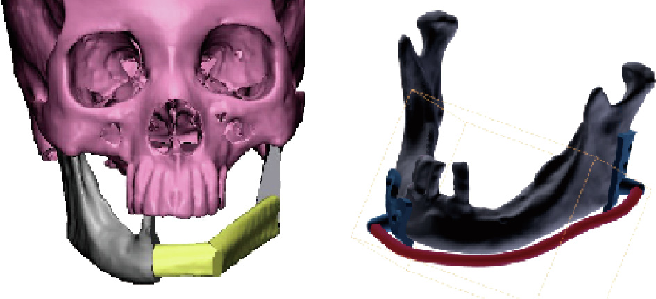
Fig. 6. An example of a surgical guide for mandibular reconstruction.
《3. Fabrication》
3. Fabrication
Patient-specific craniomaxillofacial reconstruction implants are made using a selective laser melting (SLM) 3D printing process. However, simply printing the implant cannot guarantee its quality. Instead, a quality-control procedure is needed. As shown in Fig. 1, this procedure consists of three parts: quality control of the powder material, 3D printing of the implant, and post-processing of the implant.
《3.1. Quality control of the powder material》
3.1. Quality control of the powder material
It is known that during the SLM 3D printing process, titanium powders are melted and then solidified point by point, forming the implant. It is clear that the quality of the powder material has a significant effect on its geometry, dimensional accuracy, surface quality, and mechanical properties. In the printing process, unused powders can be recycled and reused. It should be noted that repeatedly used material has been exposed to hazards including heat, oxygen, humidity, and ultraviolet light, which alter its properties. Table 1 shows a comparison of the chemical compositions of virgin powder and repeatedly used powder. As shown in the table, after 15 repetitions of 3D printing, a significant change has occurred. In particular, the oxygen content increases from 0.11% in virgin powder to 0.15% in powder after 30 recycles. Considering that the oxygen content quality standard is 0.15%, 30 recycles is a limit.
《Table 1》
Table 1 A comparison of the chemical compositions of powder material in different stages of the SLM 3D printing process.

Fig. 7 shows scanning electron microscopy (SEM) images of the virgin powder and a repeatedly used powder. As shown in Fig. 7, after 15 recycles, the powder suffers from shape distortion as well as the so-called "satellite effect”—that is, smaller powder granules are sticking to the larger granules. These issues will affect the quality of the printing process. In other words, after 15 recycles, the properties of the powder material should be checked, including the particle shape, particle size and size distribution, particle porosity, powder flowability, powder density, surface area, and chemical composition.
《Fig. 7》

Fig. 7. SEM images of the powder material. (a) Virgin powder; (b) repeatedly used powder after 15 recycles.
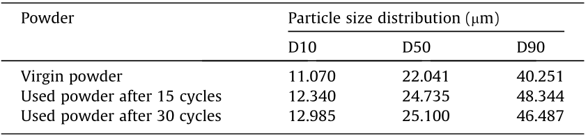
Table 2 provides a comparison of the particle size distribution of virgin powder and repeatedly used powders measured using a Hydro 2000MU(A) laser particle analyzer (Malvern Panalytical Ltd., UK). The measurement follows the Chinese National Standard GB/T 19077–2016. In the table, the column under D10 represents the particle diameter corresponding to 10% of the cumulative undersize distribution. The column under D50 represents the median particle diameter—that is, 50% of the particles are smaller than this diameter and 50% are larger. The column under D90 represents the particle diameter corresponding to 90% of the cumulative undersize distribution. As shown in Table 2, after repetitive usages, the particle size increases. However, the size distribution does not have a significant change. Thus, the powder can be cleaned, reconditioned, and reused again.
《Table 2》
Table 2 A comparison of the particle size distribution.
《3.2. Control of the 3D printing process》
3.2. Control of the 3D printing process
As mentioned in the previous section, the patient-specific implants are printed using SLM 3D printing. A number of companies produce SLM 3D printing machines. In our study, we used a commercial SLM machine (Mlab cusing 200R, Concept Laser GmbH, Germany). It has a number of parameters that can be tuned, including the laser power, laser scanning speed, step size (i.e., the width of the laser seam), and layer thickness. To ensure product quality, these parameters must be carefully tuned. Fig. 8 shows the density of the 3D-printed parts against these parameters. As shown in the figure, the density of the part increases with an increase in laser power. With an increase in scanning speed, the hatch distance and layer thickness increase, while the density decreases. In other words, in order to ensure high density, it is desirable to use a high laser power, low scanning speed, short hatch distance, and small layer thickness. Fig. 9 shows a part printed using two sets of different parameters. These micro-CT images reveal that the difference is significant. The former (laser power is 100 W, scanning speed is 375 mm·s-1 , and layer thickness is 50 μm) suffers from several micro-cracks, as indicated by white markers (Fig. 9(a)). With an increased scanning speed but a reduced layer thickness, the latter (laser power is 100 W, scanning speed is 475 mm·s-1 , and layer thickness is 45 μm) shows no cracks (Fig. 9(b)).
《Fig. 8》

Fig. 8. Density of 3D-printed parts against key process parameters. (a) Laser power; (b) scan speed; (c) step size; (d) layer thickness.
《Fig. 9》

Fig. 9. Micro-CT images of a part using two sets of different parameters. (a) Laser power = 100 W, scanning speed = 375 mm·s-1 , and layer thickness = 50 μm; (b) laser power = 100 W, scanning speed = 475 mm·s-1 , and layer thickness = 45 μm.
《3.3. Post-processing》
3.3. Post-processing
The post-processing of a 3D-printed part includes removing the supports, deburring, heat treatment, and surface treatment. Removing the supports and deburring is rather straightforward. Thus, we will focus on the heat treatment and the surface treatment herein.
3.3.1. Heat treatment
It is known that the microstructure of the titanium parts made by SLM 3D printing may contain some lath martensite [22,23]. While it is hard, its durability is not as good as its forging counterparts. Therefore, heat treatment becomes necessary. In experiments, the parts are encapsulated in quartz tubes and vacuumed to 10-3 Pa, and then annealed at the temperature of 800 °C. Fig. 10 shows the change in the microstructure of the parts during the heat treatment process. Specifically, Fig. 10(a) shows the martensite microstructure of a 3D-printed part. Fig. 10(b) shows the microstructure of the part after being heat treated for 30 min; transformation of the martensite to an equiaxed microstructure is appearing. Fig. 10(c) shows the part after being heat treated for 1 h; the equiaxed microstructure becomes predominant. Consequently, the part will have better plasticity, high impact toughness, and low notch sensitivity.
《Fig. 10》

Fig. 10. SEM images showing the change in microstructure during the heat treatment process. (a) A 3D-printed part with martensite structure; (b) when heated to 800 °C for 30 min, an equiaxed microstructure starts to appear; (c) when heated to 800 °C for 1 h, the equiaxed microstructure becomes predominant.
Fig. 11 shows the results of tensile tests of three different parts: the part made by forging, the part made by 3D printing, and the part made by 3D printing with heat treatment. For each part, ten samples were measured; the standard deviation is marked by a bar. It is seen that the mechanical properties of the part made by 3D printing with heat treatment are closer to those of the part made by forging than unheated parts.
《Fig. 11》

Fig. 11. The effect of heat treatment was investigated by analyzing the mechanical properties (a) tensile strength, (b) yield strength, and (c) elongation of three kinds of titanium samples prepared by different processes. A: forging (in blue); B: 3D printing (in orange); and C: 3D printing with heat treatment (in green).
3.3.2. Surface treatment
It is known that the bounding between the bone and the implant is affected not only by the material but also by the surface condition of the implant. Consequently, a number of surface treatment methods have been developed to construct various micro–nano surface textures, such as micro-arc oxidation [24], the plasma spray method [25], biomimetic deposition [26], the sol–gel process [27], the electrophoretic method [28], and electrochemical deposition [29–31]. The proper surface condition can promote osteoblastic activity, resulting in better osseointegration, which assists in both a fast recovery and long-term stability. Fig. 12 shows a set of experimental results. Fig. 12(a) shows a 3D-printed part without surface treatment, Fig. 12(b) shows the part with sandblast polishing, and Fig. 12(c) shows the part with micro-arc oxidation. Fig. 13 shows the surface microstructures of these parts and Fig. 14 shows their anode polarization curves, which are a measure of their resistance to causticity. As shown in the figures, micro-arc oxidization improves the corrosion resistance of titanium greatly and is therefore recommended.
《Fig. 12》

Fig. 12. Samples treated with different surface treatment technologies: A 3D-printed part (a) without treatment, (b) with sandblast polishing, and (c) with micro-arc oxidation.
《Fig. 13》

Fig. 13. The surface morphology of the parts: (a) 3D-printed part; (b) the part with sandblast polishing; and (c) the part with micro-arc oxidation.
《Fig. 14》

Fig. 14. Electrochemical corrosion polarization curves of the parts with different surface treatments in simulated body fluid (SBF) at (310 ± 1) K. I: current.
《4. Clinical applications》
4. Clinical applications
The clinical procedure is straightforward. As shown in Fig. 1, it consists of three parts: cleaning and sterilization, surgery, and postoperative rehabilitation follow-up.
From December 2016 to June 2019, we performed a total of 35 patient-specific craniomaxillofacial reconstruction surgeries in the Queen Mary Hospital, Hong Kong, China [32]. The mean time spent for surgery preparation, implant design, and implant fabrication (including 3D printing, post-processing, and testing) was about 40 h. The operation was greatly simplified, and the patientspecific implants adapted to the anatomic bone contour without difficulty. No further intraoperative plate bending was required. No significant intraoperative adverse events occurred. Furthermore, based on the postoperative follow-up, no major failure events have been found.
Three specific cases are briefly described below. Case 1 is shown in Fig. 15. In this case, a 57-year-old female patient with right mandibular squamous cell carcinoma was treated. A 3D-printed titanium implant and resin surgical guides were used [33]. Case 2 is shown in Fig. 16. In this case, a 35-year-old female patient with ameloblastoma of the right mandible was treated. Case 3 is shown in Fig. 17. In this case, a 79-year-old male with squamous cell carcinoma of the right maxilla was treated. All cases involved harvesting vascularized bone grafts that were folded and fixed to form the bone-implant complex. The 3D-printed implants and surgical guides greatly facilitated these operations. It is expected that, with more experience gained, 3D printing for craniomaxillofacial reconstruction surgery will become more accessible and will pave the way for a new era of precision surgery.
《Fig. 15》

Fig. 15. Case 1. (a) CT showed an enhanced soft-tissue mass invading the right mandible. (b) The patient-specific implant was designed to fit the contour of the reconstructed mandible. (c) The flap was transferred to the defect side and fixed to the mandibular stumps through pre-drilled screw holes. (d) After surgery, the intra-oral soft tissue flap healed smoothly. The mandible was accurately restored. According to the color map from the CT, high accuracy was achieved when comparing the postoperative mandible with the preoperative virtually planned model.
《Fig. 16》

Fig. 16. Case 2. (a) In the virtual surgery, the bone lesion was clearly visualized and mandibular resection was planned to achieve clear margins. The cutting guides were designed to direct bone resection and screw hole drilling. The fibular bone was harvested and segmented to restore the mandibular defect. (b) The patient-specific implant was designed to fix the bone segments in stable occlusion. (c) The right vascularized fibular flap was harvested and segmented with the cutting guide. Two fibular segments were folded and fixed by the 3D-printed patient-specific implant. The bone-implant complex was transferred to the defect side and fixed to the mandibular stumps. (d) Based on the color map from the CT image, high accuracy was achieved. The area in which deviation was within 2.0 mm is marked in green.
《Fig. 17》

Fig. 17. Case 3. (a) The intra-oral image shows a huge ulcerated mass in the right maxilla with superficial necrosis. The bone resection was planned in virtual surgery and the patient-specific implant was designed to match the bone contour. (b) The right fibular flap was harvested with the aid of the cutting guide. The fibular bone segments were folded and fixed using the patient-specific titanium implant. (c) Based on the color map from the CT, high reconstruction accuracy was achieved. The postoperative facial profile was symmetrical and satisfactory.
For future research and development, some interesting ideas are worthy of discussion. First, several new implant materials have been proposed, such as magnesium, zirconia, cobalt–chromium alloys, and polyether ether ketone (PEEK), as reviewed in Ref. [34]. More recently, Guillaume et al. [35] proposed a new biodegradable material—poly(trimethylene carbonate) (PTMC) loaded with 40 wt% of hydroxyapatite—referred to as osteoPTMC. All these materials can be used for 3D printing without significant problems, and the approach presented here is applicable to all. Second, although it is feasible to 3D print large implants that have good biomechanical and biomedical compatibility, such implants are not bioconductive or bioactive in the human body. In comparison, grafted bones that afford abundant vessel networks are expected to promote better bone healing. Finally, it is beneficial to add slow-releasing antibiotics and/or growth factors to the implants, so as to accelerate the bone healing process. However, a detailed solution remains to be worked out.
《5. Conclusions》
5. Conclusions
In this paper, we presented a systematic approach for designing and making patient-specific implants for craniomaxillofacial reconstruction. Based on this approach, high-quality patientspecific implants can be designed, built, and successfully used in the clinic. From the discussions above, the following conclusions can be drawn.
(1) Patient-specific 3D-printed implants have several advantages for craniomaxillofacial reconstruction over traditional implants, including high geometrical accuracy, optimal biomechanical properties, a simplified surgical operation, and a shortened recovery time. With further technological advances, it is believed that this technology will become the mainstream approach.
(2) The key to the success of making patient-specific implants for craniomaxillofacial reconstruction is to follow a systematic approach, as shown in Fig. 1, including design (implant design, surgical guide design, surgical plan, etc.), fabrication (material quality control, 3D printing process parameter optimization, heat treatment, surface treatment, etc.), and clinical application (sterilization, surgery, and postoperative rehabilitation follow-up). The absence of any of these steps may reduce the success rate. In addition, training and practice are important.
(3) Although simplified, the design of a patient-specific implant is still largely dependent on the experience of the surgeon. FEM can help to optimize the design, but also relies on the experience of the engineer and the surgeon. Moreover, the design of auxiliary tools (e.g., for harvesting the fibular bone and sectioning it to fit the mandibular reconstruction) has not been thoroughly investigated. This will be a topic of future research.
《Acknowledgements》
Acknowledgements
The study was partially supported by the Innovative Scientific Team Research Fund (2018IT100212), Science and Technology Bureau, Fo Shan, Guangdong, China. It was also partially supported by the Health and Medical Research Fund (05161626), Food and Health Bureau, Hong Kong, China.
《Compliance with ethics guidelines》
Compliance with ethics guidelines
Ruxu Du, Yu-Xiong Su, Yu Yan, Wing Shan Choi, Wei-Fa Yang, Chunyu Zhang, Xianshuai Chen, Jianglin Ouyang, and Bitao Zhang declare that they have no conflict of interest or financial conflicts to disclose.


 京公网安备 11010502051620号


