

《1. Introduction》
1. Introduction
With the application of a polymer coating that contains and controls the release of antiproliferative drugs, drug-eluting stents (DES) have become the gold standard for interventional treatment of coronary artery disease to date [1–3]. However, the backbone materials of DES are non-degradable metal materials that will cage the vessel permanently, which may lead to several inherent drawbacks, such as late restenosis, stent thrombosis, and chronic inflammation, and may impede the restoration of physiological function [4,5].
Problems associated with DES have prompted the development of bioresorbable stents (BRS), which provide transient support and then disappear; thus BRS can reduce the risk of late stent thrombosis and avoid prolonged dual antiplatelet therapy [6,7]. The conventional manufacturing process for metal stents is laser micro cutting, which has also been applied in the processing of BRS. Stepak et al. [8] investigated the influence of laser parameters on the quality and geometry of polylactide-based polymer stents. Guerra et al. [9] explored the feasibility of a 1.08 μm wavelength fibre laser to cut polycaprolactone (PCL) sheets, as a feasibility study for stents manufacturing. Nevertheless, laser processing is a thermal process that may lead to thermal damage, such as heat-affected zones, micro-cracks, tensile residuals, and dross deposition [10,11]. More importantly, laser cutting, as a kind of subtractive manufacturing method, is not suitable for personalized customization.
It has been observed that additive manufacturing (also known as 3-dimentional (3D) printing) has evolved into a versatile technology and economical solution for medical applications and customizable fabrication. Kaesemeyer et al. [12] used a rapid stent fabrication system with an extrusion system and a four-axis motion system to fabricate bioresorbable polystatin stents comprising lactide, glycolide, caprolactone, and lovastatin (60:15:10:15 parts by weight). Park et al. [13] evaluated the properties of a 3D-printed drug-coated PCL stent that was implanted into the porcine femoral artery. Guerra et al. [10] presented a novel 3D additive manufacturing machine to produce BRS with PCL filament material, and investigated the effects of the process parameters on the stent’s features. Wu et al. [14] manufactured polylactic acid (PLA) stents with a negative Poisson’s ratio (NPR) structure using a commercial fused deposition modeling (FDM) printer and PLA filaments, and studied the radial compressive property of the PLA stent. Although the results of these studies were promising, limitations remain regarding the stent’s shape. The BRS fabricated in the aforementioned studies have a cylindrical shape and a consistent diameter. In addition, stents generally undergo longitudinal foreshortening (a contraction in the length of the stent as the stent dilates). Clinicians must select stents with a longer length than the length of the plaque geometry to be stented. However, the degree of radial expansion and the final length of stents vary from person to person. Thus, the selection of a stent relies on the experienced judgment of the physician, which may go wrong and lead to malposition of the stent. Even more seriously, too much foreshortening would generate friction between the stent end and the artery, which would injure the delicate endothelium [15].
In this study, we propose a method for fabricating cardiovascular stents; we also develop a novel screw extrusion-based 3D printing system that includes a newly designed mini-screw extruder. A novel design of a stent with zero Poisson’s ratio (ZPR) structure is introduced. Preliminary monofilament testing was conducted to investigate the fabrication parameters of the home-made extruder. Subsequently, stents with different materials, diameters, and geometric parameters were fabricated by changing the diameter, length, and shape of the mandrel. The surface morphology and the effects of geometric and fabrication parameters on the mechanical properties of the 3D-printed PCL stents were studied.
《2. Design of stents with a zero Poisson’s ratio structure》
2. Design of stents with a zero Poisson’s ratio structure
At present, the majority of commercially available stents have a Z-shaped sequential-rings structure. This kind of design consists of two parts: Z-shaped rings (known as ‘‘struts”) and connectors (known as ‘‘bridges”) [16]. The Z-shaped rings are meant to expand during deployment and to support the vessel from collapse after the withdrawal of the balloon catheter. The connectors give the stent the ability to travel through the curvature of the arteries.
To solve the longitudinal foreshortening problem, we designed a stent with a ZPR structure, as depicted in Fig. 1. The structure unit (Fig. 1(a)) is similar to the semi-re-entrant honeycomb structure reported by Attard et al. [17], which exhibits a ZPR property. The Poisson’s ratio ( ) is defined as the ratio of the transverse strain (
 ) and the axial strain (
 ) in the direction of the loading force. The Poisson’s ratio can be expressed as follows:

The structural unit of stent geometry can be defined by the following parameters:  represents the length of the inclined rib of the Z-shaped element;
  represents the angle of the Z-shaped element; h represents the length of the connector unit; and t represents the diameter (or width) of the strut. With the grid shown in Fig. 1(b) rolled up into a tube, as shown in Fig. 1(c), D represents the diameter of the stent and H represents the total length of the connectors. Here we introduce N1 and N2 as the number of structural units in the circumferential direction and axial direction, respectively.
《Fig. 1》
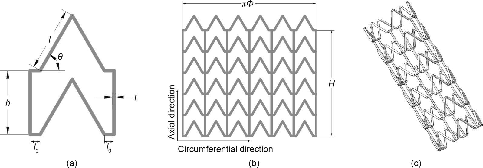
Fig. 1. Design of stent with ZPR structure. (a) The structural unit; (b) 2D expanded drawing of stent; (c) 3D model of stent.  : the half of the distance between the adjacent ribs.
When stents are dilated or compressed, the force is loaded in the radial direction. In Figs. 2(a) and (b), the angle changes with an increase of r (the radius of the stent), which may be written as follows:

where  The length of the stent in the radial direction (
 ) and longitudinal direction (
 ) is respectively given by

For loading in the radial direction (), which results in an infinitesimal change  in the angle , the strain in the
  direction can be expressed as follows:

where  is the deflection in
  direction and i = r, l.
As can be seen from Fig. 2(c), the change in the diameter of the stent when it is dilated mainly depends on the deformation of the inclined rib of the Z-shaped ring; therefore, we focus here on the deformation of the inclined rib under loading. An inclined rib of length  can be likened to a cantilever beam that is loaded and guided at one end and fixed at the other (Fig. 2(d)) [18]. The deflection of the rib in the x direction (
 ) can be decomposed into
  generated by the bending moment and
  produced by the component of the force F in the direction parallel to the rib. The deflection of the guided end and the deflection of the rib [19,20] are given by the following:

where E0 is the Young’s module of the material, I = πt 4/64 is the second moment of the rib, t is the diameter of the stent strut, and A = πt 2/4 is the area of the cross-section of the rib.
In this study, , t, and are usually set as 1.5 mm, 0.2 mm, and 60, respectively. Thus, we can find that

This indicates that in this study, is negligible relative to , which means that the deformation stretching of the rib can be viewed as negligible. Thus, the deflection of the rib in the x direction () can be written as follows:

The strain  along the x direction in Fig. 2(d) is given by the following:

《Fig. 2》
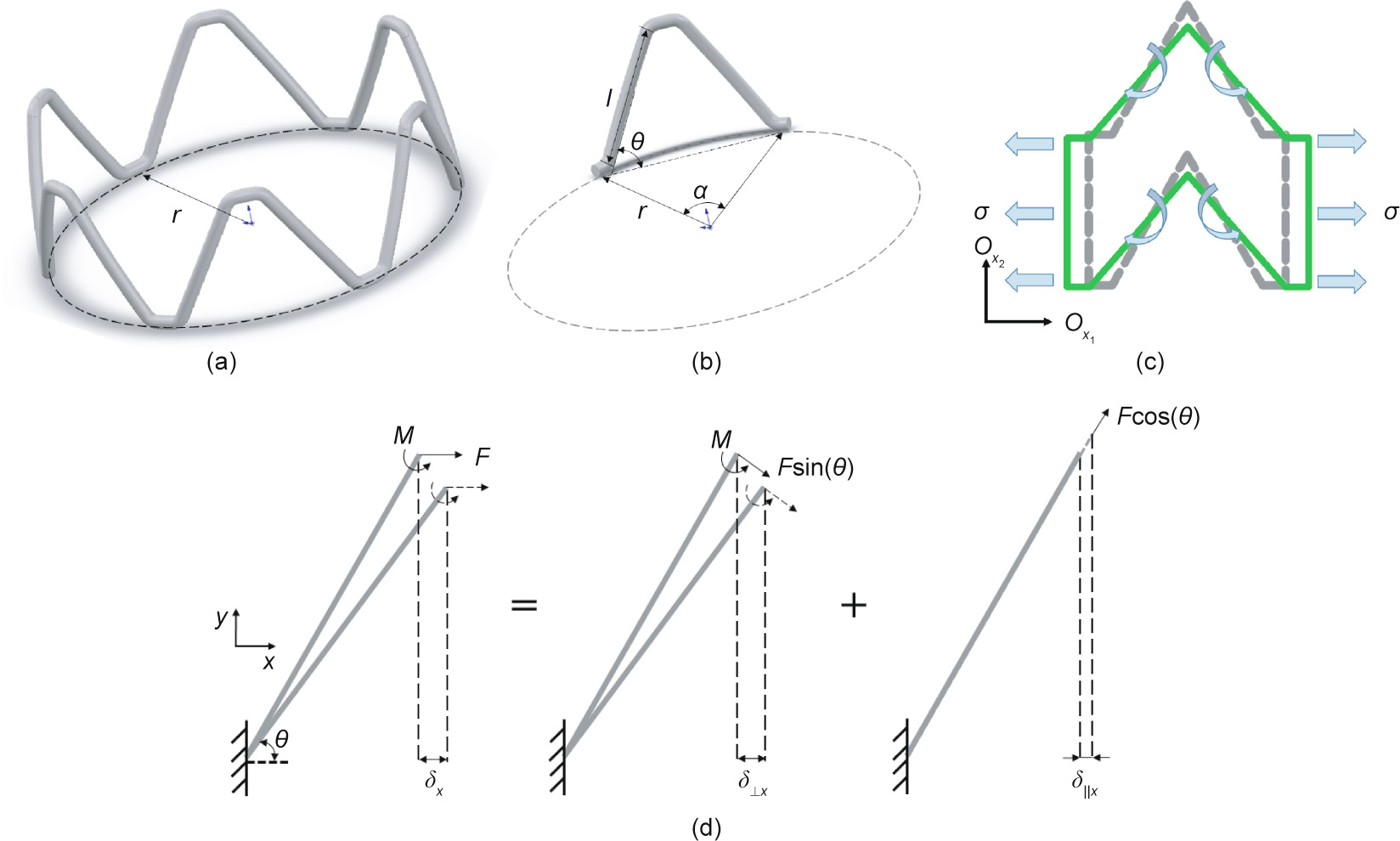
Fig. 2. Schematic diagram of deformation of Z-shaped ring and an inclined rib. (a) A Z-shaped ring; (b) an inclined rib; (c) deformation of a structural unit cell under loading in 2D model; (d) deformation of an inclined rib considering moments and axial force.
The force F can be written in terms of the applied stress as F = . Using the standard definition of the Young’s modulus, and substituting for I, the equivalent elastic modulus of the rib in the x direction is

Here, we substitute , t, h, and as 1.5 mm, 0.2 mm, 1.5 mm, and 60°, and find that
From Eqs. (1)–(13), we can infer that during the stent expansion process, only deformation of the stent structure (the ribs) occurs, and the stent material itself will not deform. Thus, the Poisson’s ratio of structure in Fig. 1(c) for loading in the radial direction can be written as follows:

Because  = 0, it is obvious that
  = 0.
= 0.
Thus, in this application, the direction of the loading force is parallel to the circumferential direction ( ) in the twodimensional (2D) expanded drawing of the stent (Figs. 1(b) and 2(c)) when the stent is dilated. Introducing the ZPR structure (
 = 0) into stent geometry provides an ideal situation in that the length of the stent does not change in the expansion process.
《3. A 3D printing system based on micro-extrusion technology》
3. A 3D printing system based on micro-extrusion technology
《3.1. System configuration》
3.1. System configuration
Many of the polymers that are widely used in medical devices, such as poly(L-lactide) acid (PLLA) and PCL, are thermoplastic materials. FDM as a kind of extrusion-based 3D printing technology that has been widely applied in processing polymer materials. Conventional FDM equipment is based on filament extrusion and the three-axis printing technology, so it requires raw materials to be formed into filaments before being printed. Furthermore, frequent failures of filament buckling during the filament extrusion process result in interruption of the extrusion and necessitate numerous operator interventions [21,22]. In contrast, screw extrusion equipment offers better flexibility in the choice of raw materials. Wang et al. [23] developed a precision extruding deposition (PED) system consisting of a screw-extruder to fabricate PCL tissue scaffolds; the presented PED system directly extrudes materials in its granulated or pellet form without the filament preparation, and deposits freeform. This configuration opens up the opportunity for the use of a wider range of materials. Nonetheless, when the hollow structure and complicated pattern of a stent are taken into consideration, this kind of layer-by-layer deposition method has some limitations, as it is inevitably necessary to print numerous support structures. In addition, it is worth mentioning that the molecular weight of the polymer material decreases with increasing residence time of the melt inside the extruder, so a short and miniature-sized extruder is desirable in the process of biopolymer extrusion [24].
To alleviate these problems, we proposed a screw extrusionbased 3D printing system with the addition of a rotation axis (the fourth axis) and designed a mini-screw extruder. The complete process of stent fabrication is presented in Fig. 3(a). The screw extrusion-based 3D printing system consists of three main components: an x–y–z motion system; a rotation axis (rotating mandrel); and a mini-screw extruder (Fig. 3(b)). The x–y–z motion system adopts a gantry structure, and Panasonic AC servo motors (Japan) are applied for the x-, y-, and z-axes. The shape and length of the rotating mandrel are flexible and can be changed accordingly. To ensure deposition accuracy, the movement of the x–y–z motion system, the rotational velocity of the mandrel, and the rotational velocity of the miniextruder are synchronized based on a programmable multiple axis controller (PMAC) provided by OMRON’s Delta Tau Data Systems (USA).
To ensure the processing quality, the mini-extruder should be taken into consideration as a crucial component in the fabrication system. The structure and main components of the mini-extruder designed in this study are shown in Fig. 3(c). The heating element is attached to the outer surface of the barrel to provide heat for the material. Thus, when the mini-extruder operates, materials in the form of pellets or powder can be added into the extruder through the material inlet and will then be transported downward by the motor-driven screw. The chamber between the screw and the barrel is filled with molten material. Finally, the pressure generated in the chamber helps the molten material to be extruded through the nozzle tip as filaments.
《Fig. 3》
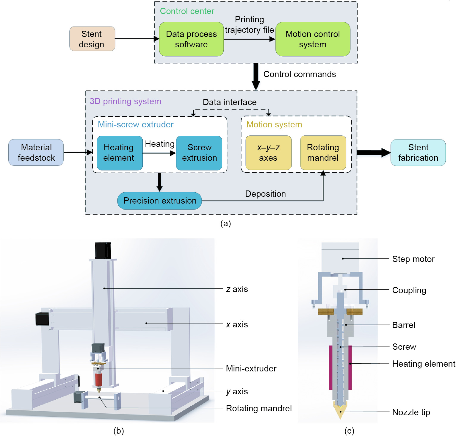
Fig. 3. The custom-made screw extrusion-based 3D printing system. (a) Configuration of stent fabrication system; (b) schematic diagram of 3D printing system; (c) structure and main components of the new-designed mini-extruder.
《3.2. Research on printing parameters》
3.2. Research on printing parameters
To determine a suitable temperature to fabricate 3D-printed stents, extrusion of PCL (material safety data sheet (MSDS) 440744, Sigma-Aldrich, USA) monofilament was first conducted using the home-made mini-extruder in order to observe the forming quality of the extruded filaments. Considering that the width of the stent strut is 100–400 μm, the diameter of the nozzle tip outlet (Φnozzle) was set as 250 μm. Differential scanning calorimetry (DSC) of the raw PCL material was performed using a DSC Q2000 instrument (TA Instruments, Italy) in the temperature range of –80–200 °C, at a heating rate of 10 °C·min–1 , and under a nitrogen flow. Uniaxial tensile tests of the PCL monofilament samples were carried out with a WDW 3020 universal testing machine (Changchun Kexin Test Instrument, China), with a load cell of 50 N and a crosshead displacement of 1 mm·min–1 at room temperature.
The DSC experiment with the raw PCL material shows that PCL has a low melting temperature (Tm) of about 60 °C and a wide range of processing temperatures (Fig. 4(a)). Generally, for the material to melt sufficiently, the heating temperature of the extruder (Textruder) should be set above the melting point (Tm) of the material. As shown in Fig. 4(b), PCL monofilaments were fabricated at five different temperatures between 75 and 85 °C (75, 77.5, 80, 82.5, and 85 °C), with the extruder’s rotation speed set at 11.2 r·min–1 . The samples produced by these temperatures were termed T75, T77.5, T80, T82.5, and T85, respectively. As shown in Fig. 4(c), the filament diameters (Φfilament) of samples T75, T77.5, T80, T82.5, and T85 were determined to be (319.33 ± 5.65), (318.03 ± 6.69), (311.14 ± 2.21), (312.18 ± 3.19), and (315.10 ± 9.48) μm, respectively. The tensile strength of samples T75, T77.5, T80, T82.5, and T85 was determined to be (16.97 ± 0.80), (15.53 ± 1.73), (16.22 ± 0.56), (15.04 ± 0.96), and (14.87 ± 1.55) MPa, respectively.
《Fig. 4》
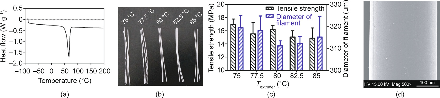
Fig. 4. Investigation of the influence of heating temperature on the extrusion of PCL monofilament. (a) DSC curve of PCL; (b) PCL monofilaments fabricated at five different temperatures between 75 and 85 °C; (c) the effect of temperature on the tensile strength and diameter of monofilaments; (d) scanning electron microscope (SEM) image of PCL filament extruded at 80 °C (SEM, FEI Quanta 200, the Netherlands). Error bars in (c) represent means ± standard deviations. HV: high voltage; Mag: magnitude.
Subsequently, in order to determine the movement velocity of the x–y–z motion system, the rotational velocity of the mandrel (nm, unit: r·min–1 ), and the extruder’s rotation speed (n, unit: r·min–1 ), preliminary printing was conducted with coordination between the motion system, rotating mandrel and mini-screw extruder. As shown in Figs. 3 and 4, only the rotation of the mandrel and the movement of the x-axis (along the axial direction of the mandrel) were required during the fabrication of the stents in this study. Thus, it was possible to simplify the motion process into a 2D motion of VR and Vx, in which VR (unit: mm·s–1 ; nm = VR × 60/(πΦ), where Φ represents the inner diameter of the stent) is the linear velocity of the rotating mandrel and Vx is the movement velocity of x-axis. According to the stent geometry shown in Fig. 1 (θ = 60°), Vx is  times VR. If we define the combined movement velocity of the mandrel and x-axis as VRx , then
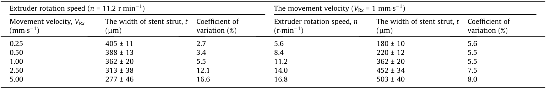
  (unit: mm·s–1 ). In this study, the width of the stent strut (t) can be influenced by changing VRx and the extruder rotation speed (n). As shown in Table 1, as the extruder rotation speed (n) was 11.2 r·min–1 , preliminary printing of the stents was performed at different movement velocities (VRx = 0.25, 0.50, 1.00, 2.50, and 5.00 mm·s–1 ). The width of the stent strut (t) of the samples based on these parameters was determined to be (405 ± 11), (388 ± 13), (362 ± 20), (313 ± 38), and (277 ± 46) μm, respectively. As the movement velocity (VRx) was 1 mm·s–1 , the stents were fabricated at different extruder rotation speeds (n = 5.6, 8.4, 11.2, 14.0, and 16.8 r·min–1 ). The width of the stent strut (t) of the samples based on these parameters were determined to be (180 ± 10), (220 ± 12), (362 ± 20), (452 ± 34), and (503 ± 40) μm, respectively.
《Table 1》
Table 1 The width of the stent strut based on different movement velocity and extruder rotation speed.
《4. Results》
4. Results
《4.1. Stent fabrication》
4.1. Stent fabrication
As reported by Liu et al. [25], in the hot melt extrusion process, when the extruder motor is closed at the end of a line, the screw stops rotating immediately. However, material continues to be extruded from the nozzle tip because the pressure generated inside the extruder is not released. This phenomenon is called ‘‘leakage of materials” and has an adverse effect on fabrication structure. Taking the design of the stent into consideration, the planning of the printing trajectory is crucial in the process of stent fabrication. If repeated starting and stopping of the extruder can be avoided— which also means that there is no need to suddenly move the extruder from one point to another during the printing process— then leakage of materials can be effectively eliminated.
Accordingly, based on the design of the stent, auxiliary lines (gray lines in Fig. 5(a)) were introduced into the printing strategy. The 2D expanded drawings of the printing trajectory are shown in Fig. 5(a), where the direction of the arrows represents the moving direction of the extruder in the printing process. In this printing strategy, the molten filaments are deposited into a series of Zshaped lines (red lines) along the circumferential direction in the first layer. Adjacent Z-shaped lines (red lines) are connected with a ‘‘bridge” line (short black lines) at the end points. In the second layer, parallel straight lines (long black lines), which have a length of H, are printed along the axial direction, and adjacent straight lines (long black lines) are connected with auxiliary lines (gray lines). The materials fuse together at the overlap points of the Zshaped lines (red lines) and straight lines (long black lines). According to the forming method of intersection points, this printing method is called the ‘‘overlapping printing method” in this study.
The designed screw extrusion-based 3D printing system with a mini-extruder was then employed to fabricate stents. The molten material filament was extruded from the nozzle and deposited onto the mandrel. With the synchronized movement of the x–y–z-axes and the rotation of the mandrel, the circumferential and axial filaments were collected successively to complete the fabrication of a stent. Stents were fabricated in a customized manner by changing the diameter and shape of the mandrel and the geometric structure of the stent model. A schematic of the stent fabrication process is shown in Fig. 5(b). The fabrication temperature was set at 80 °C. PLLA (RESOMER L210S, Evonik, Germany) stents and PCL (MSDS 440744, Sigma-Aldrich, USA) stents with different geometric structure were also fabricated (Figs. 5(c)–(e)).
《Fig. 5》
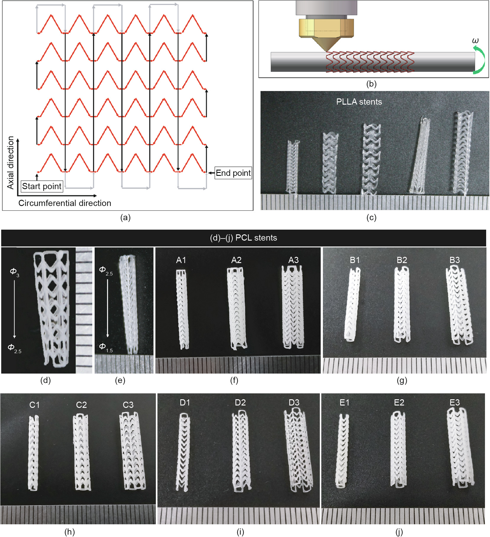
Fig. 5. Fabrication of 3D-printed bioresorbable cardiovascular stents. (a) Printing trajectory of stents; (b) schematic of the stent fabrication process; (c) PLLA stents with different geometry structure; (d, e) tapered PCL stents; (f)–(j) images of stents listed in Table 2 (A1–E3). Φ: the diameter of stents (unit: mm); ω: the angular velocity.
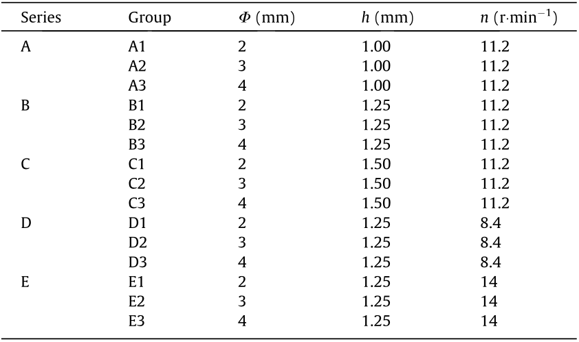
To determine the influence of the stent diameter (Φ), the length of the connector unit (h), and the extruder rotation speed (n) on the mechanical properties of the 3D-printed stents, five series (A–E) of 3D-printed PCL stents were fabricated (Figs. 5(f)–(j)). The experimental groups and parameters are shown in Table 2. For different groups of stents, , θ, and H were constant. In this study, we set = 1.5 mm,  = π/4 0.75, θ = 60°, and H = 15 mm. Thus, according to
 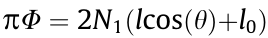 and H = N2h (Fig. 1), when Φ = 2, 3, and 4 mm, N1 is 4, 6, and 8, respectively, and when h = 1.00, 1.25, and 1.50 mm, N2 is 15, 12, and 10, respectively.
《Table 2》
Table 2 Experimental groups and parameters of 3D-printed PCL stents.
《4.2. Morphological analysis》
4.2. Morphological analysis
The surface morphology of the stents was observed by scanning electron microscopy (SEM, FEI Quanta 200, the Netherlands) at an accelerating voltage of 15 kV. Before SEM analysis, the samples were sputter-coated with gold for 60 s. As shown in Fig. 6(a), the stents developed with the ‘‘overlapping printing method” generally showed good surface quality. The intersection points of the stents fabricated with the ‘‘overlapping printing method” are fused by two filaments. It can be seen from the SEM image (Fig. 6) that the PCL monofilaments melted and combined together at the intersection points, ensuring that the stent has good continuity and strength at these points.
《Fig. 6》

Fig. 6. SEM images of stent fabricated with ‘‘overlapping printing method.” (a) Mag 85×; (b, c) Mag 200×.
In addition, a Keyence digital microscope (VHX-500, Japan) was used to observe the surface morphology and measure the width of the stent strut (t). The rotation speed of series D, A–C, and E was 8.4, 11.2, and 14 r·min–1 . As depicted in Fig. 7, the average strut width of series D, A–C, and E was (220 ± 12), (362 ± 42), and (452 ± 35) μm. Specifically, the average width of with the stents in groups A1–A3 and groups B1–B3 was (349 ± 28) and (334 ± 23) μm, and the average width for the stents in groups C1–C3 was (404 ± 38) μm.
《Fig. 7》
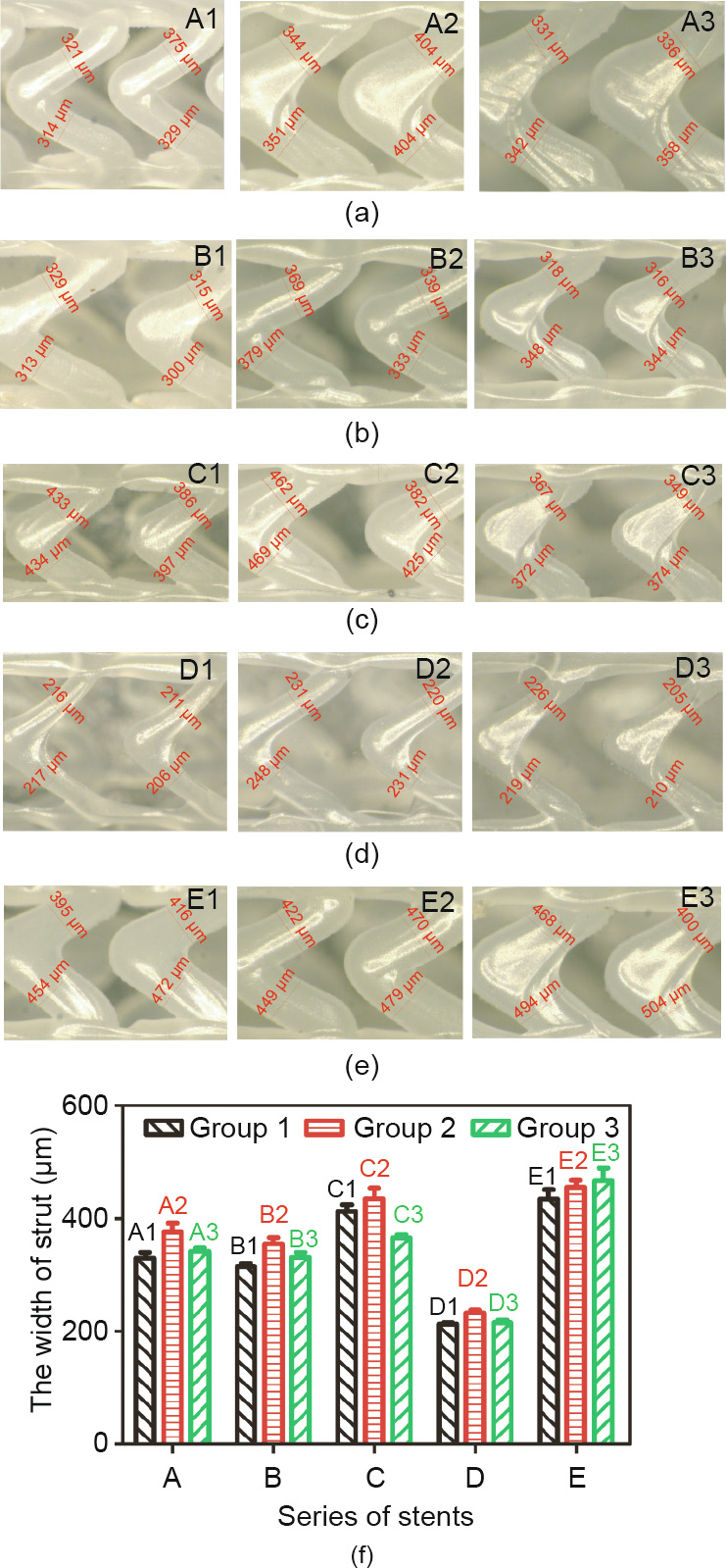
Fig. 7. The width of stent strut of five series (A–E). (a)–(e) Photographs of stents with size marking taken by Keyence VHX-500 microscope; (f) the width of strut of different groups (A1–E3). Error bars in (f) represent means ± standard deviations.
《4.3. Mechanical properties》
4.3. Mechanical properties
A three-point bending test and radial compression test were performed on the 3D-printed PCL stents listed in Table 2 (A1–E3) by installing the corresponding test apparatus (Figs. 8(a) and (b)) on an INSTRON 3365 testing machine (USA) at room temperature according to American Society of Testing Materials (ASTM) F2606-08 and ASTM F3067-14, respectively [26,27]. In addition, a radial expansion test of the groups C1 and C2 stents was performed by means of a dilated balloon (Fig. 8(c)).
《Fig. 8》

Fig. 8. Mechanical properties tests of stents. (a) Three-point bending test; (b) radial compression test; (c) radial expansion test.
4.3.1. Three-point bending test
The three-point bending test is a common means of investigating stent’s bending flexibility, which affects the conformability of the stent (Fig. 9). A stent with good bending flexibility can easily be delivered through the curvature of the artery. Bending flexibility can be represented by bending stiffness: The higher the bending stiffness, the lower the flexibility. According to its definition, bending stiffness can be calculated by E ·I, where E and I are elastic modulus and area moment of inertia. E ·I is given by the following equation [26,28]:

where F, L, and  are the bending force, bending span length, and deflection, respectively. In this test, L is set as 11 mm; thus, when the deflection is set at a certain value, stents with less bending load (F) have better bending flexibility. When the deflection is 2 mm, the loading force of the stents of groups A, B, and C is shown in Fig. 9(d); the force of groups B, D, and E is shown in Fig. 9(h).
In Figs. 9(a)–(d), the bending flexibility of different groups is B1 < A1 ≈ C1, A2 < B2 < C2, and A3 < B3 < C3. As the length of the connector increases from 1 to 1.5 mm, for the Φ2, Φ3, and Φ4 stents, the ratio of the loading force between groups C1/A1, C2/ A2, and C3/A3 is 1.01, 0.77, and 0.49, respectively. As shown in Figs. 9(e)–(h), the bending flexibility of different groups is E1 < B1 < D1, E2 < B2 < D2, and E3 < B3 < D3.
《Fig. 9》
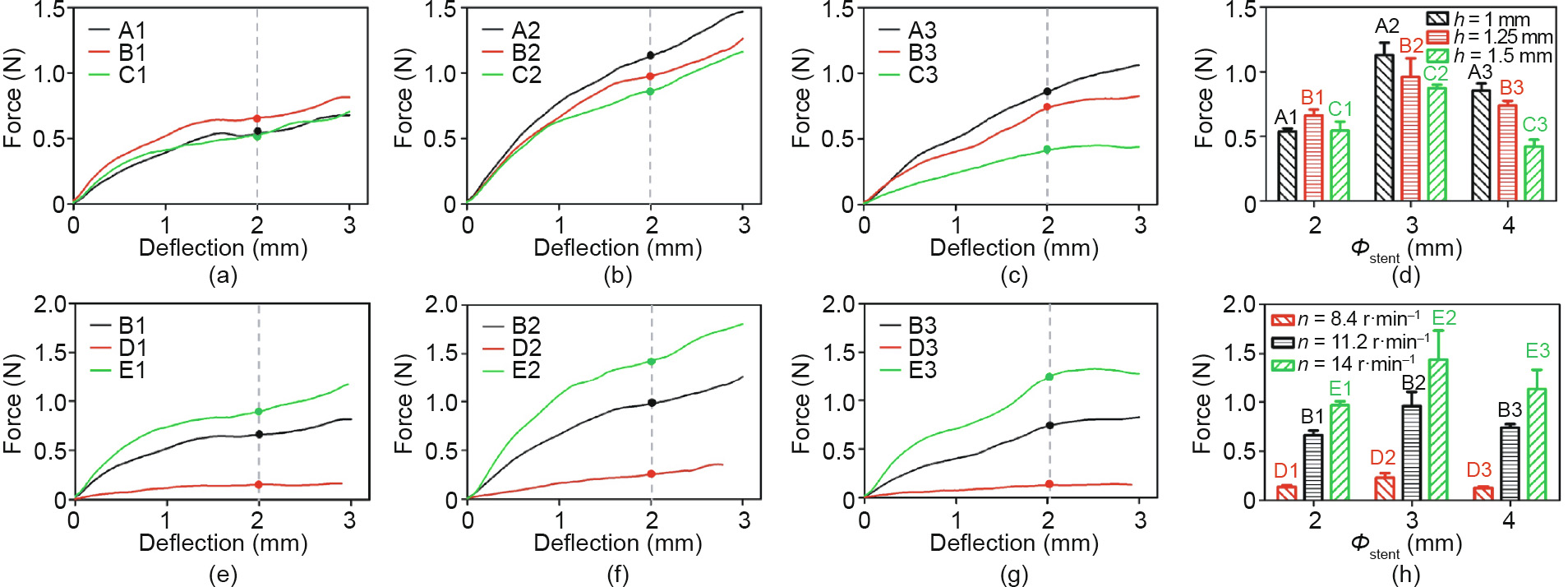
Fig. 9. Force-versus-deflection curves for 3D-printed PCL stents with different geometric unit parameter and fabrication parameter: for (a), (b), and (c), the length of connector (h) is 1, 1.25, and 1.5 mm, respectively; (d) the loading force in (a), (b), and (c) of stents with different diameter and length of connector (h) when the deflection is 2 mm; for (e), (f), and (g), the extruder’s rotation speed (n) is 8.4, 11.2 and 14 r·min–1 , respectively; (h) the loading force in (e), (f), and (g) of stents with different diameters and fabrication parameters (n) when the deflection is 2 mm. Error bars in (d) and (h) represent means ± standard deviations.
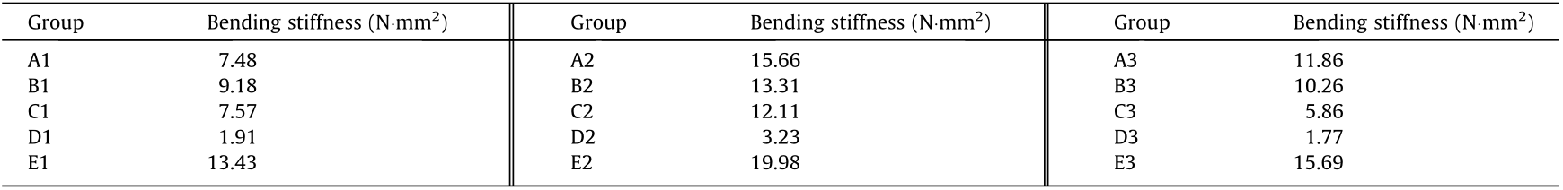
The bending stiffness values (average value) of the stents at a deflection of 2 mm are given in Table 3. In contrast, the A1, C1, C3, and D1–D3 stents have relatively better bending flexibility. In a previous publication [29], the expanded Abbott Absorb GT1 stents (diameter: 3.0 mm, length: 18 mm) were shown to have a bending stiffness value of 4.20 N·mm2 , which is close to the bending stiffness values of the A1, C1, C3 and D1–D3 stents. This indicates that within these 15 groups of stents, the A1, C1, C3, and D1–D3 stents have applicable bending flexibility.
《Table 3》
Table 3 Bending stiffness values of 3D-printed stents.
4.3.2. Radial compression test
The Radial compression test was applied to evaluate the radial strength, which determines the radial support force of the stent. Stents with good radial strength can provide better support. Radial strength can be represented by radial stiffness: The higher the radial stiffness, the lower the radial strength. Schmidt et al. [30] suggested that radial stiffness is determined from the profile decreasing in a physiologically relevant range from 0 to 0.2 bar (1 bar = 105 Pa) outer pressure (Eq. (16)). ASTM F3067-14 [27] suggests that when using an area normalized force, the instantaneous stent diameter should be used (instead of the starting diameter), multiplied by the initial length (Eqs. (17)–(18)). Accordingly, the radial stiffness is the compression ratio when the instantaneous pressure acting on the stents is 0.2 bar.

Theinstantaneouspressure

A stent’s radial strength is mainly related to the width (t) and number of Z-shaped rings. In Figs. 10(a)–(d), it can be seen that the radial stiffness of the different groups is Bi > Ci > Ai (i = 1, 2, 3); thus, the radial strength of the different groups is Bi < Ci < Ai (i = 1, 2, 3). From Figs. 10(e)–(h), it is obvious that the radial stiffness of the different groups is Di > Bi > Ei (i = 1, 2, 3); thus, the radial strength of the different groups is Di < Bi < Ei (i = 1, 2, 3).
In a previous publication [30], the radial stiffness varied from 0.51% to 3.99%, which is close to the radial stiffness values of the A2, A3, C2, C3, and E3 stents. This indicates that within these 15 groups of stents, the A2, A3, C2, C3, and E3 stents have applicable bending flexibility.
《Fig. 10》
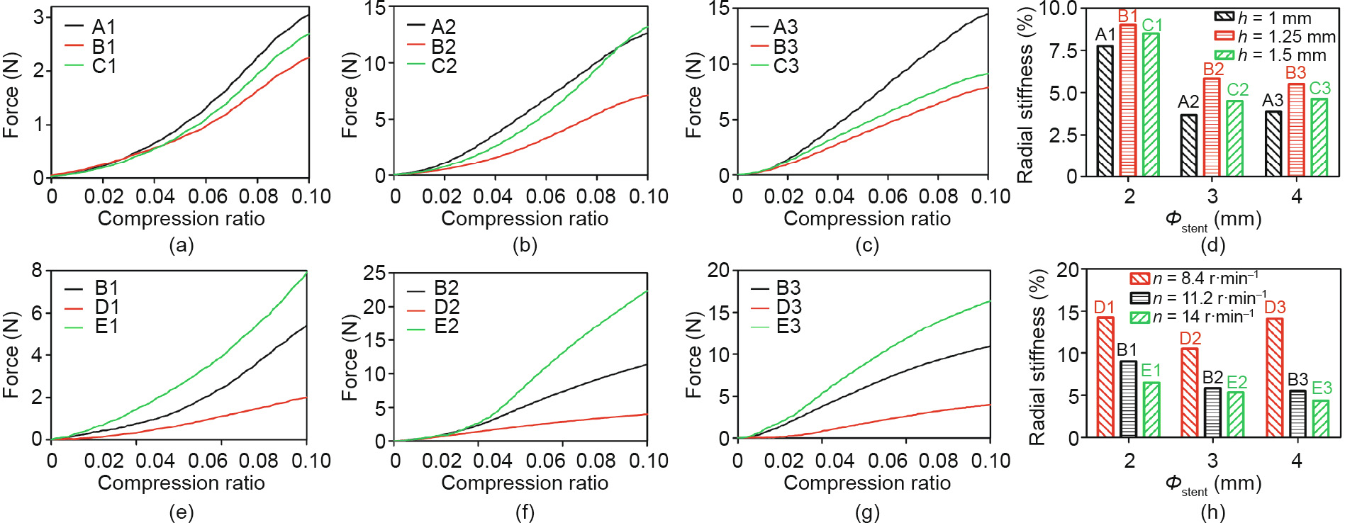
Fig. 10. Force-versus-compression ratio curves for PCL stents with different geometric unit parameter and rotation speed (n). For stents in (a), (b), and (c), the length of connector (h) is 1, 1.25, and 1.5 mm, respectively; (d) the radial stiffness of stents in (a), (b), and (c); for stents in (e), (f), and (g), rotation speed (n) is 8.4, 11.2, and 14 r·min–1 , respectively; (h) the radial stiffness of stents in (e), (f), and (g). Error bars in (d) and (h) represent means ± standard deviations.
4.3.3. Radial expansion test
Samples (the C1 and C2 stents) were expanded from the original mode until the expansion ratio became 10% and 20%, respectively. Group C1 stents with a diameter of 2 mm were expanded into about 2.2 and 2.4 mm, respectively. Group C2 stents with a diameter of 3 mm were expanded into about 3.3 and 3.6 mm, respectively. After that, the radial forces were removed and the stents recoiled in the radial direction. The diameter of each sample in the original mode (OΦ), expansion maximum mode (MΦ) and recoil mode (RΦ) is shown in Fig. 11(a). The radial recoil ratio after removing the radial force can be calculated by the following:

The average radial recoil ratio of the C1 stents expanded to 110% and 120% was 69% and 41%, respectively, while that of the C2 stents was 77% and 71%. The extent of the radial recoil of the 3D-printed PCL stents was unsatisfactory, which is related to the excellent elongation rate of PCL material. To resolve this problem, other biomaterials will be explored in future studies.
The length of each sample in the original mode (OL), expansion maximum mode (ML), and recoil mode (RL) is shown in Fig. 11(b). The longitudinal foreshortening ratio when the stents were expanded into the maximum mode can be calculated by the following:
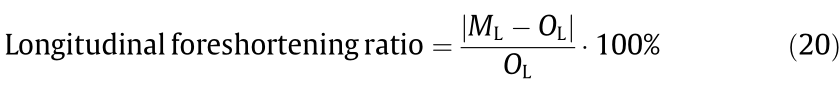
The longitudinal foreshortening ratio of the C1 stents expanded to 110% and 120% was 0.33% and 0.13%, respectively, while that of the C2 stents was 0.40% and 0.09%. In contrast, current commercial stents have a shortening rate of 3%–5% [31]. Thus, it can be verified that the stent geometry designed in this study can achieve a substantially steady axial length after being expanded.
《Fig. 11》
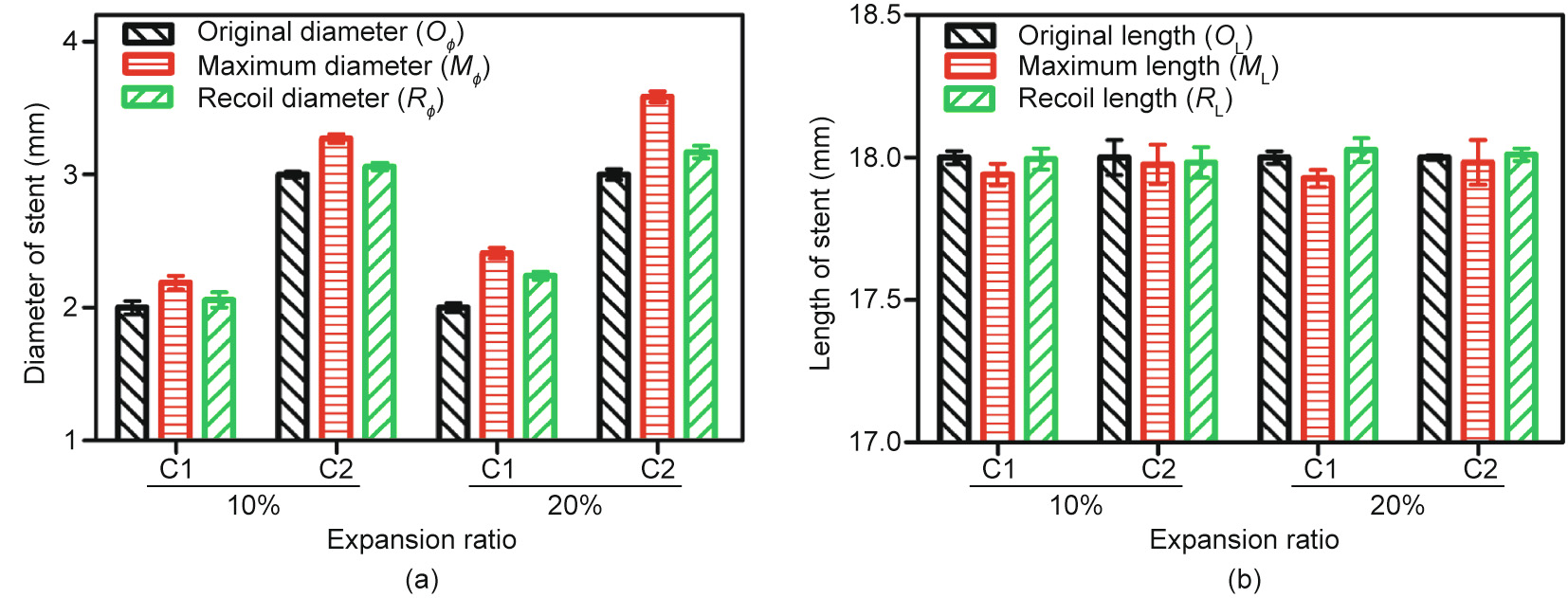
Fig. 11. Radial expansion results: (a) the change of stent diameter; and (b) the change of stent length. Error bars represent means ± standard deviations.
《4.4. Biocompatibility》
4.4. Biocompatibility
Hemolysis analysis of the 3D-printed stents was conducted in accordance with ASTM F756-17 [32]. Fresh human blood obtained from voluntary donors was legally supplied by Beijing Huaxin Hospital, the First Affiliated Hospital of Tsinghua University. The hemolysis rate was determined by measuring hemoglobin release under static conditions, as previously reported [33]. The hemolysis rate was calculated according to Eq. (21):

where ODt represents the optical density of the test group, and ODp and ODn represent the absorbance of the positive and negative groups, respectively. According to ASTM F756-17 [32], the hemolysis of materials is classified as non-hemolytic (0–2%), slightly hemolytic (2%–5%), or hemolytic (> 5%). The hemolysis rate of the 3Dprinted PCL was 0.07% ± 0.02%, which is non-hemolytic.
A cytocompatibility evaluation of the 3D-printed stents was performed according to ISO 10993–5:2009 [34]. Human umbilical vein endothelial cells (HUVECs; ATCC, USA) were cultured in clonetics endothelial cell growth medium-2 (EGM-2; cc3162, Lonza, Switzerland). Extracts of 3D-printed PCL were prepared by immersing samples in EGM-2 at 37 °C for 24 h. Cell viability was detected by adding 10 μL of cell counting kit-8 (CCK-8) (Dojindo Laboratories, Japan) in each well after the HUVECs were cultured in extracts for 96 h; next, then the optical density (OD) value for each well was read at a wavelength of 450 nm in order to determine the cell viability on a microplate reader (Multiskan, Thermo, USA). The cell viability was calculated according to Eq. (22):

where ODt represents the OD value of the test group, and ODp and ODn represent the OD values of the positive and negative groups, respectively. According to the cell viability value, the cytotoxicity reactivity of the materials was classified as Grade 0 (≥ 100%), Grade 1 (80%–99%), Grade 2 (50%–79%), Grade 3 (30%–49%), or Grade 4 (0– 29%). When the grade is more than 2, a material is considered to have cytotoxic effects. The cell viability of the 3D-printed PCL was 90% ± 5%, which is Grade 1.
The results of the hemolysis rate and cell viability confirmed the potential application of 3D-printed stents in vascular implantation.
《5. Discussion》
5. Discussion
《5.1. Effect of printing parameters on printing-ability and structural formability》
5.1. Effect of printing parameters on printing-ability and structural formability
5.1.1. Heating temperature of the extruder
Before stent fabrication, extrusion of PCL monofilaments was conducted to investigate the effect of the heating temperature of the extruder (Textruder) on the strength and dimensional stability of the extruded monofilament. By comparing the accuracy of the filament diameter of different groups, it was found that the PCL filaments had better dimensional stability when Textruder was 80 and 82.5 °C (Fig. 4(c)), while samples extruded at 75 and 80 °C had the advantage in terms of tensile strength. Consequently, considering both strength and dimensional stability, the heating temperature of the extruder was set at 80 °C. This temperature was used in the subsequent stent fabrication process. As shown in Figs. 4(b) and (d), the PCL filament extruded at 80 °C showed good surface morphology.
5.1.2. Movement velocity of the x-axis system, rotational velocity of the mandrel, and extruder rotation speed
Table 1 shows that the width of the stent strut (t) can be changed by adjusting the movement velocity (VRx) and extruder rotation speed (n). As VRx increases, the width of the stent strut becomes smaller and the printing stability decreases (the coefficient of variation increases). When extruder rotation speed (n) increases, the width of the stent strut increases and shows better precision (the coefficient of variation is lower). Therefore, for a comprehensive consideration of printing stability (e.g., for a coefficient of variation less than 10%) and printing efficiency, the movement velocity (VRx) was set at 1 mm·s–1 and the width of the strut was controlled by changing the extruder rotation speed (n). Accordingly, the movement velocity of the x-axis (Vx) is  mm·s–1 (0.866 mm·s–1) and the linear velocity of the rotating mandrel (VR) was 0.5 mm·s–1 . Thus, the rotational velocity of the mandrel (nm, unit: r·min–1 ) was 30/(πΦ) r·min–1 (where Φ represents the inner diameter of the stent). Extruder rotation speed (n) of 8.4, 11.2, and 14 r·min–1 were then adopted in the subsequent experiments
5.1.3. Filament extrusion speed
The filament extrusion speed depends on the rotation speed of the extruder. The higher the rotation speed is, the faster the filaments are extruded. The rotation speed of series D, A–C, and E was 8.4, 11.2, and 14 r·min–1 , respectively. As depicted in Fig. 7, the stents of series A, B, and C show a middle value in the width of strut (t), while series D has a relatively lower t and series E has a greater t. It is clear that the width of the stent strut is positively related to the rotation speed of the extruder: The greater the rotation speed, the larger the width of the strut. The stents in the series A, B, and C were fabricated with the same rotation speed. However, compared with the stents in series A and B, the stents in series C had a relative larger dimension of the stent strut. Therefore, the stability of stent fabrication needs to be improved in the future studies.
《5.2. Effect of structural parameters on the mechanical properties of 3D-printed stents》
5.2. Effect of structural parameters on the mechanical properties of 3D-printed stents
In the literature, various methods have been used to examine a stent’s mechanical properties. The bending flexibility property and radial strength are two important indicators of the mechanical properties of a stent, which are closely related to the geometric parameters of the stent [14,28]. Based on the discussion in Sections 4.3.1 and 4.3.2, it is noted that bending flexibility can be represented by bending stiffness, with a higher bending stiffness resulting in a lower flexibility. Radial strength can be represented by radial stiffness, with a higher radial stiffness resulting in a lower radial strength. In this study, the main parameters affecting the mechanical properties of stents were the length of the connector and the width of the stent strut.
5.2.1. Length of connector (h)
The difference between series A, B, and C is the length of the connector (h), which is 1, 1.25, and 1.5 mm, respectively. Because the length of the stent is constant, it is clear that the longer the connector h is, the fewer the number of Z-shaped rings will be, resulting in greater bending flexibility and lower radial strength. Thus, the theoretical result for bending flexibility and radial strength should be Ai < Bi < Ci and Ci < Bi < Ai (i = 1, 2, 3), respectively.
In regard to bending flexibility, Figs. 9(a)–(d) and Table 3 show that the bending flexibility of the different groups is B1 < A1 ≈ C1, A2 < B2 < C2, and A3 < B3 < C3. On the whole, stents gain an advantage in bending flexibility as the length of the connector increases. This trend is particularly pronounced for stents with relatively larger diameter. In regard to radial strength, Figs. 10(a)–(d) show that the radial stiffness of different groups is Bi > Ci > Ai (i = 1, 2, 3); thus, the radial strength of different groups is Bi < Ci < Ai (i = 1, 2, 3), which is different from the theoretical result. This finding will be explained in Section 5.2.2.
In conclusion, stents with a longer connector have an advantage in terms of bending flexibility. However, it is not conclusive in this part whether a longer connector is strictly unfavorable for radial strength.
5.2.2. Width of stent strut (t)
The difference between series D, B, and E is the extruder rotation speed (n), which is 8.4, 11.2, and 14 r·min–1 , respectively. Because the width of the stent strut is positively related to the rotation speed of the extruder, the greater the rotation speed is, the larger the width of the strut will be, resulting in lower pending flexibility and greater radial strength. Thus, the theoretical result for bending flexibility and radial strength should be Ei < Bi < Di and Di < Bi < Ei (i = 1, 2, 3), respectively.
As expected, Figs. 9(e)–(h), Table 2, and Figs. 10(e)–(h) show that the experimental results for bending flexibility and radial strength are consistent with the theoretical situation. These results confirm that the strut width (t) is a dominating factor for the radial strength of stents. Furthermore, as mentioned above, the radial strength of groups A–C is Bi < Ci < Ai (i = 1, 2, 3), which does not match with the theoretical result of Ci < Bi < Ai. This result can be explained in terms of the width of the stent strut (t). From Fig. 7(f), it can be determined that the strut width of the Ci stents is relatively larger than that of the Bi stents (i = 1, 2, 3).
5.2.3. Brief summary
Based on the discussion in Sections 5.2.1 and 5.2.2, it can be seen that bending flexibility and radial strength are a pair of contradictory properties. This is a result of a trade-off of stent structure parameters to realize integrated mechanical properties. For stents of the same diameter, the mechanical properties (bending flexibility and radial strength) of the stents are closely related to the length of the connector and the width of the stent strut. In regard to the bending flexibility of stents with the same diameter, it can be seen that stents with a longer connector and a smaller width of stent strut (t) have advantages; therefore, stents with a loose geometric structure tend to show better flexibility. In regard to the radial strength of stents with the same diameter, it can be inferred that the strut width (t) is a dominating factor. The answer can be obtained from Eq. (12), which indicates that the structural strength of the stent is proportional to t3 and inversely proportional to h; this means that the properties of the stent are more susceptible to the strut width (t). It can be inferred that stents with a larger connector (h) and a moderate strut width are more conducive for a balance between bending flexibility and radial strength.
《6. Conclusions》
6. Conclusions
In this study, a home-made screw extrusion-based 3D printing system using a mini-screw extruder was developed to fabricate stents while adding a fourth rotation axis (the mandrel). A stent with ZPR structure was designed and was demonstrated to be steady in axial length after expansion. Preliminary testing was conducted to investigate appropriate fabrication parameters with monofilament experiments. Subsequently, stents (made of PLLA and PCL) with different shape and geometric structures were fabricated in a customized manner using the ‘‘overlapping printing method.” In addition, the mechanical properties of PCL stents with different parameters were determined.
In conclusion, the screw extrusion-based 3D printing system reported here shows potential for customizable stent fabrication. PCL stents are well studied in terms of morphology and mechanical analysis. However, the insufficiency of stent flexibility indicates a need for more efforts in stent design in future research. Furthermore, in comparison with metal stents, PCL stents are not completely reliable in term of radial strength and radial recoil. PLLA or other biopolymers with greater strength and a lower elongation rate will be explored for stent fabrication.
《Acknowledgements》
Acknowledgements
The authors acknowledge funding support from the Beijing Municipal Natural Science Foundation, China (Z150001). This work was also supported by Beijing Anzhen Hospital.
《Compliance with ethics guidelines》
Compliance with ethics guidelines
Chengjin Wang, Lei Zhang, Yongcong Fang, and Wei Sun declare that they have no conflict of interest or financial conflicts to disclose.


 京公网安备 11010502051620号


